radiator cap Citroen CX 1983 1.G Workshop Manual
[x] Cancel search | Manufacturer: CITROEN, Model Year: 1983, Model line: CX, Model: Citroen CX 1983 1.GPages: 394
Page 10 of 394
Downloaded from www.Manualslib.com manuals search engine 4 OPERATION N” MA. 000 : General characteristics
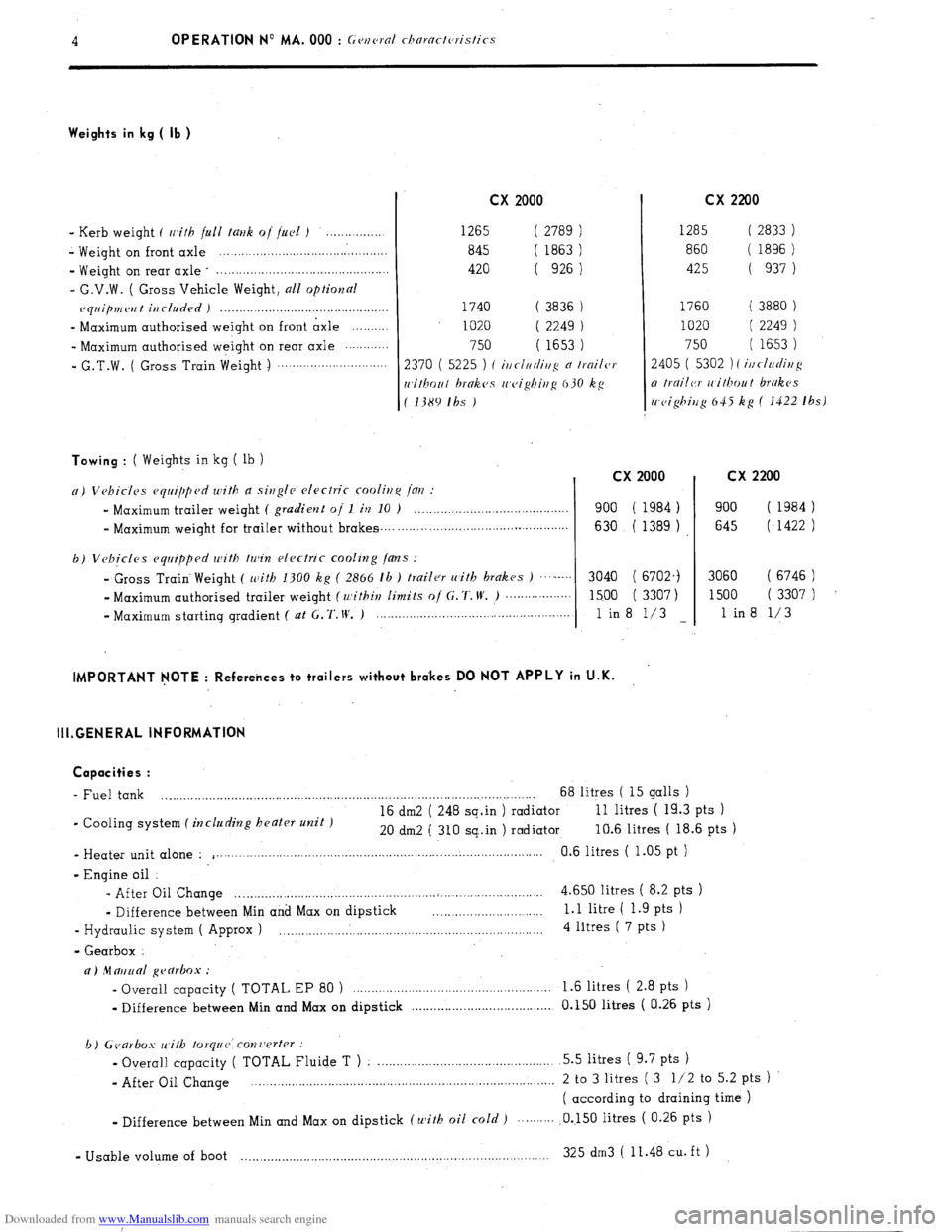
Weights in kg ( lb )
- Kerb weight ( with full tallk oj fuel ) . . . . . . . . . .
- Weight on
front axle ...............................................
- Weight on rear axle ................................................
- G.V.W. ( Gross Vehicle Weight, all optional
ecpiip777ei7t i77cluded )
..............................................
- Maximum authorised weight on front axle ..........
- Maximum authorised weight on rear axle ............
I G.T.W. ( Gross Train
Weight )
..............................
Towing : ( Weights in kg ( lb ) cx 2000
1265 ( 2789
) 1285
( 2833 )
845
( 1863 ) 860
( 1896)
420 ( 926
1 425
( 937 1
1740 ( 3836
) 1760 ( 3880 )
1020 ( 2249 ) 1020 ( 2249 )
750 ( 1653 ) 750 ( 1653)
2370 ( 5225
) I i77cI77rfi77!: n Ir.oiler 2405 ( 5302 )
( i/7t/ur/i77g
rc,i/hou/ brnkes cc,eighiug 630 kg o trc7ilcr rt~ithou t brakes
( 1389 Ihs ) rc~ei$iu~ 645 kg ( 1422 Ibs)
n) Vehicles equipped with a single electric cooli,f,c /c[i7 :
”
Maximum trailer weight ( gradient of 1 h 10 ) .__._..,...__,_____............
- Maximum
weight for bailer without brakes _.., .__._. ,. _._..,.,_..,__.._...... . . . . . . . . . . . .
b)
Vehicles equipped with tu& electric cooling /ans :
-
Gross Train. Weight ( zc:ith 1300 kg ( 2866 lb ) trailer with brakes ) .....-.’
- Maximum authorised trailer weight (within limits o/ C. 7‘. W’. ) ~..~~...~.....~~~
- Maximum starting gradient ( at G. ‘f. IV, )
_______.._....._...,.................................
cx 2200
cx 2000
900 ( 1984 )
630 ( 1389 )
3040 ( 6702.)
1500 ( 3307)
1 in8 l/3
- cx 2200
900 ( 1984)
645 (,I422 )
3060 ( 6746 )
1500 ( 3307 )
1 in8 l/3
IMPORTANT NOTE : Referehces to trailers without brakes DO NOT APPLY in U.K.
III.GENERAL INFORMATION
Capacities :
- Fuel tank
. . .._....__........................................................................................... 68 litres ( 15 galls )
- Cooling system
(including beater unit ) 16 dm2 ( 248 sq.in ) radiator 11 litres ( 19.3 pts )
20 dm2 ( 310 sq..in ) radiator 10.6 litres ( 18.6 pts )
- Heater unit alone :
i . . ..___.___.._.._.._..........................,..,.,..................................... Cl.6 litres ( 1.05 pt )
- Engine oil :
- After Oil Change _......_._.,_....,..,....,.......,....,................~.,.........................,
4.650 litres ( 8.2 pts )
w
Difference between Min and Max on dipstick 1.1 litre ( 1.9 pts )
- Hydraulic system ( Approx ) 4 litres ( 7 pts )
- Gearbox
a) ‘11 mud ~earlmx :
- Overall capacity ( TOTAL EP 80 ) _.__.__._..._..._._................................... 1 .6 litres ( 2.8 pts )
w
Difference between Min and Max on dipstick . . . . . . . . . . . . . . . . . .._................... 0.150 litres ( a.26 pts )
b) Ccarbos with
/orque: con7jerter :
- Overall capacity ( TOTAL Fluide T ) . ..__.,_.____________....,.,....,....,,.......... 5.5 litres ( 9.7 pts )
- After Oil Change . . 2 to 3 litres ( 3 l/2 to 5.2 pts )
( according to draining time )
v
Difference between Min and Max on dipstick (with oil
cold ) .0..150 litres ( 0.26 pts )
- Usable volume of boot
325 dm3 ( 11.48 cu. ft ) . . . . . . . . . . . . . . . . . .._................................................................
Page 14 of 394
Downloaded from www.Manualslib.com manuals search engine 8 OPERATION No MA. 000 : G~v2~~rnl characteristics
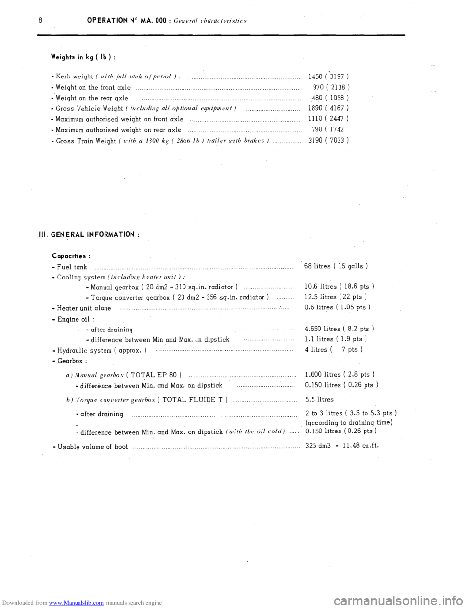
Weights in kg ( Jb ) :
- Kerb weight ( with /hll fmk oipc~trol ) :
.............................................................. 1450 (3197 )
- Weight on the front axle .... .._
.................................................................................... 970 ( 2138 )
- Weight on the rear axle ..................................
.....................................................
480 ( 1058 )
- Gross Vehicle Weight ( inclr~cli22~ all optimaal eq~ipmm f )
.............................. 1890 ( 4167 )
- Maximum authorised weight on front axle
.............................................. . ............. lllO( 2447 )
- Maximum authorised weight on rear axle ............................................................... 790 ( 1742
- Gross Train Weight
( with ~2 1300 kg ( 2866 lb 1 frailer u'ith hmkes I ................ 3190 ( 7033 ) III. GENERAL INFORMATION :
Capacities :
- Fuel tank . . . .._._.............., .._.._._. . .._...__................................ ._................,...... 68 litres ( 15 galls )
- Cooling system (i22cludi22g hcc?ter ul2it 1 :
- Manual gearbox ( 20 dm2 - 310 sq.in. radiator ) . . .._.....................
10.6 litres ( 18.6 pts )
m
Torque converter gearbox ( 23 dm2 - 356 sq.in. radiator ) . 12.5 litres (22 pts )
- Heater unit alone _, :. I.
0.6 litres ( 1.05 pts )
- Engine oil :
- after draining . . .._._._......._._........................................................-..........
4.650 litres ( 8.2 pts )
.. difference between Min and Max. ,.n dipstick 1 .l litres ( 1.9 pts )
- Hydraulic system ( approx. ) .._._..._.__.._._._...,,..,........,.,......................................
4 litres (
7 pts 1
- Gearbox :
a) ~Z~UI/I~U/ gcarho.~ ( TOTAL EP 80 ) _,.,__.___.,.,_._....,,,...................,...........,. 1.600 litres ( 2.8 pts )
- difference between Min. and Max. on dipstick . . . . . . . . . ..__...................
0.150 litres ( 0.26 pts )
h)
Torque corztwrter gcarhox ( TOTAL FLUIDE T ) ._.___._...,,___.._....,...,.....,., 5.5 litres
- after draining
_ 2 to 3 litres ( 3.5 to 5.3 pts )
(qccording to draining time)
- difference between Min. and Max. on dipstick
(with rhc oil cold) . . . . .’ 0.150 litres ( 0.26 ‘pts )
w Usable volume of boot ..___._._.......___................,.............,.............,.......,.,.....,............ 325 dm3 - 11.48 cu.ft.
Page 170 of 394
Downloaded from www.Manualslib.com manuals search engine CHARACTERISTICS
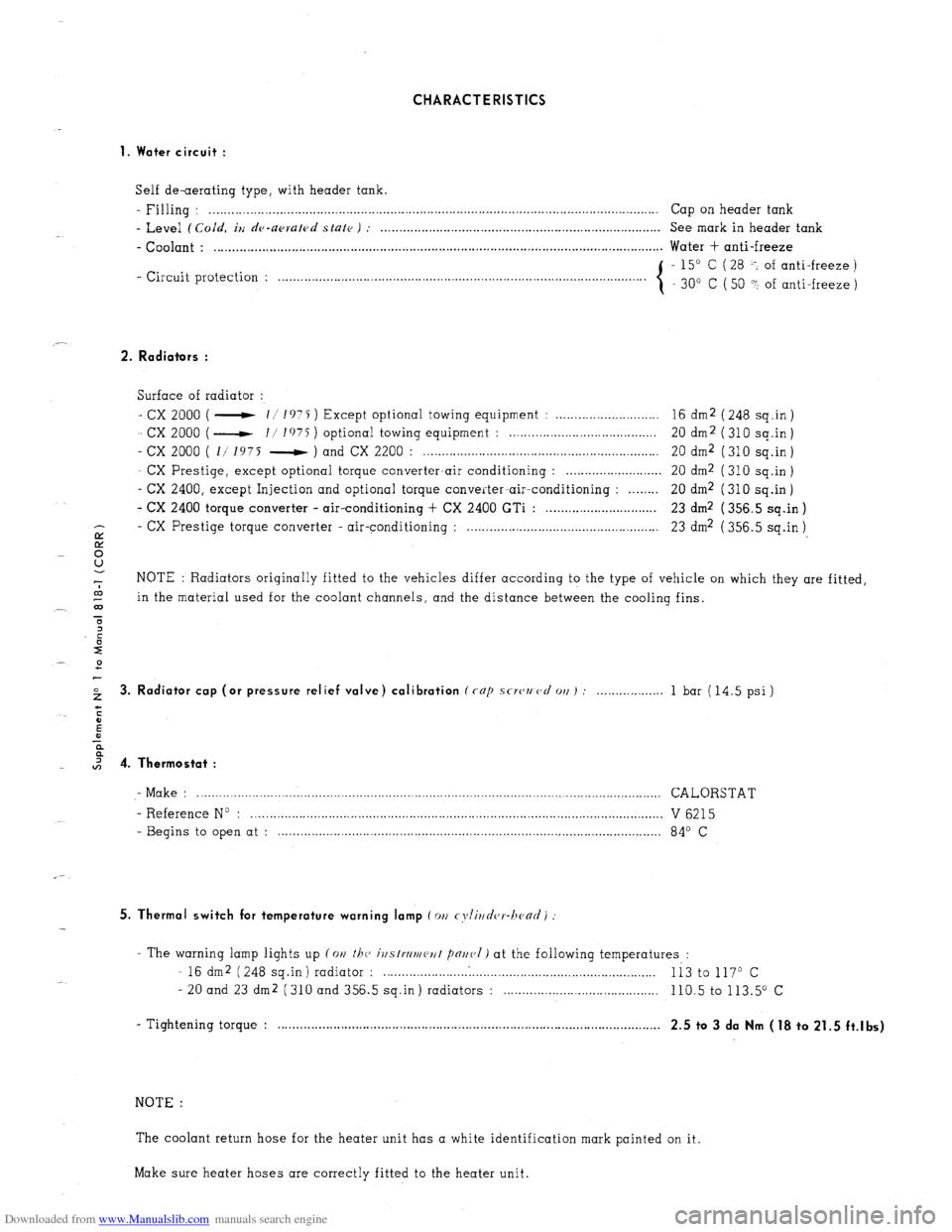
1. Water circuit :
Self de-aerating type, with header tank.
- Filling : . . . . . . . .._................................................................................................................ Cap on header tank
- Level (Cold, iu de-upruled state ) : . . . . . . . . . . . . . . . . . . . . . . . . . . . . . . . . . . . . . . . . . . . . . . . . . . . . . . . . . . . . . . . . . . . . . . . . . . . . See mark in header tank
- Coolant : . . . . . . . . . . . . . . . . . . . . . . . . . . . . . . . . . . . . . . . . . . . . . . . . . . . . . . . . . . . . . . . . . . . . . . . . . . . . . . . . . . . . . . . . . . . . . . . . . . . . . . . . . . . . . . . . . . . . . . . . .. Water + anti-freeze
- Circuit protection : - 15” C ( 28 -: of anti-freeze )
. . . . . . . . . . . . . . . . . . . . .
30” C ( 50 ? of anti-freeze )
2. Radiators :
Surface of radiator :
- cx 2000 ( - 11 1975 ) Except optional towing equipment : . . . . . . . . . . . . . . . . . . . . . . . . . . . . 16 dm2 ( 248 sq.in )
- cx 2000 ( - I/ I’)75 ) optional towing equipment : . . . . . . . . . . . . . . . . . . . . . . . . . . . . . . . . . . . . . . 20 dm2 (310 sq.in)
- cx 2000 ( 1/ 1975 - ) and CX 2200 : . . . . . . . . . . . . . . . . . . . . . . . . . . . . . . . . . . . . . . . . . . . . . . . . . . . . . . . . . . . . . . . . 20 dm2 ( 310 sq.in )
- CX Prestige, except optional torque converter-air conditioning : . . . . . . . . . . . . . . . . . . . . . . . . . . 20 dm2 ( 310 sq.in )
- CX 2400, except Injection and optional torque converter-air-conditioning : . . . . . . . . 20 dm2 (310 sq.in)
- CX 2400 torque converter - air-conditioning + CX 2400 GTi : . . . . . . . . . . . . . . . . . . . . . . . . . . . . . . 23 dm2 ( 356.5 sq.in )
- CX
E Prestige torque converter - air-conditioning : . . . . . . . . . . . . . . . . . . . . . . . . . . . . . . . . . . . . . . . . . . . . . . . . . . . . 23 dm2 ( 356.5 sq.in )
8
-7 NOTE : Radiators originally fitted to the vehicles differ according to the type of vehicle on which they are fitted,
co
_- 03 in the material used for the coolant channels, and the distance between the cooling fins.
T
2 3. Radiator cap (or pressure relief valve) calibration (rap scwzmcl 011) : . . . 1 bar (14.5 psi)
I 4. Thermostat :
- Make : .............................................................................................................................. CALORSTAT
- Reference No : ................................................................................................................ V 6215
- Begins to open at : ........................................................................................................ 84’ C
5. Thermal switch for temperature warning lamp (011 cyli~~d(,r-hc~ad)
- The warning lamp lights up (on the, ivstrrlmeut pnr~(,I) at the following temperatures :
- 16 dm2 (248 sq.in) radiator : . . . . . . . . . . . . .
Ii3 to 117O c
- 20 and 23 dm2 (310 and 356.5 sq.in) radiators : . . . . 110.5 to 113.5” c
- Tightening torque : . . . . . . . . . . . . . . . . . . . . . . . . . . . . . . . . . . . . . . . . . . . . . . . . . . . . . . . . . . . . . . . . . . . . . . . . . . . . . . . . . . . , . . . . . . . . . . . . . . . . . . . .
2.5 to 3 da Nm (18 to 21.5 ft.lbs)
NOTE :
The coolant return hose for the heater unit has a white identification mark painted on it.
Make sure heater hoses are correctly fitted to the heater unit.
Page 178 of 394
Downloaded from www.Manualslib.com manuals search engine OPERATION No MA. 230.0 : M k
08 ,ri,y r,i, //I<’ roo/i,ip c, s,w,,.
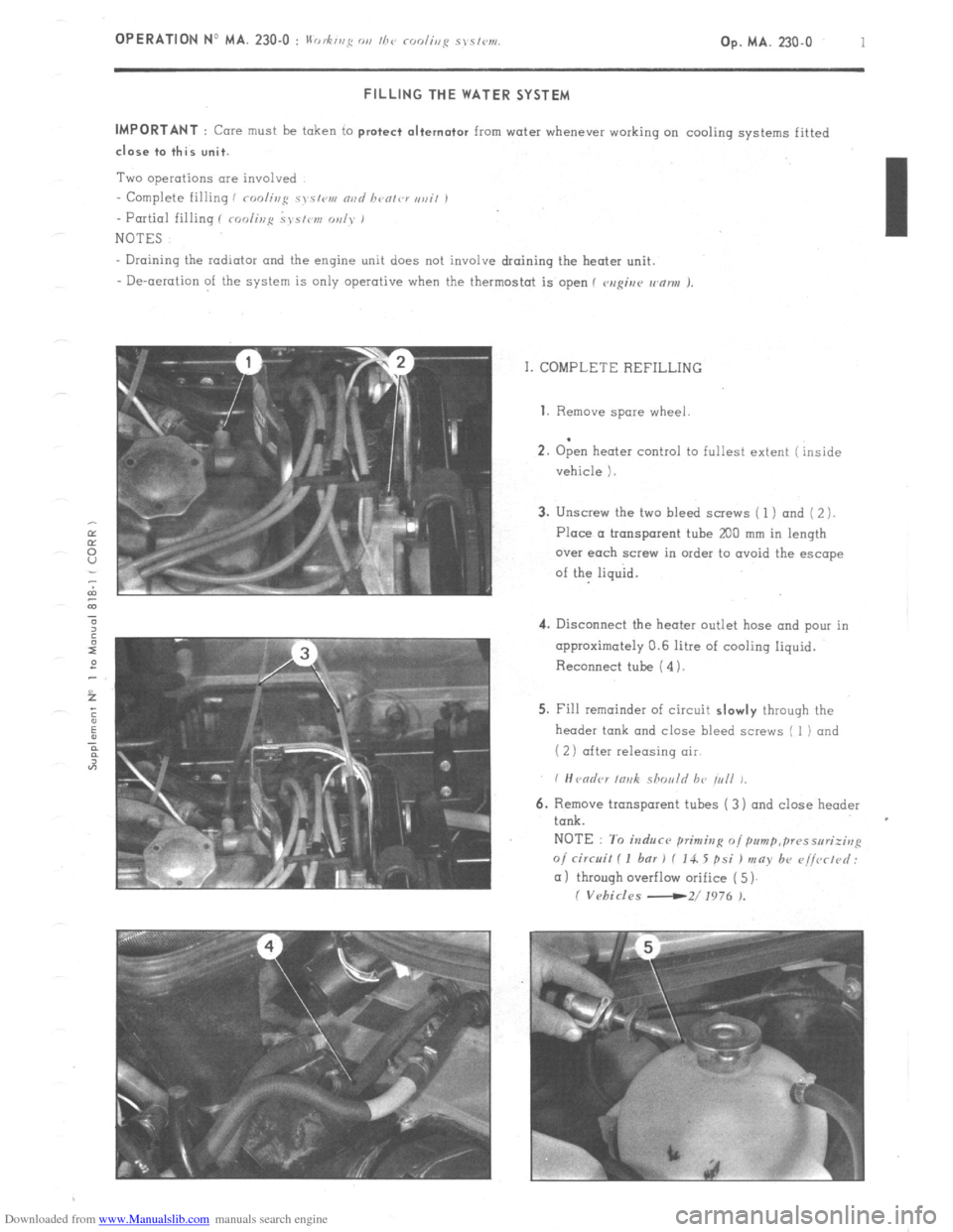
Op. MA. 230.0 1 FILLING THE WATER SYSTEM
IMPORTANT
: Core must be token to protect alternator from water whenever working on cooling systems fitted close to this unit.
Two operations are involved
- Complete filling i roolir~g c~s~<,v, nvd bvolvr ,,ail ,
- Partial filling I roolir,p ~J~S/IW, oul~* 1
NOTES
Draining the radiator and the engine unit does not involve draining the heater unit.
- De-aeration of the system is only operative when the thermostat is open 1 v,rgiur wnnu J.
I. COMPLETE REFILLING 1. Remove
spare wheel
.
2. Open heater control to fullest extent ( inside
vehicle 1.
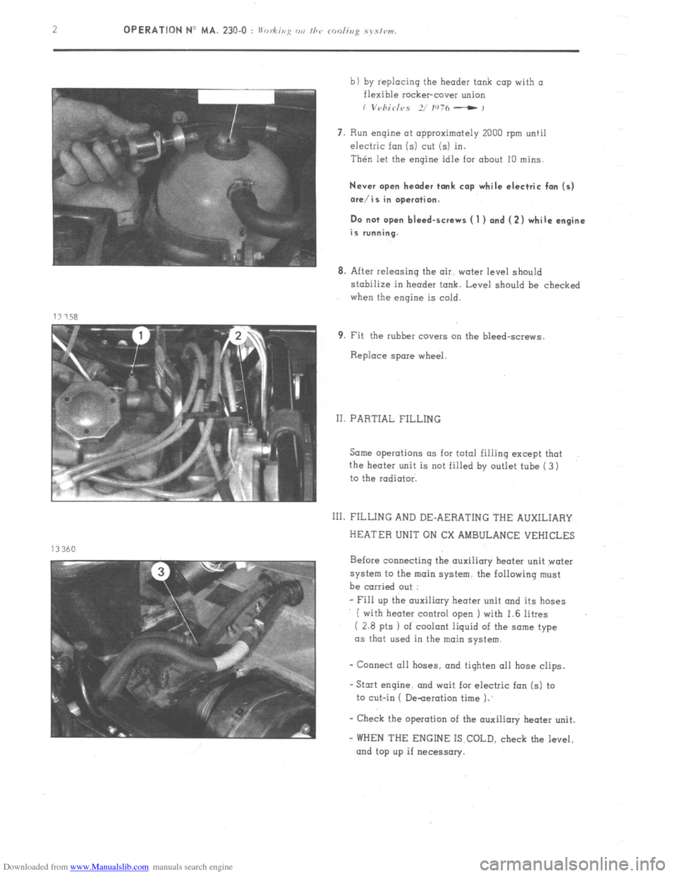
3. Unscrew the two bleed screws ( 1 ) and ( 2 ).
Place a tronsporent tube
200 mm in length
over each screw in order to ovoid the escape
of the liquid.
4. Disconnect the heater outlet hose and pour in
approximately 0.6 litre of cooling liquid.
Reconnect tube ( 4).
5. Fill remainder of circuit slowly through the
header tank and close bleed screws I 1) and
( 2) after releasing air
6. Remove transparent tubes ( 3) and close header
tank.
NOTE : To induce primitzg o/pum~,~~~sseri;irrp
o/ circuit I I bar 1 f 14. 5 psi ) may b+ r~i/vrtd:
(11 through overflow orifice ( 5)
I Vehicles -2/ 1976 ).
Page 179 of 394
Downloaded from www.Manualslib.com manuals search engine 2 OPERATION No MA. 230-O : II .h’ 0, fug Ol, I/7‘, rodir,p sys/w1.
b) by replacing the header tank cap with a
flexible rocker-cover union
I V~~/7id<~S 2/ IU7h - ,
7. Run engine at approximately 2000 rpm until
electric fan (5) cut (5) in.
Then let the engine idle for about 10 mins.
Never open header tank cap while electric fan (5)
ore/is in operation.
Do not open bleed-screws ( 1 ) and (2) while engine
is running.
8. After releasing the air. water level should
stabilize in header tank. Level should be checked
when the engine is cold.
9. Fit the rubber covers cm the bleed-screws.
Replace spare wheel.
II. PARTIAL FILLING
Same operations as for total filling except that
the heater unit is not filled by outlet tube ( 3)
to the radiator.
111. FILLING AND DE-AERATING THE AUXILIARY
HEATER UNIT ON CX AMBULANCE VEHICLES
Before connecting the auxiliary heater unit water
system to the main system. the following must
be carried out :
- Fill up the auxiliary heater unit and its hoses
( with heater control open I with 1.6 litres
( 2.8 pts 1 of coolant liquid of the some type
as that used in the main
system.
- Connect all hoses. and tiqhten 011 hose clips.
-Stat engine. and wait for electric fan (5) to
to cut-in ( De-aeration time 1.’
- Check the operation of the auxilioly heater unit.
- WHEN THE ENGINE IS COLD, check the level,
and top up if necessary.
Page 334 of 394
Downloaded from www.Manualslib.com manuals search engine Op. MA. 510-00 b 17 WIRING DIAGRAMS’FOR COOLING FAN AND AIR-CONDITIONING SYSTEM CONTROL
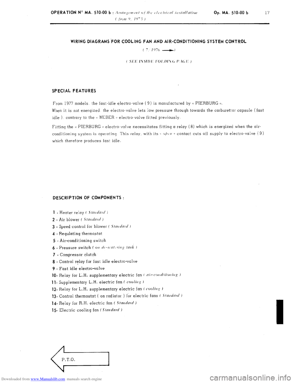
SPECIAL FEATURES
From 1977 models the fast-idle electro-valve ( 9) is manufactured by 1, PIERBURG 1).
When it is not enerqized the electro-valve lets low pressure through towards the carburettor capsule (fast
idle ) contrary to the (1 WEBER )) electromvalve fitted previously.
Fitting the N PIERBURG )) electro-valve necessitates fitting a relay (8) which is enerqized when the air-
conditioning system is operating This relay, with its c( o/)t/i 1) contact cuts off supply to electro-valve (9)
which therefore produces fast idle. DESCRIPTION OF COMPONENTS :
1
- Heater relay ( .s/o~/~/Q~c/ )
2 - Air blower ( .S~n~~dnr(i i
3 - Speed control for blower ( S/nr/clnrt/ J
4 - Regulating thermostat
5 - Air-conditioning switch 6
- Pressure switch ( 01, dc,-rt,cr/t,rit,,q lnr~k ) 7
- Compressor clutch
8 - Control relay for fast idle melectro-valve
9 - Fast idle electro-valve lo-
Relay for L.H. supplementary electric fan f nip-cor/rli/ior/illS ) 1
I- Supplementary L.H. electric fan ( foolir2~~ ) 12-
Relay for L.H. supplementary electric fan ( cooli~/g ) ?3-
Control thermostat ( on radiator ) for electric fans ( Stnr~d& )
14- Relay for R.H. electric fan ( Stmzdnrrl )
15 Electric cooling fan ( Stal?dn~/ )
Page 361 of 394
Downloaded from www.Manualslib.com manuals search engine AIR-CONDITIONING
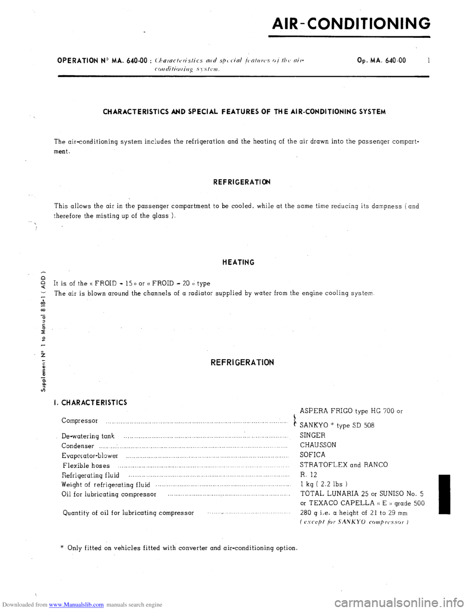
CHARACTERISTICS AND SPECIAL FEATURES OF THE AIR-CONDITIONING SYSTEM
The air-conditioning system includes the refrigeration and the heating of the air drawn into the passenger compart-
ment. REFRIGERATION
This allows the air in the passenger compartment to be cooled, while at the same time reducing its dampness (and
therefore the misting up of the glass ) HEATING
It is of the (( FROID - 15)) or (( FROID - 20 )) type
1 The air is blown around the channels of a radiator supplied by water from the engine cooling system.
&
co
5
3
t
E REFRIGERATION
E I. CHARACTERISTICS
ASPERA FRIGO type HG 700 or
Compressor
1 .
SANKYO * type SD 508
De-watering tank . SINGER
Condenser _.. ._..: _._...... . . . . . . . . . . . CHAUSSON
Evaporator-blower , SOFICA
Flexible hoses ..,_.,....,............................................................................... STRATOFLEX and RANCO
Refrigerating fluid . R. 12 Weight
of refrigerating fluid _..._.._._._..,_..__.................................................... 1 kg ( 2.2 lbs )
Oil for lubricating compressor TOTAL LUNARIA 25 or SUNISO No. 5
or TEXACO CAPELLA (( E )) grade 500
Quantity of oil for lubricating compressor ,
280 g i.e. a height of 21 to 29 mm
f
CJSCC,~~ ior SANKYO UIVI~WSSO~ J
* Only fitted on vehicles fitted with converter and air-conditioning option.
Page 367 of 394
Downloaded from www.Manualslib.com manuals search engine OPERATION No MA. 640-00 : (hnrnct~~tis~ics md special jenttrrvs of the nir-
coi~ditiouing systcw. 1 Op. MA. 640-00
7
VII. WIRING DIAGRAMS FOR COOLING FAN AND AIR-CONDITIONING SYSTEM CONTROLS
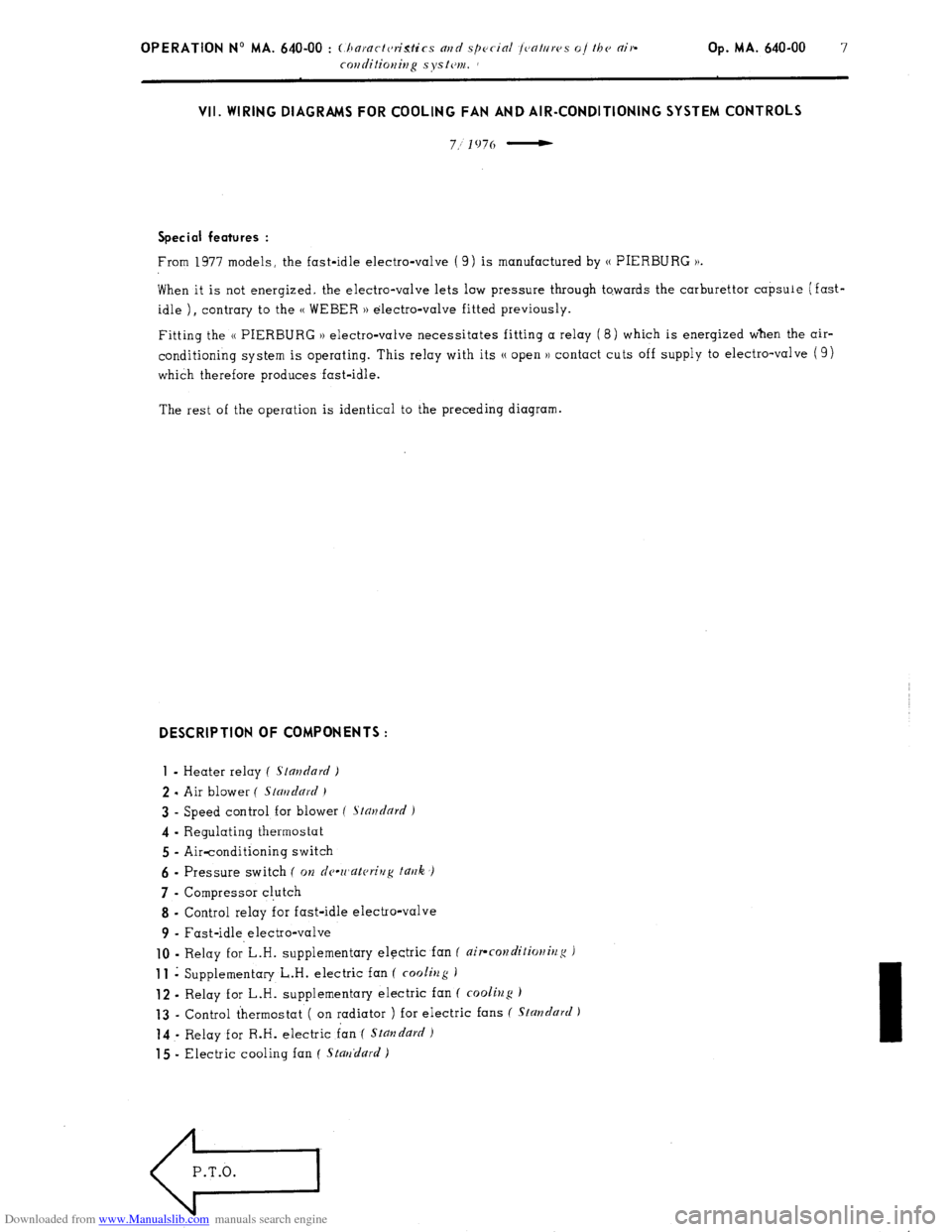
7.; 1976 - Special features :
From 1977 models, the fast-idle electro-valve ( 9) is manufactured by (( PIERBLJRG )).
When it is not energized. the electro-valve lets low pressure through to.wards the carburettor capsule (fast-
idle ) I contrary to the (( WEBER )) electro-valve fitted previously.
Fitting the (( PIERBURG )) electro-valve necessitates fitting a relay (8) which is energized when the air-
conditioning system is operating. This relay with its N open )) contact cuts off supply to electro-valve ( 9)
which therefore produces fast-idle.
The rest of the operation is identical to the preceding diagram. DESCRIPTION OF COMPONENTS :
1
- Heater relay ( standard )
2 - Air blower ( Stmdnrd )
3 - Speed control for blower f Stnudnrd )
4 - Regulating thermostat
5 - Air-conditioning switch
6 - Pressure switch ( on dc-wnkrivg t~rrk ,)
7 - Compressor cl.utch
8 - Control relay for fast-idle electro-valve
9 - Fast-idle electro-valve
10 - Relay f0r’L.H. supplementary electric fan ( air-rorzditio)litlg J 11
i Supplementary L.H. electric fan ( cooliug )
12 - Relay for L.H. supplementary electric fan ( cooling ) 13
- Control thermostat ( on radiator ) for electric fans ( Standard ) 14
- Relay for R.H. electric fan ( Stmzdurd 1
15 - Electric cooling fan ( Stnrrdurd )
e
P.T.O.