tow Citroen CX 1984 1.G User Guide
[x] Cancel search | Manufacturer: CITROEN, Model Year: 1984, Model line: CX, Model: Citroen CX 1984 1.GPages: 394
Page 170 of 394
Downloaded from www.Manualslib.com manuals search engine CHARACTERISTICS
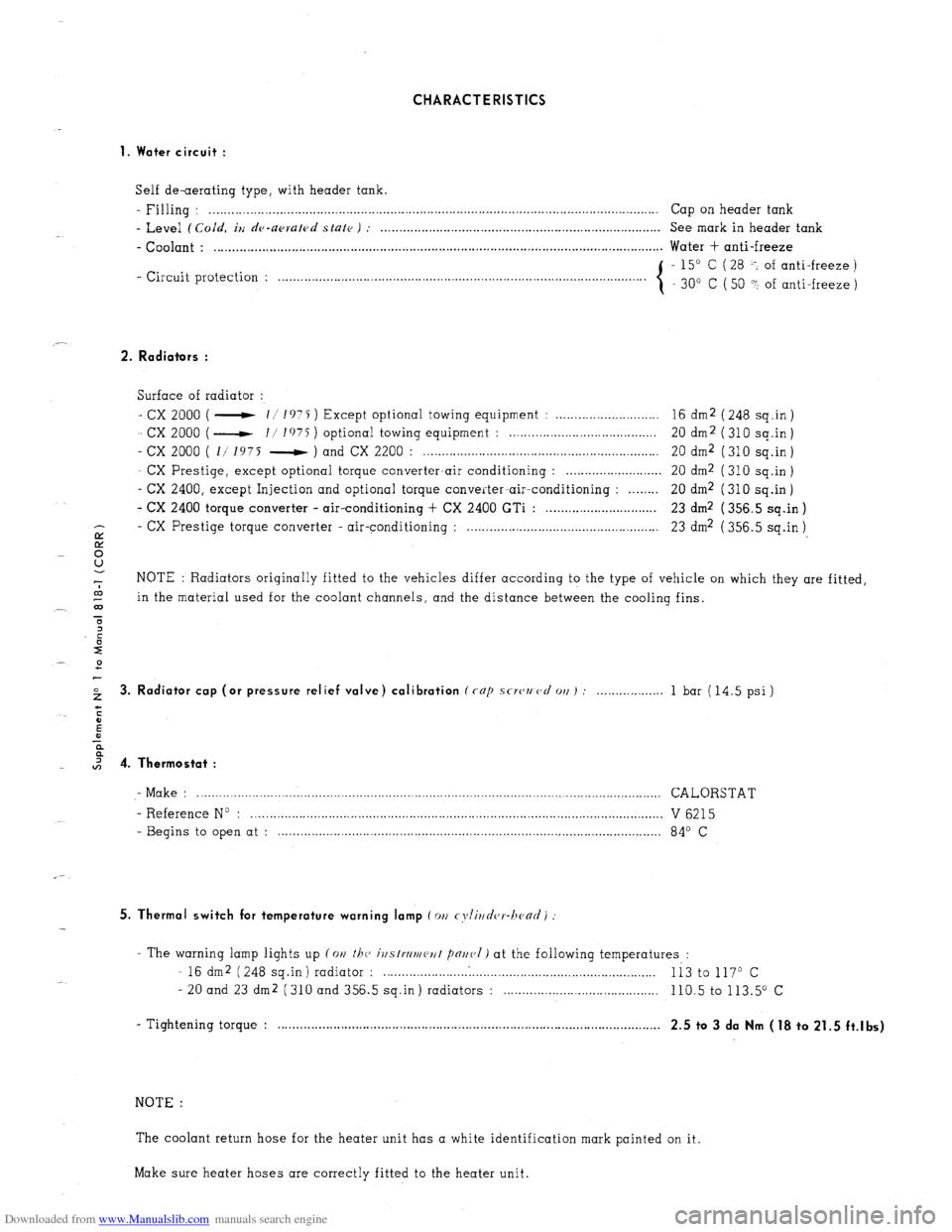
1. Water circuit :
Self de-aerating type, with header tank.
- Filling : . . . . . . . .._................................................................................................................ Cap on header tank
- Level (Cold, iu de-upruled state ) : . . . . . . . . . . . . . . . . . . . . . . . . . . . . . . . . . . . . . . . . . . . . . . . . . . . . . . . . . . . . . . . . . . . . . . . . . . . . See mark in header tank
- Coolant : . . . . . . . . . . . . . . . . . . . . . . . . . . . . . . . . . . . . . . . . . . . . . . . . . . . . . . . . . . . . . . . . . . . . . . . . . . . . . . . . . . . . . . . . . . . . . . . . . . . . . . . . . . . . . . . . . . . . . . . . .. Water + anti-freeze
- Circuit protection : - 15” C ( 28 -: of anti-freeze )
. . . . . . . . . . . . . . . . . . . . .
30” C ( 50 ? of anti-freeze )
2. Radiators :
Surface of radiator :
- cx 2000 ( - 11 1975 ) Except optional towing equipment : . . . . . . . . . . . . . . . . . . . . . . . . . . . . 16 dm2 ( 248 sq.in )
- cx 2000 ( - I/ I’)75 ) optional towing equipment : . . . . . . . . . . . . . . . . . . . . . . . . . . . . . . . . . . . . . . 20 dm2 (310 sq.in)
- cx 2000 ( 1/ 1975 - ) and CX 2200 : . . . . . . . . . . . . . . . . . . . . . . . . . . . . . . . . . . . . . . . . . . . . . . . . . . . . . . . . . . . . . . . . 20 dm2 ( 310 sq.in )
- CX Prestige, except optional torque converter-air conditioning : . . . . . . . . . . . . . . . . . . . . . . . . . . 20 dm2 ( 310 sq.in )
- CX 2400, except Injection and optional torque converter-air-conditioning : . . . . . . . . 20 dm2 (310 sq.in)
- CX 2400 torque converter - air-conditioning + CX 2400 GTi : . . . . . . . . . . . . . . . . . . . . . . . . . . . . . . 23 dm2 ( 356.5 sq.in )
- CX
E Prestige torque converter - air-conditioning : . . . . . . . . . . . . . . . . . . . . . . . . . . . . . . . . . . . . . . . . . . . . . . . . . . . . 23 dm2 ( 356.5 sq.in )
8
-7 NOTE : Radiators originally fitted to the vehicles differ according to the type of vehicle on which they are fitted,
co
_- 03 in the material used for the coolant channels, and the distance between the cooling fins.
T
2 3. Radiator cap (or pressure relief valve) calibration (rap scwzmcl 011) : . . . 1 bar (14.5 psi)
I 4. Thermostat :
- Make : .............................................................................................................................. CALORSTAT
- Reference No : ................................................................................................................ V 6215
- Begins to open at : ........................................................................................................ 84’ C
5. Thermal switch for temperature warning lamp (011 cyli~~d(,r-hc~ad)
- The warning lamp lights up (on the, ivstrrlmeut pnr~(,I) at the following temperatures :
- 16 dm2 (248 sq.in) radiator : . . . . . . . . . . . . .
Ii3 to 117O c
- 20 and 23 dm2 (310 and 356.5 sq.in) radiators : . . . . 110.5 to 113.5” c
- Tightening torque : . . . . . . . . . . . . . . . . . . . . . . . . . . . . . . . . . . . . . . . . . . . . . . . . . . . . . . . . . . . . . . . . . . . . . . . . . . . . . . . . . . . , . . . . . . . . . . . . . . . . . . . .
2.5 to 3 da Nm (18 to 21.5 ft.lbs)
NOTE :
The coolant return hose for the heater unit has a white identification mark painted on it.
Make sure heater hoses are correctly fitted to the heater unit.
Page 171 of 394
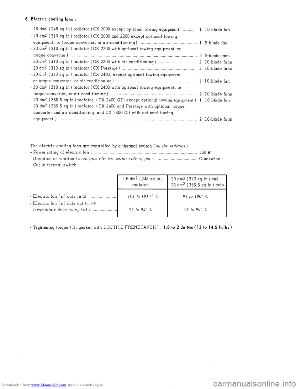
Downloaded from www.Manualslib.com manuals search engine 6. Electric cooling fans :
- 16 dm2 (248 sq.in ) radiator ( CX 2000 except optional towing equipment ) ,......... 1
- 20 dm2 (310 sq.in ) radiator (CX 2000 and 2200 except optional towing
equipment, or torque converter, or air-conditioning) . . . . . . . . . . . . . . . . . . . . . . . . . . . . . . . . . . . . . . . . . . . . . . . . 1
- 20 dm2 (310 sq.in ) radiator ( CX 2200 with optional towing equipment or
torque converter ) . . . . . . . . . . . . . . . . . . . . . . . . . . . . . . . . . . . . . . . . . . . . . . . . . . . . . . . . . . . . . . . . . . . . . . . . . . . . . . . . . . . . . . . . . . . . . . . . . . . . . 2
20 dm2 (310 sq.in ) radiator ( CX 2200 with air-conditioning) ,............................... 2
- 20 dm2 (310 sq.in) radiator ( CX Prestige) . . . . . . . . . . . . . . . . . . . . . . . . . . . . . . . . . . . . . . . . . . . . . . . . . . . . . . . . . . . . . . 2
- 20 dm2 (310 sq.in) radiator (CX 2400, except optional towing equipment
or torque converter, or air-conditioning ) . . . . . . . . . . . . . . . . . . . . . . . . . . . . . . . . . . . . . . . . . . . . . . . . . . . . . . . . . . . . . . . . . . . . 1
20 dm2 ( 310 sq .in ) radiator ( CX 2400 with optional towing equipment, or
torque converter, or air-conditioning ) . . . . . . . . . . . . . . . . . . . . . . . . . . . . . . . . . . . . . . . . . . . . . . . . . . . . . . . . . . . . . . . . . . . . 2
- 23 dm2 (356.5 sq.in ) radiator, ( CX 2400 GTi except optional towing equipment ) 1
- 23 dm2 (356.5 sq.in) radiator, (CX 2400 and Prestige with optional torque
converter and air~conditioning, and CX 2400 Gti with optional towing
equipment ) . . . . . . . . . . . . . . . . . . . . . . . . . . . . . . . . . . . . . . . . . . . . . . . . . . . . . . . . . . . . . . . . . . . . . . . . . . . . . . . . . . . . . . . . . . . . . . . . . . . . . . . . . . . . . . . . . . . . . . 2 1 O-blade fan
5-blade fan
5-blade fans
lo-blade fans
1 O-blade fans
1 O-blade fan
1 O-blade fans
10 blade fan
lo-blade fans
The electric cooling fans are controlled by a thermal switch (011 /he
radiator)
e Power rating of electric fan : . . . . . . . . . . . . . . . . . . . . . . . . . . . . . . . . . . . . . . . . . . . . . . . . . . . . . . . . . . . . . . . . . . . . . . . . . . . . . . . . . . . . . . . . 150 W
Direction of rotation ( S(J(‘IJ ~YOIII
c>lcctric ~/o/or side of /alI ) : . . . . . Clockwise
- Cut-in thermal switch :
1.6 dm2 (248 sq.in ) 20 dm2 ( 310 sq.in ) and
radiator 23 dm2 (356.5 sq.in,) rads
- Electric fan ( s ) cuts in at . . 101 to
103.5” c, 95 to loo0 c
-. Electric fan ( s ) cuts out (with
trmperatnw decreasing )
at : ._._._._._........... 9 5 to 920 c 95 to 9o” c
- Tightening torque (fit gasket with LOCTITE FRENETANCH ) : 1.8 to 2 da Nm ( 13 to 14.5 ft.lbs)
Page 172 of 394
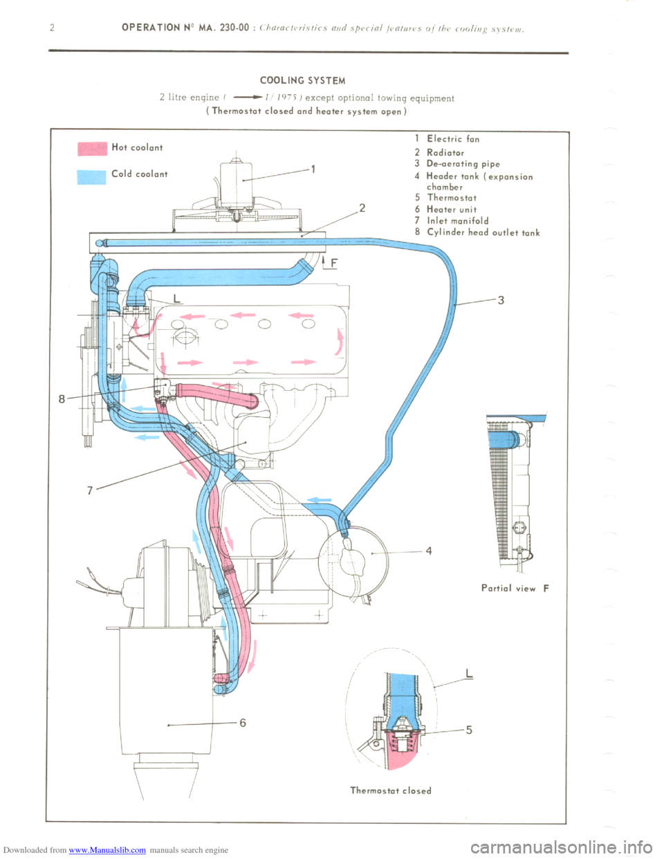
Downloaded from www.Manualslib.com manuals search engine COOLING SYSTEM
L litre enlyne f
-I l’r’i ) except optional towing equipment (Thermostat closed and heater system open)
Hot cool.n+
>Id coolant I Electric fan
2 Radiator
3 De-aerating pipe
4 Header tank (expansion
chamber
5 Thermostat
2 6 Heater unit
7 Inlet manifold
8 Cvlinder head outlet tank
Partial view F
II Thermostot closed
Page 207 of 394

Downloaded from www.Manualslib.com manuals search engine OPERATION No MA. 344-O : Adjusting thy gcarbor con/ro/s. Op. MA: 344.0 1
ADJUSTING THE GEAR LEVER
(I) the lever should be inclined approximately 3’
towards the rear in relation to the vertical axis
XX’ of the vehicle.
If not :
remove dust cover ( 1 ),
remove three screws ( 2 ),
shift cover ( 3 ) to obtain correct position of
gear lever.
NOTE : Should it be impossible to effect odjust-
merit by means of cover (3 ), make necessary
adjustment at control shaft hall joint (5 ).
Tighten three screws (2 ).
Refit dust cover (1 ). b)
the gear lever should be located in the longitu-
dinal axis YY’ of the vehicle.
If not :
= Adjust selector shaft boll joint (4) to obtain
this position.
NOTE :
When adjusting boll joints (4) 01 i 5) it is
imperative that the flats (v)
on each shaft ore properly aligned.
Page 241 of 394
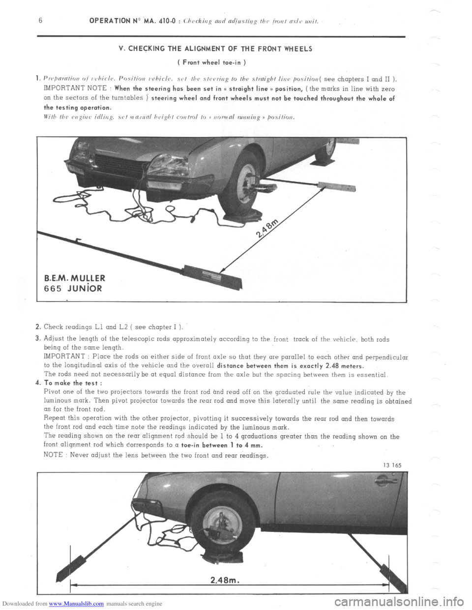
Downloaded from www.Manualslib.com manuals search engine V. CHECKING THE ALIGNMENT OF THE FRONT WHEELS
( Front wheel toe-in )
1. Prrpnmtion oi whirlr~. Positior,
whirls. set /he s,rering 10 Ihv straight line positim~( see chapters I and II )
IMPORTANT NOTE
When the steering has been set in I( straight line >) position, (the marks in line with zero
on the sectors of the turntables
1 steering wheel and front wheels must not be touched throughout the whole of
the testing operation.
2. Check readings Ll and L2 ( see chapter I ).
3. Adjust the length of the telescopic rods approximately according to the front track of the vehicle, both rods
being of the some length.
IMPORTANT : Place the rods on either side of front axle so that they are parallel to each other and perpendicular
to the longitudinal axis of the vehicle and the overall
distance between them is exactly 2.48 meters.
The rods need not necessarily be at equal distance from the axle but the spacing between them is essential.
4.
To make the test :
Pivot one of the two projectors towards the front rod hnd read off on the graduated rule thr value indicated by the
luminous mark. Then pivot projector towards the rear rod and move this laterally until the snne reading is obtained
as for the front rod.
Repeat this operation with the other projector, pivotting it successively towards the rear rod and then towards
the front
rod and each time note the readings indicated by the luminous mark.
The reading shown on the rem alignment rod should be 1 to 4 graduations greater than the reading shown on the
front alignment rod which corresponds to a
toe-in between 1 to 4 mm.
NOTE Never adjust the lens between the two front and rear readings.
13 165
Page 244 of 394
Downloaded from www.Manualslib.com manuals search engine OPERATION No MA. 4104 : (./ , k’ 1
ADJUSTMENT
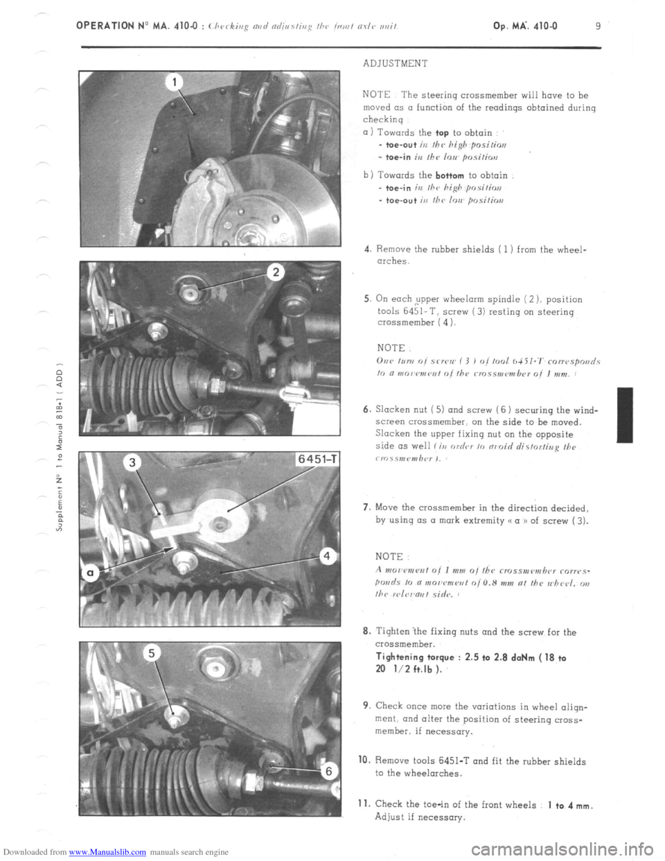
NOTE The steering crossmember will have to be
moved (IS a function of the readings obtained during
checkinq
01) Towards the top to
obtain
_ toe-out ir, Ihe hish positim
- toe-in irr the 10~ psitios
b) Towards the bottom
to obtain
.
toe-in in Ihr hi& posilins
- toe-out iu fhc IOU posilios
4. Remove the rubber shields ( 1 ) from the wheel-
arches.
5. On each ,upper wheelorm spindle (2 ). position
tools 6451-T, screw (3) resting on steering
crossmember ( 4 1.
NOTE.
6. Slacken nut ( 5) and screw (6 1 securing the wind-
screen crossmember. on the side to be moved.
Slacken the upper fixing nut on the opposite
side as well li,r order 10 nrmoid rlistorfina II><,
crr~.ss,nP”,b<~r ,,
7. Move the crossmember in the direct& decided,
by using (1s a mark extremity (( a u of screw ( 3).
8. Tighten ‘the fixing nuts and the screw for the
crossmember. Tightening torque : 2.5 ta 2.8 doNm ( 18 ta
20 l/2 ft.lb ).
9. Check once mew the variations in wheel aliqn-
merit. and alter the position of steering cross-
member. if necessary. 10.
Remove tools 6451-T and fit the rubber shields
to the wheelarches.
Adjust if necessary. 11.
Check the toe-in of the front wheels 1 to 4 mm.
Page 245 of 394
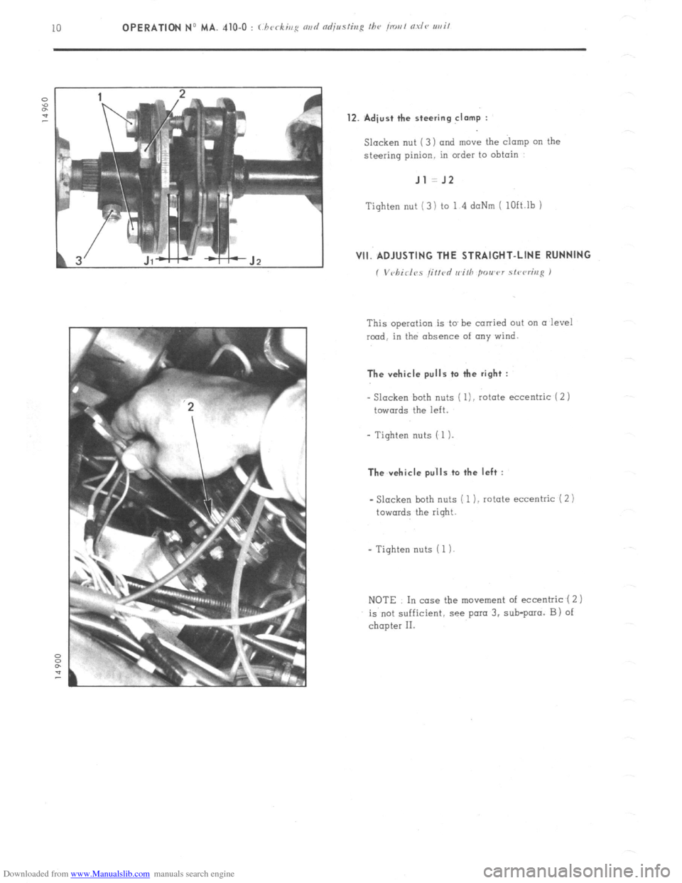
Downloaded from www.Manualslib.com manuals search engine 12. Adiust the steering clamp :
Slacken nut ( 3 ) and move the clamp on the
steering pinion. in order to obtain Jl =J2
Tighten nut (3) to 1 4 daNm ( lOft.lb 1 VII. ADJUSTING THE STRAIGHT-LINE RUNNING
( Vvhirlvs jirtd rr~ilh power stcvri1r.q )
This operation is to be
carried out on a level
rmd, in the absence of any wind. The vehicle pulls ta the right :
- Slacken
both nuts ( l), rotate eccentric ( 2 )
towards the left.
- Tighten nuts ( 1). The vehicle pu’lls to the left :
- Slacken both nuts ( 1 ), rotate eccentric i 2) towards
the right.
- Tighten nuts ( 1)
NOTE In case the movement of eccentric ( 2 1
is not sufficient, see para 3. sub-para. B) of
chapter II.
Page 250 of 394
Downloaded from www.Manualslib.com manuals search engine Op. MA. 420.0 1
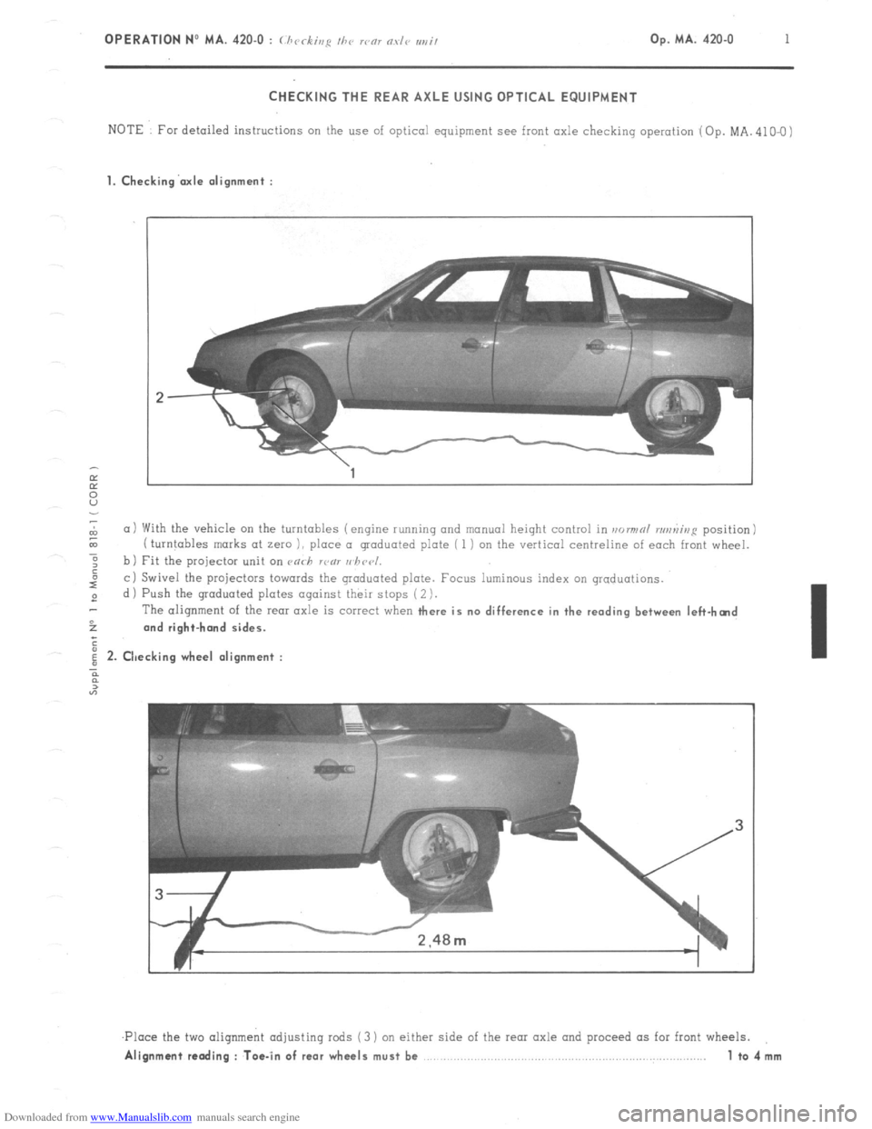
CHECKING THE REAR AXLE USING OPTICAL EQUIPMENT
NOTE For detailed instructions on the use of optical equipment see front axle checking operation (Op. MA. 410-O)
1. Checking’axle alignment :
L
(11 With the vehicle on the turntables (engine running and manual height control in normnl runniup position)
& ( turntables marks at zero 1, place a graduated plate ( 1 i on the vertical centreline of each front wheel.
-6
: b) Fit the projector unit on ca<-h rcnl uhccl.
I”
c i Swivel the projectors towards the graduated plate. Focus luminous index on graduations.
2 d ) Push the graduated plates against their stops ( 2 ).
The alignment of the
rear axle is correct when there is no difference in the reading between left-hcnd
52 and right-hand sides.
;
i 2. Checking wheel alignment :
n
2
“7
,Ploce the two aliqnmeht adjusting rods (3 ) on either side of the rear axle and proceed as for front wheels.
Alignment reading : Toe-in of rear wheels must be 1 to4mm
Page 267 of 394
Downloaded from www.Manualslib.com manuals search engine 6
OPERATION No MA. 440-00 : (.hnrcrc-tcrislics nrtd .s/)oc-in/ /c~n/trr(~s o/ I/I(~ .s/(,(zri,~g
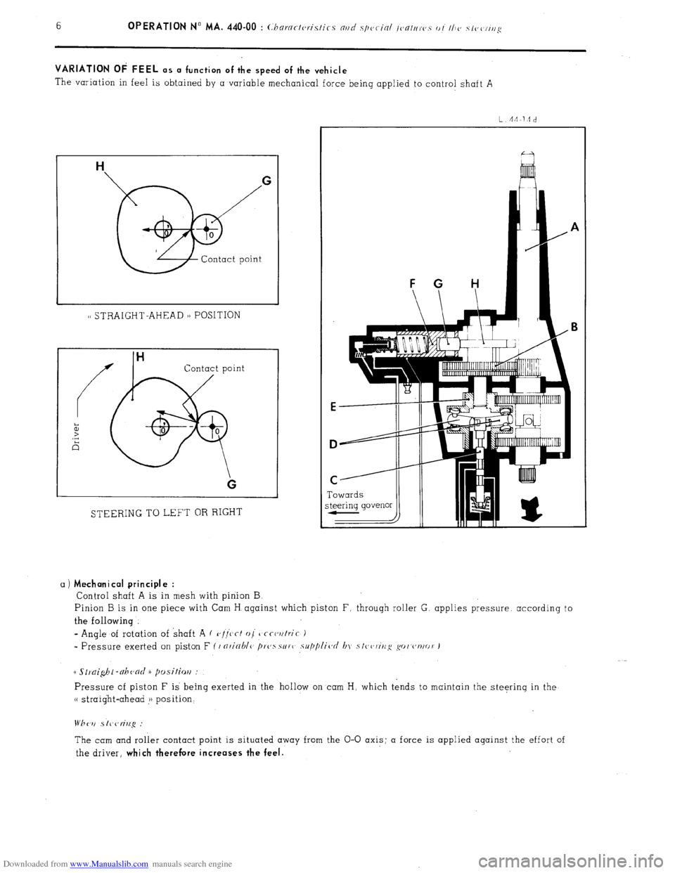
VARIATION OF FEEL as a function of the speed of the vehicle
The variation in feel is obtained by a variable mechanical force being applied to control shaft A
1~ STRAIGHT-AHEAD 1) POSITION
Contact point
STEERING TO LEFT OR RIGHT Towards
a)
Mechanical principle :
Control shaft A is in mesh with pinion B
Pinion B is in one piece with Cam H against which piston F, through roller G. applies pressure. according to
the following
- Angle of rotation of shaft A ( r,//‘c’cf oj
tjcct,utric )
* Pressure exerted on piston F ( I nricrhlc> /)r(,ssur( supplic~d In stc,~,ririg go('~'nlor J
Pressure of piston F is being exerted in the hollow on cam H, which tends to maintain the steering in the
(( straight-ahead !j position‘
The cam and roller contact point is situated away from the O-O axis; a force is applied against the effort of
the driver,
which therefore increases the feel.
Page 268 of 394
Downloaded from www.Manualslib.com manuals search engine d
m
.-
0
2
f Op. MA. 440-00
7 -
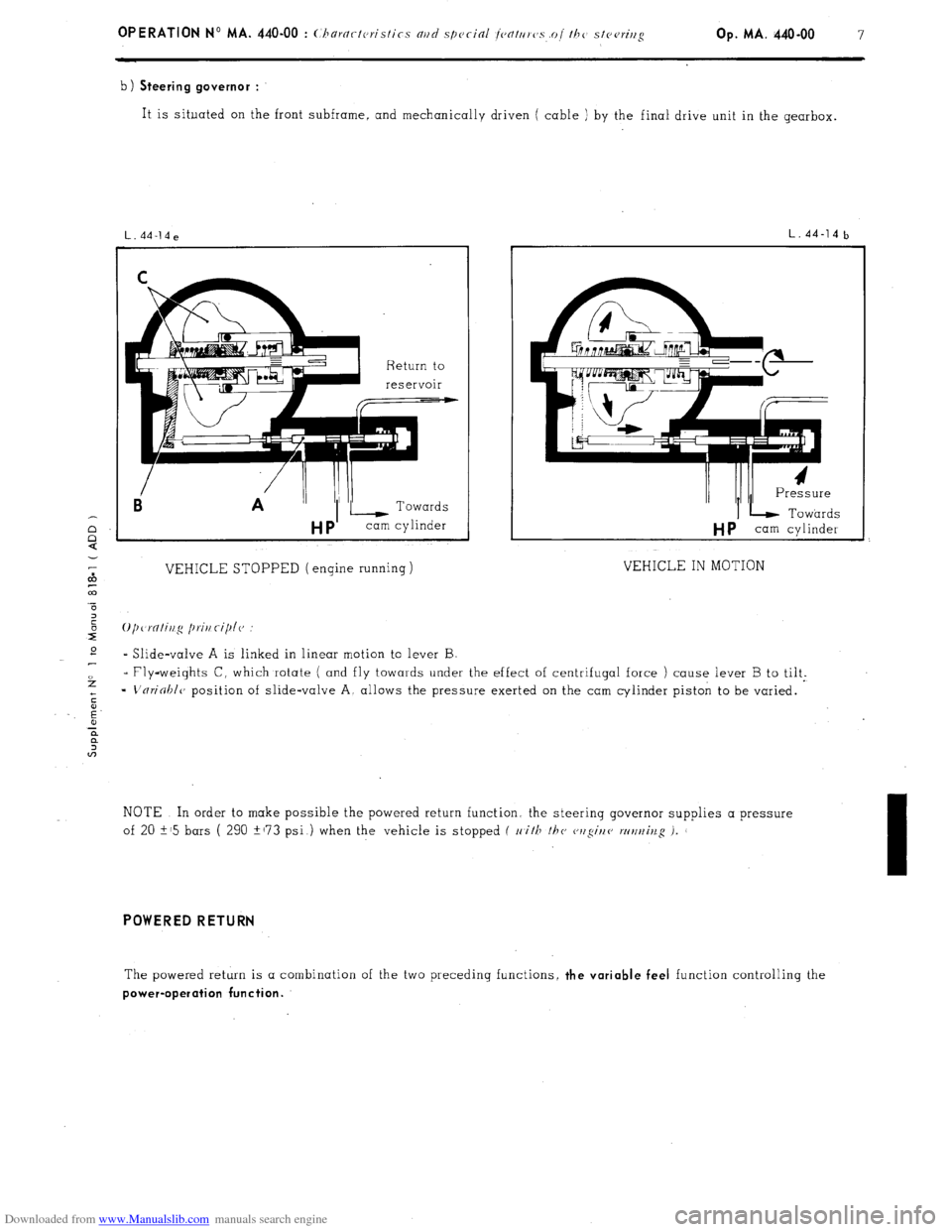
b) Steering governor :
It is situated on the front subframe, and mechanically driven ( cable ) by the final drive unit in the gearbox.
Ei A ”
VEHICLE STOPPED (engine running)
L.44-14b
I/ /II I Pressure
IL Towards
HP cam cylinder
VEHICLE IN MOTION
* Slide-valve A is linked in linear motion to lever B
- Fly-weights C, which rotate ( and fly towards under the effect of centrifugal force ) cause lever B to tilt.
=
L'nrioblc, position of slide-valve A, allows the pressure exerted on the cam cylinder piston to be varied.
NOTE In order to make possible the powered return function. the steerinq governor supplies a pressure
of 20 i-15 bars ( 290 +173 psi ) when the vehicle is stopped f 11
i/F /hc cwgir/e wt/t~iv.g i.
I
POWERED RETURN
The powered return is a combination of the two preceding functions, the variable feel function controlling the
power-operation function.