oil level Citroen CX 1984 1.G Workshop Manual
[x] Cancel search | Manufacturer: CITROEN, Model Year: 1984, Model line: CX, Model: Citroen CX 1984 1.GPages: 394
Page 165 of 394
Downloaded from www.Manualslib.com manuals search engine OPERATION No MA. 220-O : (.hrrkinfi Ih e oil pr~ssrrrc m the rehicle Op. MA. 220.0 1
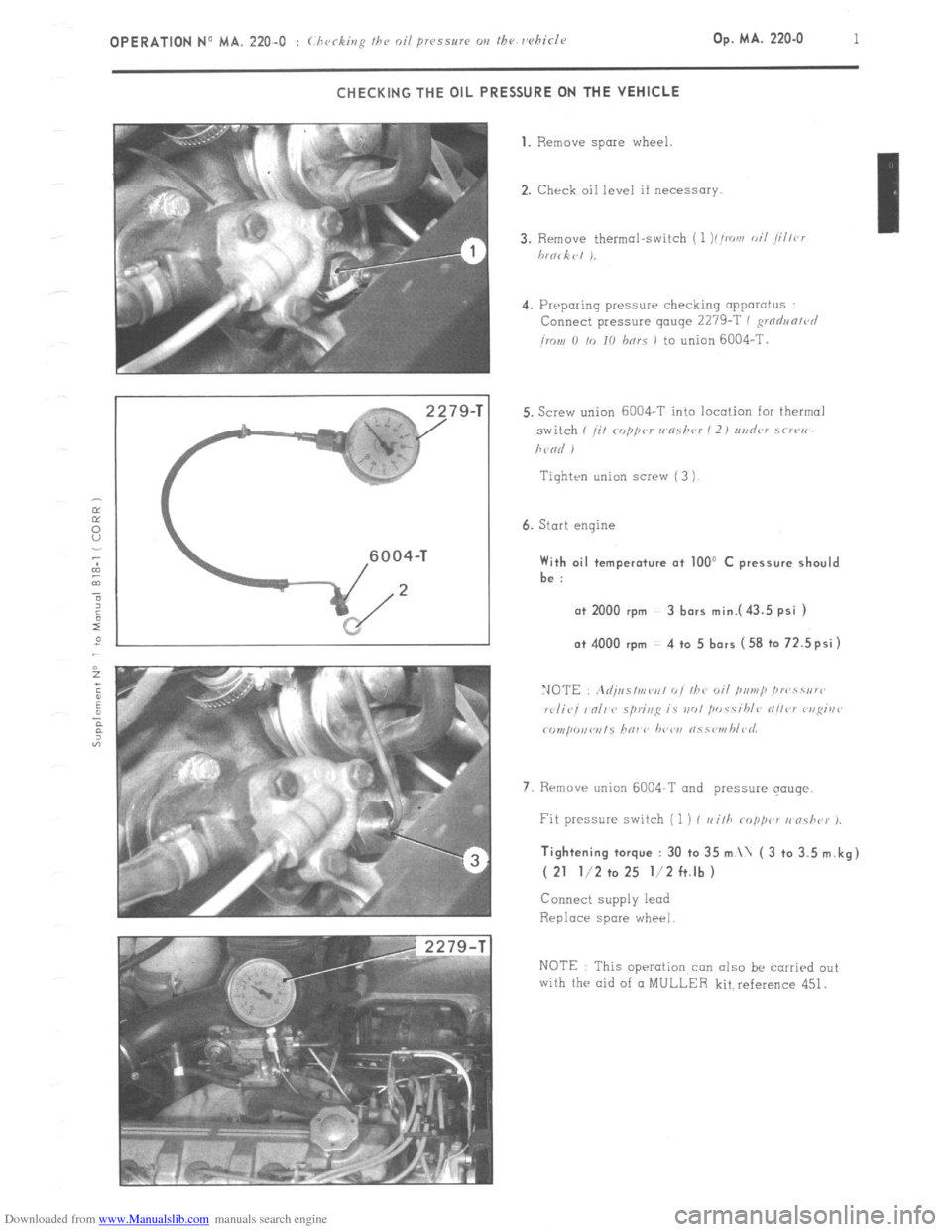
CHECKING THE OIL PRESSURE ON THE VEHICLE
79-T 1. Remove spare
wheel.
2. Check oil level if necessary.
4. Preparing pressure checking apparatus
Connect pressure gauge 2279-T ( ,wdun/r~l
imn 0 /o IO hnrs 1 to union 6004-T.
Tiqhten union screw ( 3 )
6. Start engine With oil temperature at 100’ C pressure should
be :
a+ 2000 rpm 3 bars mini43.5 psi ) o+ 4000 rpm 4 to 5 bars (58 to 72.5psi)
7. Rrmave union 6004-T and pressure qouqe. Tightening torque : 30 to 35 m \ ( 3 to 3.5 m.kg)
( 21 l/2 to 25 l/2 ft.lb )
Connect supply lead
Replace spare wheel
NOTE This operation con also be carried out
with the aid of CI MULLER kit,reference 451.
Page 168 of 394
Downloaded from www.Manualslib.com manuals search engine Op. MA. 221-O 3 -
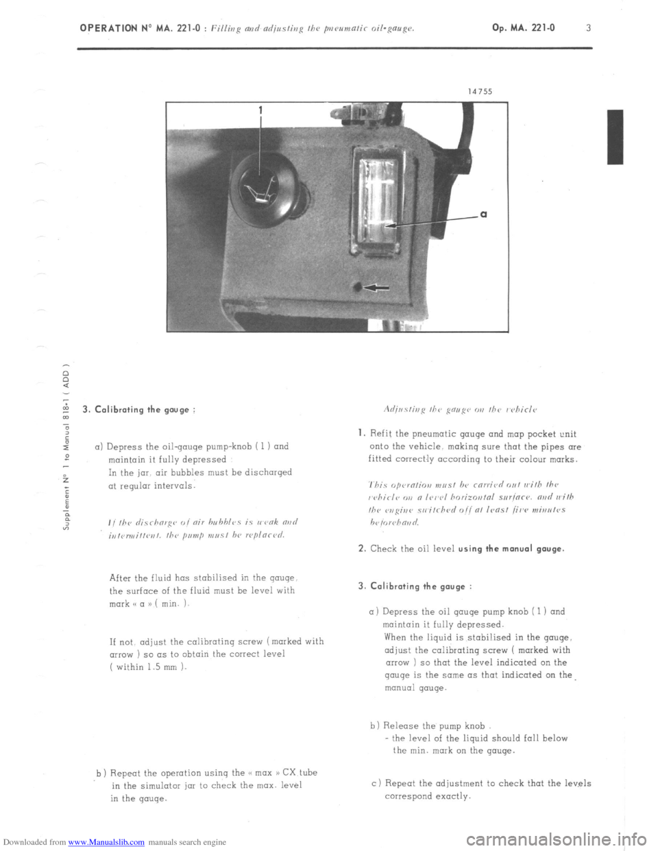
5 3. Calibrating the gouge :
”
6
I
a) Depress the oil-gouge pump-knob i 1) and
:
maintain it fully depressed
f In the jar. air bubbles must be discharged
; at regular intervals.
:
u
P
F
“3 , , ,hr ,I;.7 rhorg<~ ,, I nir hn hhlcs is I, vnk rind
;,,,<,r,,,i,,l~r,,. the primp m,, 51 hl, rcplnrl~d.
After the fluid has stabilised in the gauge
the surface of the fluid must be level with
mark o a a) ( min. i-
If not. adjust
the calibrating screw (marked with
(IIIOW ) so as to obtain the correct level
( within 1.5 mm 1.
b ) Repeot the operation using the << max a) CX tube
in the simulotar jar to check the max. level
in the gauge. 3. Calibrating the gauge :
a) Depress
the oil qauqe pump knob ( 1 1 and
maintain it fully depressed.
When the liquid is stabi!ised in the gouge,
adjust the calibrating screw 1 marked with
arrow ) so that the level indicated on the gauge
is the same as that indicated on the
manual gauge.
b) Release the pump knob
- the level of the liquid should fall below
the min. mark on the gauge.
c) Repeat the adjustment to check that the levels
correspond exactly.
Page 340 of 394
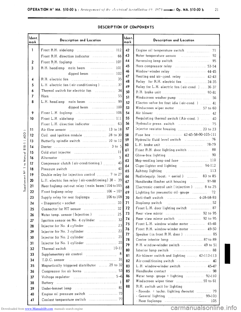
Downloaded from www.Manualslib.com manuals search engine OPERATION No MA. 510-00 b : A,.,.N//~w~/w/ of I/J<, c~l~~clriccrl iti7tollnliou (0 1075 -i Op. MA. 510-00 b 21 DESCRIPTION OF COMPONENTS
dent.
lark Description and Location Ident.
mark Description and Location
1
Front R.H. sidelamp ............................ 112 42
Engine oil temperature switch 71 ...............
Front R.H. direction indicator .... ... .........
66 43 Water temperature sensor .... .............. 92
2 Front R.H. foglamp 107 44 Reversing lamp switch ................... 95
..................... ....... ....
3 R.H. headlamp main beam
;:: :: Horn compressor relay ..................... 53-54
............... ....
dipped beam Window- winder relay .................. 44-45
......................
47
Heating and air-cond. relay ...............
4 R.H. electric fan ............................... 35 42-43
48
.............. 34-35
5 LH electric fan ( air--conditioning ) Relay for R.H. electric fan
........ 37 49
Relay for L.H. electric fan (air-cond. ) ..... 36-37
6 Thermal switch for electric fan .............. 34 50
R.H. brake unit
........... 80-81
......... ............
7 Horn
....................................
.......... ..... 55 51
Widscreen washer pump .............. .... 56
8 L.H. headlamp main beam ........... ..........
gg 52 Electra-valve for fast idle (air-cond. ) ......... 41
dipped beam ......................
100 53
Windscreen wiper motor ............. 57 to 60
9 Front L.H. foglamp ... . ...............................
106 54
Air blower ..............
........... ..... ........... 42 10
Front L.H. sidelamp ......................... ... ... .. 111 55 Regulating thermal switch (Air-cond. ) .... 40
Front L.H. direction indicator
63 56 ................... Hydraulic press. switch .......................
75 11
Air-flow sensor 13 to 18 57
........................... ... Injector resistor housing .................... .20 to 23 12
Coil. and ignition module
28 to 30 58 Fuse box ............................ 42-45-58-90-105-l 11
................. 13
Butterfly spindle switch 10 to 12 S9 Hydraulic fluid level switch ...................... 76
.................... 14
Starter 3 t0 5 6o L.H. brake unit ........................ 78-79
..........................................
88 15
Cold start injector 11 61 Front R.H. door lighting switch ....... ....
.................................. 16
Alternator 5 62 Glove-box lighting ................................ 90
...........
....... ..................... ....... 17
Compressor clutch ( air-conditioning ) 40 63 Map-reading lamp and fuse ............... ..... ... 110
.........
64 18
Pressure switch 40 Cigar-lighter and lighting ...................... 94-l 12
........................................
65 Ashtray lighting 113 ..................................... 19
Double relay for injection control 7 to 27 ............ 66
Radio(equip. locat. t aerial ) .......... 83 to 85
20 L.H. electric fan relay (air-conditioning) 38 = 39 67
Handbrake flasher unit housing .............. 97-98 21
Rear foglamp cut-out relay (main beam) 104 to 105 68
Electronic control unit (injection ) ....... 8 to 25
22 Front foglamp relay ....................... .. 106 - 107 69
Lighting for pneumatic oil- gauge .............. 72
23
Supply relay for rear foglamps ............ 106 to 108 70
Anti-theft switch ............................ 4-28-58-93 24
u Diagnostic )) socket 52 ......... ....... ... ..... ........ 33 71 Stoplamp switch ...................................... 25
Connector for HT sensor 72 ................... 87
....................... 32 Front L.H. door lighting switch 26
Water temp. sensor ( Injection ) Rear view mirror ............................ 92 to 95
... 25 73
27
Ignition sensor on No. 4 cylinder 32 74 Rear view mirror switch ................... 92 to 95
............. 28
Injector for No. 4 cylinder ...................... 23 75 Front L.H. window winder motor .......... 45-46 29
Injector for No. 3 cylinder 22 76 Front R.H. window-winder motor .............. 49-50
...........................
......................... 85 30
Injector for No. 2 cylinder 21 77 Speaker ( in front R.H. door )
......................... 78 Centre interior lamp ............................... 87 to 89 31 Injector for No. 1 cylinder 20 ............................. 79 R H. window-winder switch .................... 49 to 51 32 Thermal switch
........... .......................... 10-11 8 o
Interior lamp switch .................... ................ 88
33 Supplementary air control ............................
8 81
Air-blower switch and lighting .......... 42-112-113 34 T.&c.
SenSOr ........................................... 31 82 Air-conditioning switch ............... ............ 40
35
Magnetically triggered distributor ........ 29 to 32 83
L.H. window-winder switch .....................
45-47 36
Compressor for air horns ............. ..... ......... 53 85 Handbrake contact ......................................... 98 37
Voltage regulator 5-6 86 Water temp. gauge + lighting ..................
92-110
....................................... 38
Battery 1 87 Windscreen wiper timer
.......................... 59 to 61
....................................................... 39
40
41
Under-bonnet lamp ........................................ 81 88 R.H. switch unit for lighting
Engine oil pressure switch 73 - Speedo. t tacho. lighting rheostat ............ 79
............................
99-103
Coolant temperature switch 77
- General lighting ................................
....... ....................
- Rear foglamps ..................................... 105
Page 371 of 394
Downloaded from www.Manualslib.com manuals search engine II. PRECAUTIONS TO BE TAKEN WHEN WORKING ON THE AIR-CONDITIONING SYSTEM
a) It is imperative to wear goggles
b ) Do not smoke R 12 fluid,in the presence of a flame turns into a toxic gas.
c) Never heat any section of the refrigerating system.
d) Never switch on the refrigerating system if both electric cooling fans are not connected
e ) Never check the compressor oil level without first having drained the refrigerating circuit.
f ) Never use any oil other than TOTAL (( LUNARIA 25 H, SUNISO No 5 or TEXACO CAPELLA (( E 1) grade 500
g ) Never use refrigerating fluid other than R.12.
NOTE Refrigerating fluid may- be sold under different names : FORANE (( 12 )), FLUGENE (( 12 ))! FREON ((12 ))
( the most important feature is the number (( 12 H which defines the fluid’s properties ).
IMPORTANT NOTES
A. The compressor
MUST NEVER b e switched on when the circuit has been drained of its refrigerating fluid.
during work ‘being carried out in the workshop. for example,. Indeed, in these conditions,
the compressor
would be functioning in air, and would deteriorate rapidly.
‘Consequently, in case of an exchange of compressor necessitating draining the system of its refrigerating
fluid, in a workshop not equipped with the necessary equipment for refilling ( SOGEV equipment )
IT IS
IMPERATIVE,
before driving the vehicle to another workshop equipped with the special equipment. to carry
out the following
- To leave the blanking plugs on the compressor. in order to avoid ingress of air ( the new compressor contains
refrigerating fluid ).
- To blank the intake and outlet hoses and to fix them tempororily.
- Todisconnect the supply lead to the electro-magnetic compressor clutch
( lead with white sleeve ).
NOTE : We remind you that if the circuit has been in contact with the atmosphere, it is necessary to replace
the de-watering tank, and the compressor oil.
B. Slight oil seepage is permissible at the front bearing of the air-conditioning compressor.
Compressors showing such a seepage, and being replaced OS a result, will not be accepted under warranty.
Ill. TIGHTENING TORQUES FOR THE UNIONS IN THE CIRCUIT :
( Oil the union threads with TOTAL LUNARIA 25 before fitting )
On the compressor Intake union : 5/8” 3.45 to 4.3,daNm ( 25 to 31 ft.lb )
Outlet union l/2”’ 2.9 to 3.75 daNm ( 21 to 27 ft.lb )
On the condenser Input union l/2” 4.85 to 5.5 daNm ( 35 to 39 3/4 ft.lb )
Output union : 3/ 8” 2.7 to 3.3 daNm ( 19 l/2 to 23 3/4 ft.lb )
On-de-watering tank : Unions : 3/8” 2.1 to 2.5daNm ( 15 l/4 to 18 ft.lb )
On : Input union evaporator : 3/8” 2.1 to 2.5 daNm ( 15 l/4 to 18 ft.lb )
Output union 5/8” 3.45 to 4.3 daNm ( 25 to 31 ft.lb )
Page 373 of 394
Downloaded from www.Manualslib.com manuals search engine 4 OPERATION No MA. 640.0 : ( ht.< k;nS our/ ndj,,~/ir,~ I/><, ni~.rr,r,r/i/ior,i,,F sm,<,,,,.
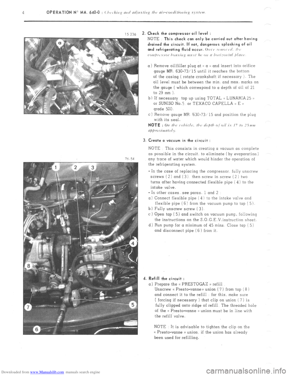
,s ~16 2. Check the ccmpress~r oil level :
76.54
NOTE This check con only be carried out after having
drained the circuit. If not, dangerous splashing of oil
and refrigerating fluid occur. 0vrs rowed vd. I/,<’
rornprc ‘i YC,l hr ,I,. Yi,,S I,,,, s, /w
gauge MR. 630-73/ 15 until it reaches the hottam
of the casing ( rotate crankshaft if necessary 1. The
oil level must be between the min. and max. marks on
the qauqe ( which correspond to a depth of oil of 21
to 29 mm ).
b I If necessary top up using TOTAL (< LUNARIA 25 ),
or SUNISO No.5 01 TEXACO CAPELLA << E )a
grade 500.
c) Remove gouge MR ‘630-73/ 15 and position the plug
with its seal.
3. Create a V(IEYU~ in the circuit :
NOTE This consists in creotinq a vacuum as complete
as possible in the circuit. to eliminate (by evaporation j
any trace of water which
would hinder the operation of
the refrigerating system.
- In the case of replacing the compressor. fully unscrew
screws ( 2 1 and ( 3 1 then screw in screw ( 2 ) two
turns after having connected flexible pipe ( 4) to the
intake valve.
* In other cases see paras. 1 and 2
a) Connect flexible pipe ( 4 i to the intake valve and
flexible pipe ( 6 1 from the vacuum pump to top ( 5 1.
b) Fully unscrew screw ( 3 1.
c ) Open tap [ 5) and switch on vacuum pump. following
the instructions on the S.O.G.E.V.instruction sheet.
di Run pump for a minimum
of 45 mins. Close tap ( 5)
and disconnect pipe ( 6 1 from it.
4. Refill the circuit :
a) Prepare the <( PRESTOGAZ n refill
Unscrew cf Presto-vanneu union ( 7 ) from tap ( 8 1
and connect it to the refill for this. make sure
I forcing if necessary ) that clip on union ( 7) is
fully clipped onto ridge of refill The threaded hole
of the o Presto-vanne )a union must be in line with
the refill valve.
NOTE It is advisable to tighten the clip on the
o Presto-wane >) union. if the union has already
been used for refilling.
Page 375 of 394
Downloaded from www.Manualslib.com manuals search engine 6
OPERATION No MA. 640-O : ( hvrsi~/p nsd ndj/w/isyc /I><, nirr~,s~l;/io,,i,,,~ syc,<,,,,
B. VEHICLES FITTED WITH A SANI(Y0 COMPRESSOR
NOTE Filling operations on CI vehicle fitted with a
and differ from the (< ASPERA-FRIGO 1) compressor only in as much as there are no screws for opening and closing
the valves.
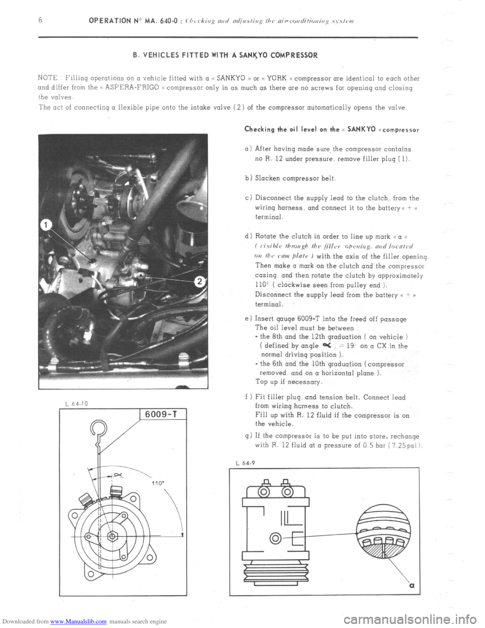
The act of connecting a flexible pipe onto the intake valve (2) of the compressor automatically opens the valve. Checking the oil level on the cc SANKYO ~ncompressor
(11 After having made’swe, the compressor contains
no R. 12 under pressure, remove filler plug ( 1).
b) Slacken compressor belt
cj Disconnect the supply lead to the clutch, from the
wiring harness. and connect it to the battery<, + >)
terminal.
d) Rotate the clutch in order to line up mark ,< a ))
( visihlc~ tllrou~h Ihv /i/ler
opvui,,p. nad lorn/~~d
w I/TV rnw flnle ) with the axis of the filler opening.
Then make a mark on the clutch and the compressor
co-sing. and then rotate the clutch by opproximotely
110’ ( clockwise seen from pulley end ).
Disccninect the supply lead from the battery <( + )a
terminal.
e) Insert gouge 6009-T into the freed off passage
The oil level must be between
- the 8th and the 12th graduation ( on vehicle )
( defined by angle aC = 19. on a CX in the
normal driving position ).
- the 6th and the 10th graduation (compressor
removed. and on a horizontal plane ).
Top up if necessary.
f 1 Fit filler plug, and tension belt. Connect iead
from wiring hcrness to clutch.
Fill up with R. 12 fluid if the compressor is on
the vehicle.
g) If the compressor is to be put into store. rechange
with R. 12 fluid at o pressure of 0.5 bar (7.25psi)
L 64.9
Page 391 of 394
Downloaded from www.Manualslib.com manuals search engine 1
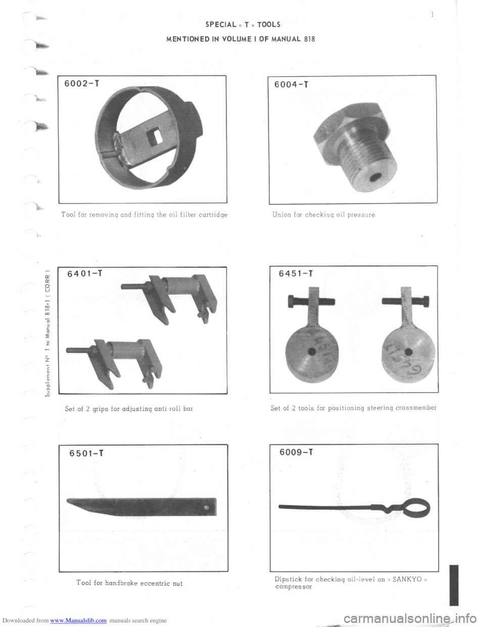
SPECIAL i< T ,, TOOLS
MENTIONED IN VOLUME I OF MANUAL 818
6002-
Tool for removing and fittinq the oil filter cortridqe
6401-T
Set of 2 grips for adjusting anti-roll bar
6501-T
Tool for honibrake eccentric nut
6004-T
Union for checking oil pressure
6451-T
Set of 2 tools for positioning steering crossmember
6009-T
Dipstick for checking oil-level on SC SANKYO 1)
compressor
I