stop start Citroen CX 1984 1.G Workshop Manual
[x] Cancel search | Manufacturer: CITROEN, Model Year: 1984, Model line: CX, Model: Citroen CX 1984 1.GPages: 394
Page 92 of 394
Downloaded from www.Manualslib.com manuals search engine OPERATION No MA. 142-O SD : (I k’ II c ,r,g m,d or/j,,r/ii,,~ /he m/i /dllllior, 5, Cl<‘,,i Op. MA. 142-O SD 1
f SIi’III)ISH \IAKKl:‘/ ,‘1,,,( 1.1’) ,
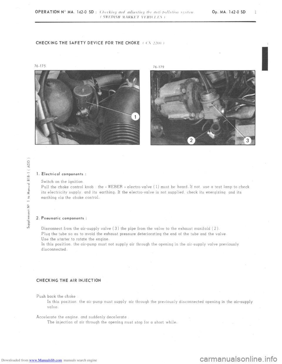
CHECKING THE SAFETY DEVICE FOR THE CHOKE i ( ?XO ,
2 1. Electrical components :
z
a Switch on the ignition
4 Pull the choke control knob the CC WEBER a) electto-valve ( 1) must be heard. If not use a test lamp to check
its electricity supply and its earthing. If the electro-valve is not supplied. check its energizinq and its
2
earthinq via the choke control.
5
;
E
; 2.P neurotic components :
?
“7
Disconnect from the air-supply valve ( 3 ) the pipe from the valve to the exhaust manifold ( 2 j
Plug the tube so as to avoid the exhaust pressure deteriorating the end of the tube and the valve
Use the starter to rotate the engine.
In this position the air-pump must not supply air through the opening in the air-supply valve previously
disconnecied.
CHECKING THE AIR INJECTION
Push bock the choke
In this position the air pump must supply air throuqh the previously disconnected opening in the air-supply
valve.
Accelerate the enqine. and suddenly decelerate
The injection of air through the openinq must stop for a short while.
Page 94 of 394
Downloaded from www.Manualslib.com manuals search engine CHECKING THE SAFETY DEVICE FOR THE CHOKE
f (.X 2000 j :
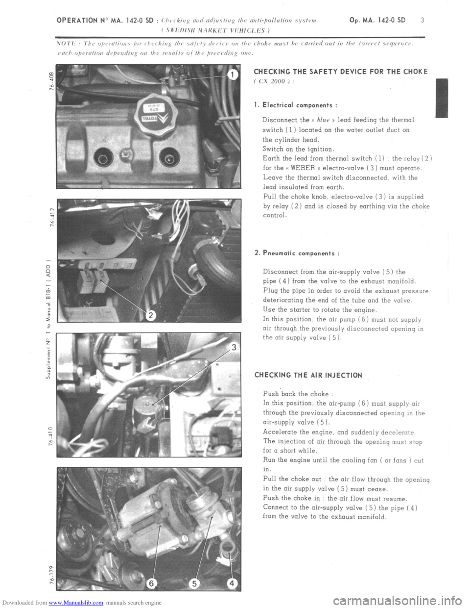
1. Electrical components :
Disconnect the u blur )) lead feeding the thermal
switch (1) located on the water outlet duct on
the cylinder head.
Switch on the ignition.
Earth the lead from thermal switch ( 1) the relay ( 2 )
for the << WEBER 1) electro-valve ( 3) must operate.
Leave the thermal switch disconnected with the
lead insulated from earth.
Pull the
choke knob. electro-valve (3) is supplied
by relay (2 ) and is closed by earthing via the choke
control.
2. Pneumatic components :
Disconnect from the air-supply valve ( 5) the
pipe (4) from the valve to the exhaust manifold.
Plug the pipe in order to avoid the exhaust pressure
deteriorating the end of the tube and the valve
Use the starter to rotate the engine.
In this position. the air pump (6 j must
not supply
air through the previously disconnected opening in
the air supply valve ( 5)
CHECKING THE AIR INJECTION
Push back the choke
In this position. the air-pump (6 ) must supply air
through the previously disconnected opening in the
air-supply valve ( 5 1.
Accelerate the engine, and suddenly decelerate
The injection of air throuqh the opening must stop
for a short while.
Run the engine until the cooling fan ( or fans ) cut
in.
Pull the choke out : the air flow through the opening
in the air supply valve ( 5) must cease.
Push the choke in : the air flow must resume.
Connect to the air-supply valve ( 5) the pipe ( 4 )
from the valve to the exhaust manifold.
Page 116 of 394
Downloaded from www.Manualslib.com manuals search engine Op. MA.IE. 144-O 1 I - PRECAUTIONS TO BE TAKEN WHEN WORKII;(G ON A VEHICLE FITTED WITH THE (t L-JETRONIC n
SYSTEM.
1.
Do not run the engine if the battery leads are improperly secured
2. Do not use a quick-start charging trolley for starting the engine
3. Never disconnect the battery with the engine running
4. When charging the battery, disconnect the leads
5. Before checking the injection system, check the ignition : (advance, advance curve, proper grade of plugs 1
6. Remove the E C U before putting the vehicle through a paint-stoving oven
7. Check the conditions of the various connections
8. Never disconnect the E,C U. while the ignition is on
9. When checking compression, disconnect the positive terminal of the coil (in order to stop the injection signal). 10.
When carrying out a check requiring an ohmmeter, use exclusively a battery-powered ohmmeter. II. FAULT-FINDING.
1. THE ENGINE DOES NOT START, OR IS DIFFICULT TO START . . . . . . . . . . . . . . . . . . . . . . . . . . . . . . . . . . . . . . . . . . . . . . . . . . . . . . . . P. 2
2. THE ENGINE STARTS, THEN STOPS . . . . . . . . . . . . . . . . . . . . . . . . . . . . . . . . . . . . . . . . . . . . . . . . . . . . . . . . . . . . . . . . . . . . . . . . . . . . . . . . . . . . . . . . . . . . . . . . . . . . . . P. 3
3. UNSTABLE OR INCORRECT IDLING SPEED, EXCESSIVE FUEL CONSUMPTION ........................ P:5
-4. ENGINE MISFIRES AT .ALL SPEEDS ........................................................................................................
P. 7
5. LACK OF POWER . . . . . . . . . . . . . . . . . . . . . . . . . . . . . . . . . . . . . . . . . . . . . . . . . . . . . . . . . . . . . . . . . . . . . . . . . . . . . . . . . . . . . . . . . . . . . . . . . . . . . . . . . . . . . . . . . . . . . . . . ................ P. 9
Page 119 of 394

Downloaded from www.Manualslib.com manuals search engine OPERATION N” MA.IE. 144-0 : (.I I(“ i//g N//f/ nrl;clslir,g Ill<’ 0 I.-j<~/ro/,ic 1)
/I/(,/ illj(‘c-lior, sy.~lvm.
I
2-
?HE ENGINE STARTS, THEN STOPS
Page 148 of 394

Downloaded from www.Manualslib.com manuals search engine ANNEXE : C CHECKING THE FUEL CIRCUIT AND PRESSURE
- Remove the cold-start injector ( 1) and carefully
remove its petrol feed pipe.
- Connect pressure gauge ( 2) onto the cold-start
injector petrol line.
- Fit the cold-start injector zmto the manifold.
- Run the engine at idling speed the petrol pressure
must be regulated to 2 bars ( 29 psi ).
- Disconnect the vticuum pipe ( 3 i from the pressure
regulator the regulated pressure must be 2.5 bars
i 36 l/4 psi ).
If one of the readings is incorrect, check condition
of the flexible vacuum pipe for the pressure
regulator. as well as its aspect. If it is satisfactory
replace the pressure requlotor after making sure
that its VCICUU~ pipe is not blocked totally or
partially at the manifold end.
With the engine stopped, the pressure must
remain stable at 2 bars ( 23 psi ); if not, check
for a leak which could be found at the cold-start
injector, one of the main injectors. or at the level
of the pressure regulator valve diaphragm.
Page 151 of 394
Downloaded from www.Manualslib.com manuals search engine 2 OPERATION No MA. 173.0 : C/ l<,C ,,,g //JP p/r”/ SuppI) k’
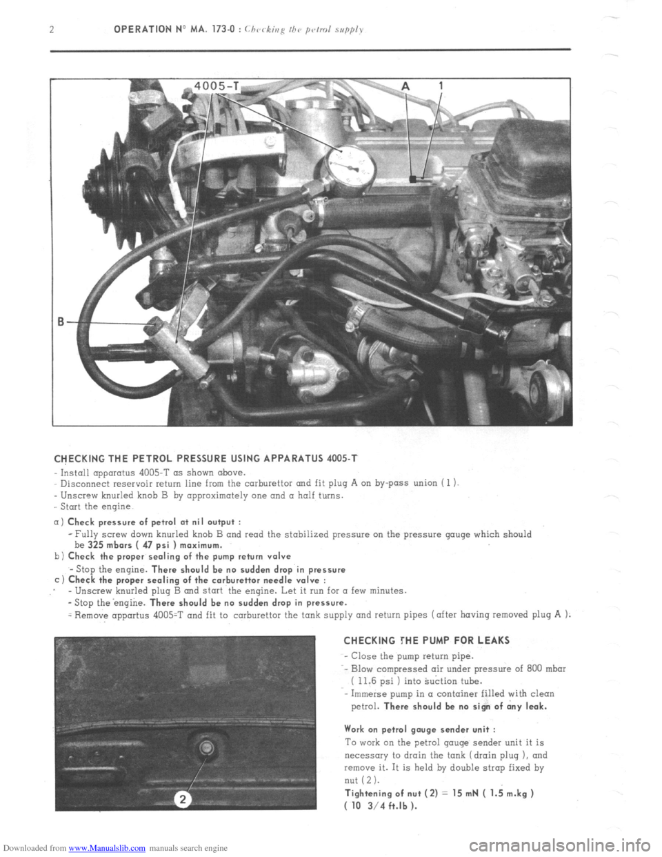
CHECKING THE PETROL PRESSURE USING APPARATUS 4005-T
Install apparatus 4005-T as shown above.
Disconnect reservoir return line from the carburettor and fit plug A on by-pass union ( 1 1.
Unscrew knurled knob B by approximately one and a half turns.
Start the engine
a) Check pressure of petrol at nil output :
b
c -Fully screw down knurled knob B and read the stabilized pressure on the pressure gouge which should
be 325
mbors ( 47 psi ) maximum.
Check the proper sealing of the pump return valve
-Stop the engine. There should be no sudden drop in pressure
Check the proper sealing of the carburettor needle valve :
- Unscrew knurled plug B and start the engine. Let it run for a few minutes.
-Stop theengine.
There should be no sudden drop in pressure.
= Remove apportus 4005=T and fit to carburettor the tank supply and return pipes (after having removed plug A 1:
CHECKING THE PUMP FOR LEAKS
- Close the pump return pipe.
-- Blow compressed air under pressure of 800 mbar
( 11.6 psi ) into Suction tube.
Immerse pump in a container filled with clean
petrol.
There should be no sign of dny leak.
Work on petrol gauge sender unit :
To work on the petrol gouge sender unit it is
necessary to drain the tank (drain plug 1, and
~emcwe it. It is held by double strap fixed by
nut (2 1.
Tightening of nut (2) = 15 mN ( 1.; m.kg )
( 10 3/4 ft.lb ).
Page 228 of 394
Downloaded from www.Manualslib.com manuals search engine 2 OPERATION No MA. 390-O : Checking the hydra&c conponmts on the.uehicle
f Mnnual sirrrin~ uehicles J CHECKS
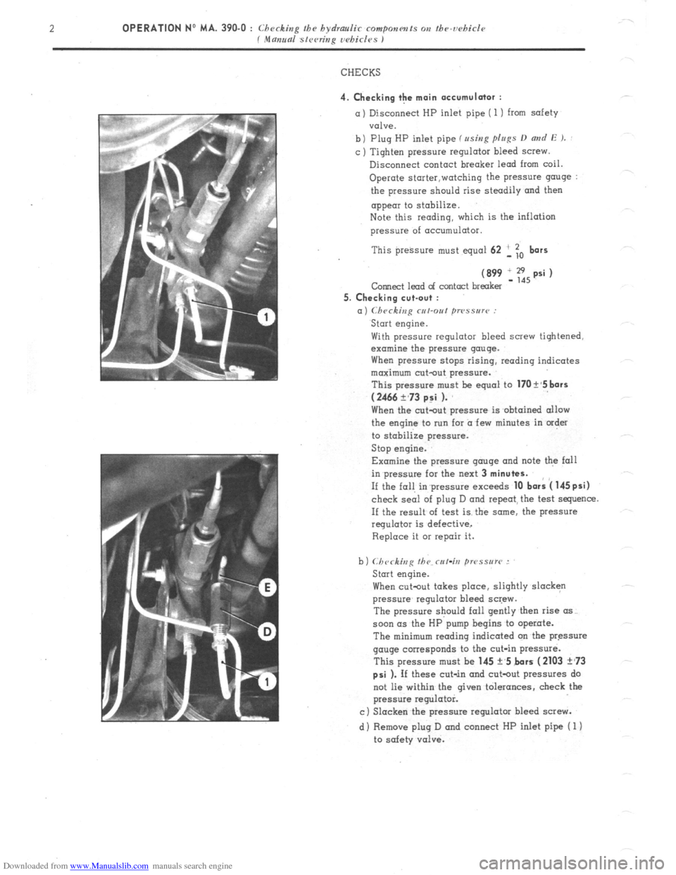
4. Checking the main accumulator : a) Disconnect HP inlet pipe ( 1) from safety
valve.
b) Plug HP inlet pipe fusing p[u~s D
and E ). : c ) Tighten pressure regulator bleed screw.
Disconnect contact breaker lead from coil.
Operate storter,watching the pressure g”“ge :
the pressure should rise steadily and then
appear to stobilize.
Note this reading, which is the inflation
pressure of acc”mulator.
This preksure must equal 62 ‘, To
bars
(899 IE,psi) Corned lead of contact breaker
5. Checking cut-out :
a) Checking cut-out ~TPSSU~~~ : Start engine.
With pressure regulator bleed screw tightened,
examine the pressure gauge.
When pressure stops rising, reading indicates
maximum cut-out pressure.
This pressure m”st be equal to
170 t’5 bars
(2466 ?,73 p:i ). When the c”t-o”t pressure is obtained allow
the engine to nrn for a few minutes in order
to stabilize pressure.
Stop engine.
Examine the pressure gauge and note the fall
in pressure for the next 3
minutes. If the fall in’pressure exceeds
10 bark 4 145psi) check seai of plug D and repeat, the test sequence.
If the result of test is the some, the pressure
regulator is defective,
Replace it 01 repair it.
When cutout takes place, slightly slacken
pressure regulator bleed screw.
The pressure should fall gently then rise (IS~.
soon (IS the HP pump begins to operate.
The minimum reading indicated on tbe pressure
gauge corresponds to the cut-in pressure.
This pressure must be 145 +,5 bars
(2103 ?,73
psi ). If these cut-in and cot-out pressures do
not lie within the given tolerances, check the
pressure regulator.
c) Slacken the pressure regulator bleed screw.
d) Remove plug D and connect HP inlet pipe ( 1)
to safety valve.
Page 229 of 394
Downloaded from www.Manualslib.com manuals search engine OPERATION No MA. 390-O : Checkin
P the hydraulic componm~s on the ucbicle Op. MA. 390-O 3
f Mama sleeting wbi&s I
6. Checking the safety valve :
=I
bl
Cl
dl
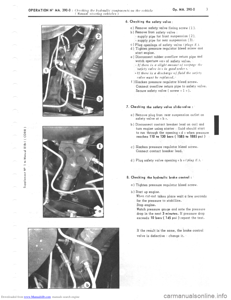
Remove safety v&e fixing screw ( 1 ).
Remove from safety valve :
supply pipe for front suspension (2 ),
- supply pipe for rem suspension (3):
Plug openings of safety valve ( pIugs E J.
Tighten pressure regulator bleed screw
and
start engine.
Disconnect rubher overflow return pipe and
watch aperture ~a>> of safety valve.
- I/ Iherr is a slight c7moa,,t 0, sHymge thr
sa/cty ~dve is s in good ordrv n.
el
-If thrr~ is a discharge of fluid the sniw
dw must be rqlacrd..
f ) Slacken pressure regulator bleed screw-
Conned overflow return pipe to safety valve.
Secure safety valve ( screw (( 1 a) 1.
7. Checking the safety valve slidevolve :
a) Remove plug from rem suspension outlet on
safety v&e at G b >a.
b ) Disconnect contact breaker lead on coil and
turn engine using stmter : fluid should start
to run through the opening a d N when pressure
reaches
1lLl +o 130 bars ( 1585 to 1885 psi )
c) Slacken pressure regulator bleed screw.
Connect contact breaker lead.
d ) Plug safety valve opening u b )) (plug E ).
8. Checking the hydraulic brake contml :
m ) Tighten pressure regulator bleed screw.
b) Start up engine.
When cut-out takes place wait a fen: seconds
for the pressure to stobilize.
Stop engine%
Watch pressure gauge and note the pressure
drop in the next 3
minutes. If pressure drop
exceeds 10 bors*( 145 psi ) repeat the test.
If the re< is the same. the broke control
valve is defective : change it.
Page 230 of 394
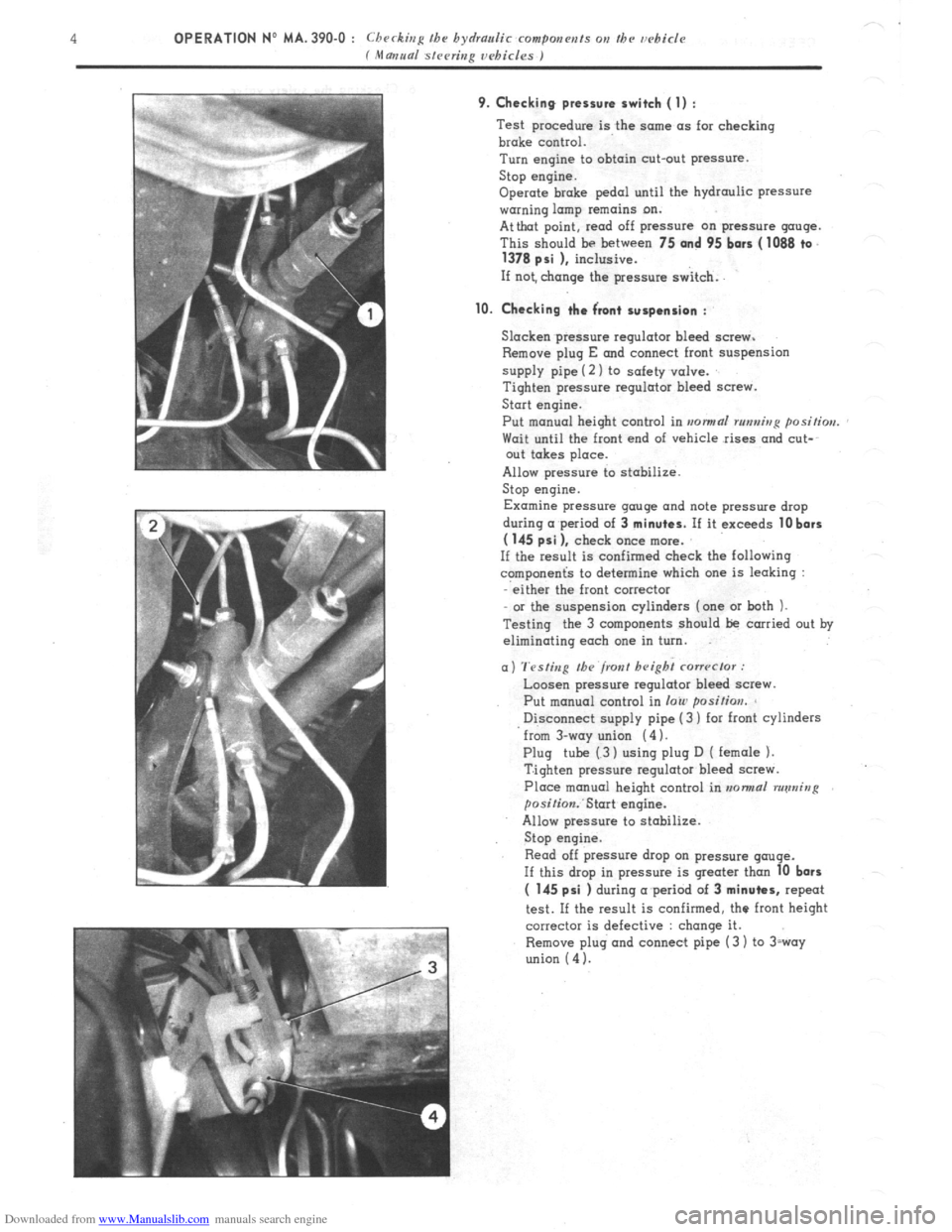
Downloaded from www.Manualslib.com manuals search engine 9. Checking pressure switch (1) : Test procedure is the sctme as for checking
broke control.
Turn engine to obtain cut-out pressure.
Stop engine.
Operate brake pedal until the hydraulic pressure
warning lamp remains on.
Attbat point, read off pressure on pressure gauge.
This should be between 75
and 95 bars ( 1088 ta.
1378 psi 1, inclusive.
If not, change the pressure switch.
10. Checking the Front suspension : Slacken.pressure regulator bleed screw.
Remove plug E and connect front suspension
supply pipe (2 ) to safety valve.
Tighten pressure regulator bleed screw.
Start engine.
Put manual height control in
rronnaf rtmni>rp positim. Wait until the front end of vehicle rises and cut-
out takes place.
Allow pressure to stabilize.
Stop engine.
Examine pressure gauge and note pressure drop
during wperiod of 3
minutes. If it exceeds 10 bars
( 145 psi 1, check once more.
If the result is confirmed check the following
c?mponenG to determine which one is leaking :
either the front corrector
or the suspension cylinders (one or both ).
Testing the 3 components should be carried out by
eliminating each one in turn.
(I) Testing the front height cmwclor : Loosen pressure regulator bleed saew.
Put manual control in
loin position. Disconnect supply pipe (3 ) for front cylinders
from 3-way union (4 ).
Plug tube (3 ) using plug D ( female 1.
Tighten pressure regulator bleed scwe.
Place manual height control in normal running
posiGon:Start engine.
Allow pressure to stabilize.
Stop engine.
Read off pressure drop on pressure qtruqe.
If this drop in pressure is greater than
10 bars (
145 psi ) during a period of 3 minutes, repeat
test. If the result is confirmed, the front height
corrector is defective : change it.
Remove plug and connect pipe (3 ) to 3roy
union
(4 ).
Page 283 of 394
Downloaded from www.Manualslib.com manuals search engine Op. MA. 453-O 1
I. BLEEDING THE BRAKES ON SALOON AND ESTATE VEHICLES ( 9/1976- )
A. FRONT BRAKE BLEEDING
NOTE : To avoid emulsifying the fluid
and the
consequent formation of air-pocket in the system,
the circuit should not be under pressure when this
operation is carried out.
1. Release pressure in circuits :
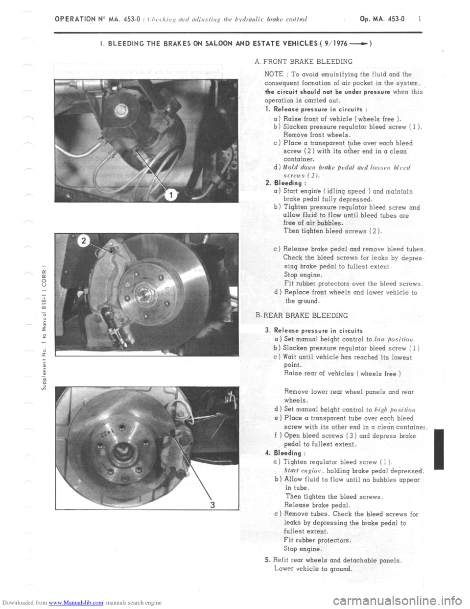
a) Raise front of vehicle (wheels free 1.
b) Slacken pressure regulator bleed screw ( 1 ).
Remove front wheels.
c ) Place CI transparent tube over each bleed
screw (2 ) with its oiher end in CI clean
container.
d) Hold r/on,,,
brake pdnl ar,d loose,, blvcrl
*cr(Iws (2). 2. Bleeding :
(I 1 Start engin’e (idling speed 1 and maintain brake
pedal fully depressed.
b) Tighten pressure regulator bleed screw and
allow fluid to flow until bleed tubes ore
free of air bubbles.
Then tighten bleed screws (2 ).
c) Release broke pedal and remove bleed tubes.
Check the bleed screws for .leaks by depres-
sing brake pedal to fullest extent.
Stop engine.
Fit rubber protectors over the bleed screws.
d 1 Replace front wheels and lower vehicle to
the ground.
B. REAR BRAKE BLEEDING
3. Release pressure in circuits
a) Set monuol height control to lou posi/iou.
b 1 Slacken pressure regulator bleed screw ( 1 )
c) Wait until vehicle has reoched.its lowest
point.
Raise rear of vehicles (wheels free )
Remove lower rear wheel panels and rear
wheels.
d 1 Set manual height control to
hifih positior,
e ) Place Q transparent tube over each bleed
screw with its other end in (I cl&n container.
f ) Open bleed screws (3 ) and depress broke
pedal to fullest extent. 4. Bleeding :
(I) Tighten regulator bleed screw ( 1 1.
Slur/ w?@nr, holding broke pedal depressed.
b) Allow fluid to flow until no bubbles appear
in tube.
Then tighten the bleed screws.
Release brake pedal.
c ) Remove tubes. Check the bleed screws for
leaks by depressing the bloke pedal to
fullest extent. I
Fit rubber protectors.
Stop engine.
5. Refit rear wheels and detachable panels.
Lower vehicle to ground.