starter Citroen CX 1985 1.G Owner's Manual
[x] Cancel search | Manufacturer: CITROEN, Model Year: 1985, Model line: CX, Model: Citroen CX 1985 1.GPages: 394
Page 352 of 394

Downloaded from www.Manualslib.com manuals search engine 1 ALL ENGINES
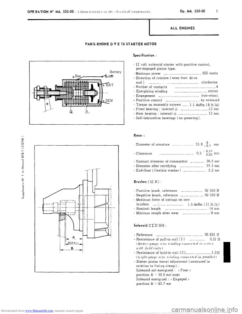
PARIS-RHONE D 9 E 16 STARTER MOTOR
Battery Specification :
- 12 volt solenoid starter with positive control,
pre-engaged pinion type.
- Maximum power ,..... ,................................. 920 watts
- Direction of rotation ( seen from drive
end ) ., . . . ._..,.,...,.,..................... clockwise
- Number of contacts __..... . . . . . . . . . . . . . . . . . . . . . . . . . . . 4
- Energizing winding . . . . . . . . . . . . . . . . . . . . . . . . . . . . . . . . . . series
- Enqagement ,“...,.,.........,.,.............,......... free-wheel
- Positive control ._.,.,.,.,.,.,.......,.,.,....... . by solenoid
- Torque on assembly screws . . . . . . 1.1 daNm (8 ft.lb)
- Front bearing : internal 4 ,..._.,.....,...,.,.,. _....._. 12 mm
- Rear bearing : internal $I ._...,...,...,.,.,.,. ,.....,. 12 mm
- Self-lubrication bearings ( no greasing ). Rotor :
Diameter of armature . . . . . . . . . . . . . . . 55.9 - ;.I mm
- Clearance _.......................... . . . . . . 0.5 ’
0.17
0.05 mm
- “Jominal diameter of commutator . . . . . . . . . . . . . . . . 36.5 mm
- Diameter after rectifying ,.....,................... 35.5mm
- End-float (flexible washer) ,....._.,... . . . 2.2 mm Brushes (52
R) :
- Positive brush, reference . . . . . . . . . . . . . . 92 550 N
- Negative brush, reference ,...,.,.,.,.,. ,.,.,. . . . 92 550 N
- Maximum force of springs on new
brushes ,... ..I. . ,. ,. . . . ..,......... 1.5 daNm (11 ft.lb)
- Nominal length
,... . . . . . . .., . . . . . . . .,......... 14 mm
- Minimum length after wear . . . . . . . ..,......... 8 mm Solenoid
CED 509 :
- R.eference . . . . . . . . . . . . . . . . . . . . . . . . . . . . . . . . . . . . . . . ,.,. 95 631 U
- Resistance of pull-in coil (1 ) . . . . . 0.21 Q
(Heaz’y-gauge wire IL’i?/dirzg cotlucctcd iu .sc,ricJs
with field coils )
- Resistance of hold-in coil ( 2 ) . . . . . . . . . . . . . . . . . . . . . . . . . . 1.3 Q
( Light-gc7zigc wire’ 11 itlrliug conwctcrl in pdrallrl )
- Starter pinion travel adjustment (measured in
relation to fixi ng clamp ) :
Solenoid not energized : (( Free ))
position A = 30.5 mm maxi
Solenoid energized : (( Engaged 1)
position B = 43.7 mm
Page 355 of 394

Downloaded from www.Manualslib.com manuals search engine m- 6 7 3. Checking operation of starter pinion (4) in
/ forward position :
7hcrc “lP ,,c,, nllrn,nli,~r~ rn<~~h”LS : OPERATION No MA. 530-O : (./ 1< ‘ ,,,g II,‘, vl<~rtricnl rompo,,w,ls , -k’ Op. MA. 530-O 3
ALL ENGINES
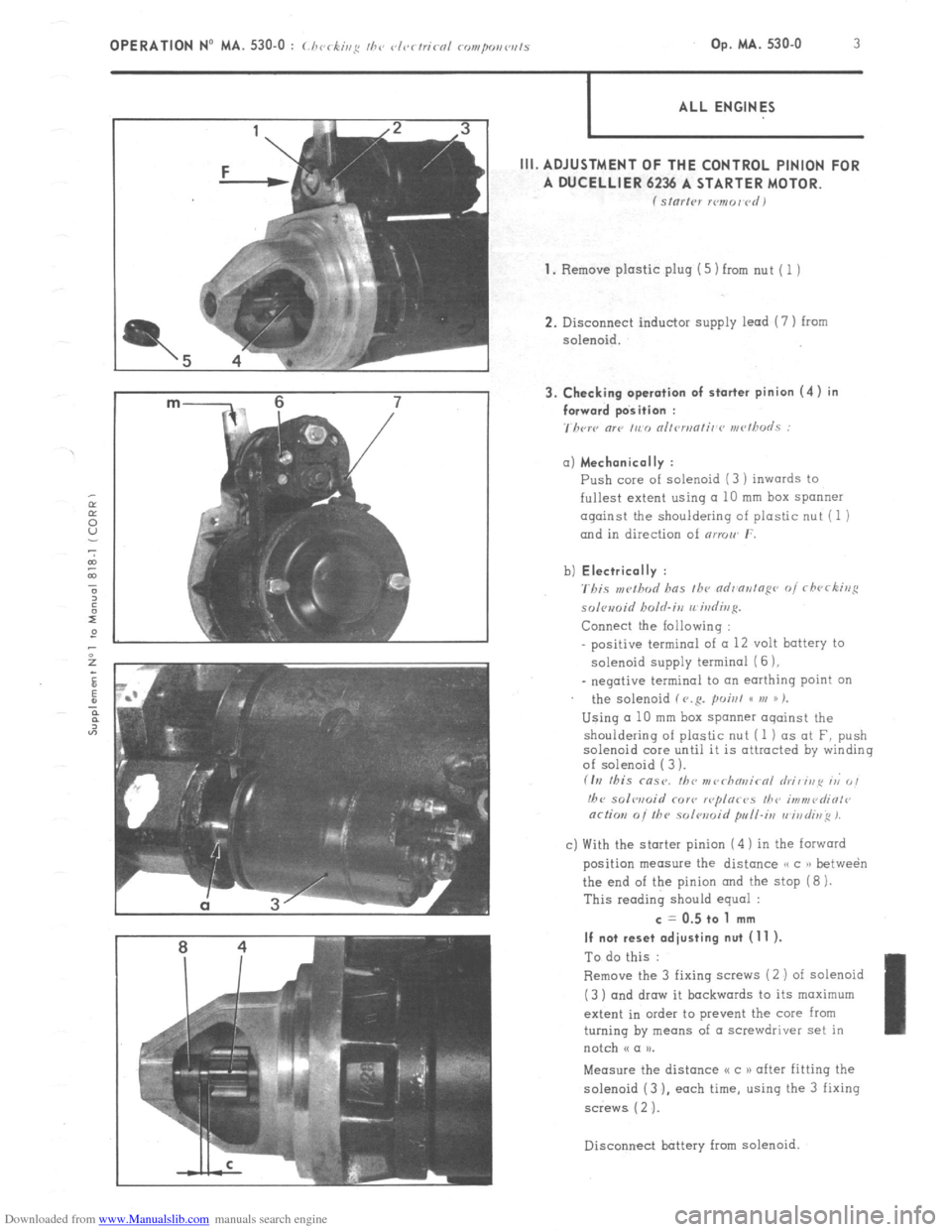
III. ADJUSTMENT OF THE CONTROL PINION FOR
A DUCELLIER 6236 A STARTER MOTOR.
f Sl”l’,Pl xmor~rdI
1.
Remove plastic plug (5) from nut ( 1 )
2. Disconnect inductor supply lead (7 ) from
solenoid. a) Mechanically :
Push core of solenoid (3 ) inwards to
fullest extent using a 10 mm box spanner
against the shouldering of plastic nut (1 )
and in direction of nrmw r.
b) Electrically :
'rbis ,w!hod has fh~ ndr'ontopr~ of rfwrking
solomid holrl.irz rrirdivg.
Connect the Iollowing :
positive terminal of (I 12 volt battery to
solenoid supply termina1 (6 ),
_ negative terminal to an earthing point on
the solenoid f V.R. poisl GC VI )) %
Using a 10 mm box spanner oqainst the
shouldering of plastic nut (1 ) as at F, push
solenoid core until it is attracted by winding
of solenoid ( 3 ).
fIrI this msr. fbc nr~~rhn~~irnl hi, irip ri 0,
!hc solwoid COY<, r<~plor<~s I/?<, i,,?“,<~diOl<~
or/ion 0i the solwoid pull-i,, vi,,di~~ 1.
c) With the starter pinion (4 ) in the forward
position measure the distance /, c )r betwe&
the end of the pinion and the stop (8 ).
This reading should equal : c = 0.5 to 1 mm
If not reset adjusting nut (11 ).
To do this :
Remove the 3 fixing saews (2 ) of solenoid
(3 ) and draw it backwards to its maximum
extent in order to prevent the core from
turning by means of a screwdriver set in
notch N a u.
Measure the distance I< c 1) after fitting the
solenoid (3 ). each time, using the 3 fixing
screws ( 2 ‘J.
Disconnect battery
from solenoid.
Page 356 of 394

Downloaded from www.Manualslib.com manuals search engine 4 OPERATION No MA. 530-O : Cbrckivp thr elrrfriral romponrwts 4. Checking starter pinion (4) in the free position :
With
the solenoid (3 ) mounted on starter, the
starter pinion (4 ) is normaHy in free position
Measure the distance o d n between the flange
of the starter nose at u b H in the bore
of the
motor housing and the extremity of the starter
pinion.
This reading should
equal :
d = 30.5 mm maxi
If not, recondition the starter.
Connect the inductor supply wire (I I
Refit plastic plug (5.1 (see page 3 1.
Page 357 of 394

Downloaded from www.Manualslib.com manuals search engine OPERATION No MA. 530.0 : Chcrking the vlr,rtricol components Op. MA. 530.0 5
I ALL ENGINES
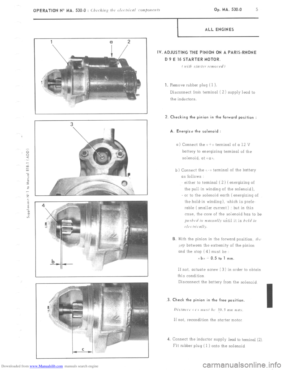
IV. ADJUSTING THE PINION ON A PARIS-RHONE
D 9 E 16 STARTER MOTOR.
i wirh s,orfw lcmo~ <‘d)
1.
Remove rubber pluq (1 1.
Disconnect from terminal ( 2 ) supply lead to
the inductors. 2. Checking the pinion in the forward position :
A. Energize the solenoid :
a ) Connect the u + >a terminal of a 12 V
battery to energizing terminal of the
solenoid, at NCIU.
b) Connect the GS -B) terminal of the battery
as ‘follows :
either to terminal (2) ( enerqizinq of
the pull-in winding of the solenoid),
OI to the solenoid earth ( enerqizing of
the hold-in winding ), which is prefe-
rable (smaller current) : but in this
case, the core of the solenoid has to be
pr~41crl iu mmanll~ uritil it is held iu
P/C< hi< nllv.
6. With the pinion in the forward position, I/Z<,
cop between the extremity of the pinion
and the stop ( 4) must be : s< bn 0.5 to 1 mm.
If not, actuate screw ( 3 1 in order to obtain
this condition
Disconnect the battery kxn the solenoid.
4. Connect the inductor supply lead to terminal (2)
Fit rubber plug ( 1 j onto the solenoid