ESP CITROEN CX 1988 Service Manual
[x] Cancel search | Manufacturer: CITROEN, Model Year: 1988, Model line: CX, Model: CITROEN CX 1988Pages: 648, PDF Size: 95.8 MB
Page 3 of 648
The special tool nurnbers and photos appear in the operation description as the work progresses.
The tools referenced OUT followed by 6
figures and ending in the letter “T” are sold by the Replacement
Parts Department to FRANCE and EXPORT networks.
The tools referenced with 4
figures followed by the letter “T” are sold to FRANCE by the Societe FENWICK,
Departement AMA :
24, boulevard Biron, 93404 SAINT-OUEN. Tel. : 42.52.67.00, and to the EXPORT network by CITROEN.
The tools referenced MR must be made up by the repairer himself TOOLS
For each chapter, the photos
end of the list of operations. of the special
tools required for proper complei :ion of the work, are given at the
TIGHTENING TORQUES:
The tightening torques are expressed in metre Decanewton (mdaN), the official torque measuring unit:
0.981 mdaN = 1 mkg (former measuring unit).
In practice, 1 mdaN = 1 mkg.
UPDATING THE MANUAL WITH ADDITIVES:
Additives should be ordered immediately on receipt of the DOCUMENTATION BULLETIN announcing that
they are issued.
The updated sheets must be added to the existing pages in the manual or replace the corresponding ones. They
are identified by spots located to the left of the shortened volume number placed at the bottom right hand side
of the recta page:
Example : 1 spot
l 8531 additive no. 1 ; 2 spots l * 8531 additive no. 2, etc.
IMPORTANT NOTE:
For all technical information, please apply to:
CENTRE TECHNIQUE CITROEN
Division Apres-Vente
Service Technique
Chemin Vicinal no 2 - 78140 VELIZY
TBI. : 45.37.30.30.
1) ;'.
. .
. .::, _ “*:jy%.
-;'1*,,
':; . .
Page 25 of 648
1
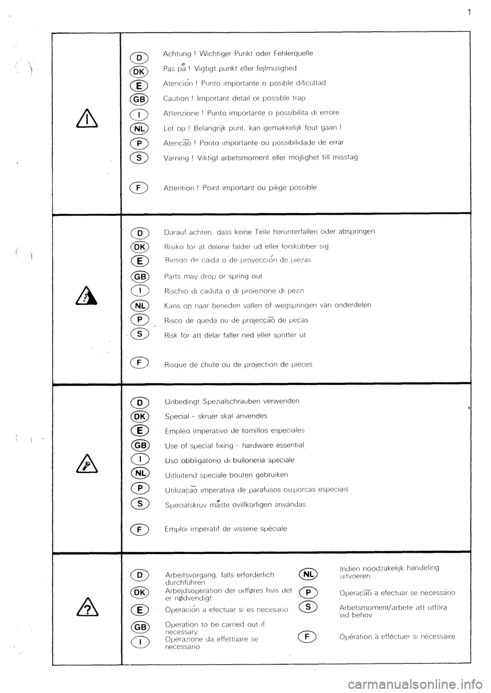
Achtung ! Wrchtiger Punkt oder Fehlerquelle
Pas p: ! Vrgtrgt punkt eller fejlmrtlrghetf
Atenci& ! Ptrnto rrnportante o posrble drfrcuitad
Cautron ! Important detarl or possible trap
Attenrione ! Punto rmportante o possrbrlrta tli errore
Let op ! Belangrijk punt, kan gemakkelrlk fout gaan !
Atenc% ! Ponto rmportante ou possrbilrdade de errar
Varning ! Vrktigt arbetsmoment eller mojlrghet till misstag
Attention ! Point important ou piege possible
Darauf achten. dass ketne Teile herunterfallen oder abspnngen
Rrsrko for at delene falder ud eller forskubber srg
Resqo de carda o de proyccc~& de j,reras
Parts may drop or spring OlJl
Rrschro d caduta o di proierione cl1 pezzr
Kans op rraar beneden vallen of Wegs[Jrlrqen van onderdelen
R~sco de queda ou de project% de pecas
Risk for att delar failer ned eller sprrtter ut
Rtsque de chute ou de projection de yreces
Unbedrngt Spezralschrauben verwenden
Specral - skruer skal anvendes
Emyleo tmperativo de tornillos especlales
Use of special fixing - hardware essenttal
Uso obblrgatono di bulloneria specrale
Urtlurtend specrale bouten gebruiken
UtrlizacG rrnperativa de parafusos ou yorcas especiars
Specralskruv mzste ovrllkorlrgen anvandas
Emplor tmperatrf de vtssene spectale
uttvoeren
Opera@6 a efectuar se necessdrio
Arbetsmoment/arbete att utfora
Operation to be carned out tf
Operatron a effectuer st necessarre
Page 29 of 648
5
B
e0
.
we? ,--
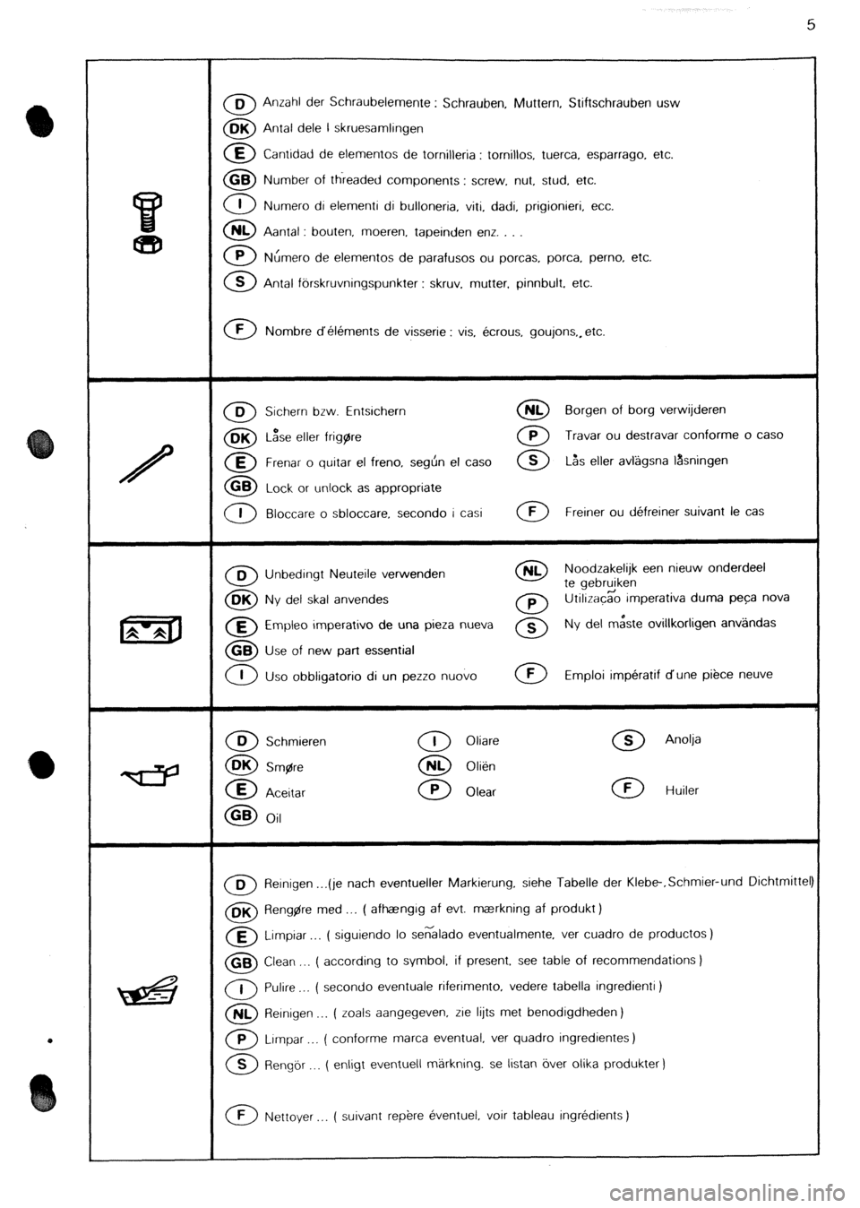
0 0 Anzahl der Schraubelemente : Schrauben, Muttern, Stiftschrauben usw
0 BK Antal dele l skruesamlingen
0 E Cantidad de elementos de tornijleria : tomillos, tuerca. esparrago, etc.
0 GB Number of threaded components : screw, nut, stud, etc.
0 1 Numero di elementi di bulloneria, viti, dadi, prigionieri, etc.
0 NL Aantal : bouten, moeren. tapeinden enz. . .
0 P Nhmero de elementos de parafusos ou porcas, porca, perno, etc.
0 B Antal fbrskruvningspunkter : skruv. mutter, pinnbult. etc.
0 F Nombre d’elements de visserie : vis, ecrous, goujons,, etc.
0 D Sichern bzw. Entsichern 0 NL Borgen of borg verwijderen
0 BK L&e eller frigare 0 P Travar ou destravar conforme o case
0 E Frenar o quitar el freno, seghn el case 0 S L&s eller avlagsna lasningen
0 GB Lock or unlock as appropriate
0 I Bloccare o sbloccare, second0 i casi 0 F Freiner ou defreiner suivant le cas
0 B Unbedingt Neuteile verwenden 0 NL Noodzakelijk een nieuw onderdeel
0
te gebruiken OK
Ny del skal anvendes 0 P Utilizacgo imperativa duma peca nova
0 E Empleo imperativo de una pieza nueva 0 s Ny del m&te ovillkorligen anv;ilndas
0 GB Use of new part essential
0 I
Uso obbligatorio di un pezzo nuovo 0 F Emploi imperatif dune piece neuve
0 D Schmieren
0 OK Smgre
0 E
Aceitar
0 GB Oil
0 I Oliare
0 NL Olien
0 P Olear
0 S Anolja
0 F Huiler
m Reinigen . ..(je nach eventueller Markierung. siehe Tabelle der Klebe-.Schmier-und Dichtmittel
0 BK Aeng$re med ,.. ( afhaangrg af evt. maerkning af produkt )
a Limpiar ( siguiendo lo se6lado eventualmente, ver cuadro de productos)
0 GB Clean ,.. ( according to symbol. if present, see table of recommendations )
0 I Pulire . . . ( second0 eventuale riferimento, vedere tabella ingredienti )
0 NL Reinigen _.. ( zoals aangegeven, rie lijts met benodigdheden)
0 P Lrmpar . ( conforme marca eventual, ver quadro ingredientes)
0 S Rengor __. ( enligt eventuell markning. se listan over olika produkter )
0 F Nettoyer ( suivant rep&e eventuel, voir tableau ingredients )
Page 31 of 648
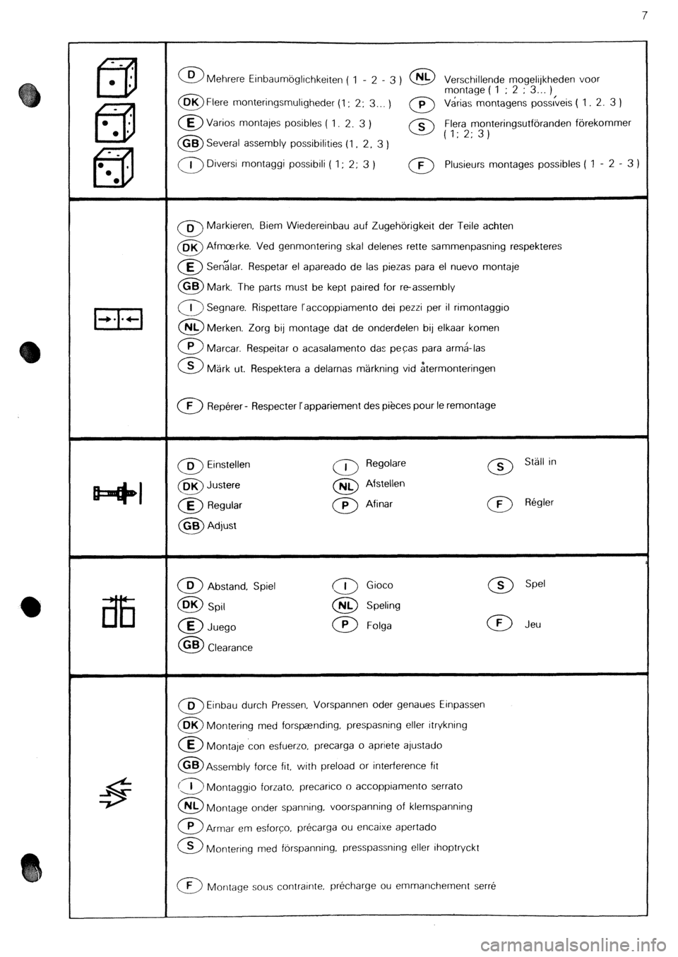
0 D Mehrere Einbaumoglichkeiten 1 -
( 2 - 3 ) 0 NL Verschillende voor mogelijkheden
0 OK 1 ; 2 ; 3...
Flere monteringsmuligheder (1: 2;
3... )
0 p Varias montage montagens ( pos&eis ) ( 1 2. 3 1
0 E Varios montajes posibles ( 1. 2. 3
)
0 0
Flera monteringsutforanden forekommer
GB Several assembly possibilities (1, 2, 3 ) ’ (1:2;3)
0 1 Diversi montaggi possibili ( 1 ; 2; 3 ) 0 F Plusieurs montages possibles ( 1 - 2 - 3 1
0 B Markieren, Biem Wiedereinbau auf Zugehorigkeit der Teile achten
0 BK Afmcerke. Ved genmontering skal delenes rette sammenpasning respekteres
0 E Senzlar. Respetar el apareado de las piezas para el nuevo montaje
0 GB Mark. The parts must be kept paired for reassembly
0 I Segnare. Rispettare l’accoppiamento dei pezzi per il rimontaggio
0 NL Merken. Zorg bij montage dat de onderdelen bij elkaar komen
a Marcar. Respeitar o acasalamento das pecas para arm&las
0 S Mark ut. Respektera a delarnas markning vid itermonteringen
0 F Reperer - Respecter I’appariement des pieces pour le remontage
0 B Einstellen 0 I Regolare 0 S Stall in
0 BK Justere 0 NL Afstellen
0 E Regular 0 P Afinar 0 F Regler
0 GB Adjust
0 D Abstand, Spiel
0 DK Spil
0 E Juego
0 GB Clearance
0 I Gioco
0 NL Speling
0 P Folga
0 S Spel
0 F Jeu
0 D Einbau durch Pressen, Vorspannen oder genaues Einpassen
0 DK Montering med forspaending, prespasning eller itrykning
@ Montaje con esfuerzo. precarga o apriete ajustado
0 GB Assembly force fit, with preload or interference fit
(3 Montaggio forrato, precarico o accoppiamento serrato
0 NL Montage onder spanning, voorspanning of klemspanning
0 P Armar em esforco, precarga ou encaixe apertado
0 S Montering med f&spanning. presspassning eller ihoptryckt
0 F Montage sous contrainte. precharge ou emmanchement serre
Page 212 of 648
CHECKING AND ADJUSTING
THE INJECTION SYSTEM
II. - INSPECTION AND TIMING OF THE “ROT0-DIESEL” INJECTION PUMP
Raise the LH side of the vehicle and support it on
stands.
Disconnect the battery negative lead.
Engage the 5th gear. Rotate the engine by turning the
wheel.
Set the No. 1 cylinder to the initial timing point,
Fig.1.
(look into the oil filter orifice).
- place cylinder No. 1 valves in the rocking position;
turn the crankshaft by one turn in the normal direc-
tion of engine rotation.
- align marks on the flywheel and on the crankcase
(++I.
- turn the crankshaft back through a quarter of a turn.
Remove either the plug (with a 32 mm ring spanner)
or the inspection plate depending on the type of the
pump.
Refit, Fig II or Ill, according to pump:
- the feeler,
- the support for the dial-gauge.
- the dial-gauge equipped with its right-angled lever.
Finding the pump internal timing point:
- turn the crankshaft in the direction of rotation until
the large pointer on the dial indicator starts moving
in the opposite direction.
- set “0” mark on the dial-gauge in line with the large
pointer.
Checking the injection pump timing:
- rotate the crankshaft by a quarter turn in the oppo-
site direction to its direction of rotation.
- turn back in the normal direction of rotation until the
“0” mark on the dial-gauge has been reached.
- in that position, marks (-1 and (c) should be in line,
Fig. I.
If not, re-check the timing. Timing the injection pump:
- set the engine to the initial trming point, Fig. I.
- turn the crankshaft by 114 turn in the opposite direc-
tion to normal direction of ro’tatron, then turn back
in the direction of rotation to bring marks t-+) and
+-I opposite.
Adjusting the pump timing, Fig. Ill:
Slacken off the injector pipe connections and the 4
attachment points.
Bring the pump to the injection point with the feeler
at the base of V-shaped groove (timing point).
Set the “0” mark on the dial opposite the needle on
the dial-gauge. Orientate the pump casing towards the
engine.
Slowly turn back to the injection point (needle facing
the “0” mark on the dial), by moving the pump
casing away from the engine (in the opposite direc-
tion to engine rotation).
Tighten the pump fixing nuts to 2.4 mdaN. During
this operation, the needle should not move.
Check the pump timing
Remove the timing tools.
Refit the plug, (tighten to 2 mdaN), or the inspec-
tion plate.
Seal the injection pump plug.
Tighten the injector pipe connections to 2 mdaN.
Reconnect the battery negative cable
Switch on the ignition (electrical STOP solenoid exci-
tation) and prime the fuel circuit using the manual
pump (5) located on the filter.
Fully depress the accelerator pedal to facilitate the
engine bleeding and start.
Note: the initial timing point corresponds to:
3.24 -L- 0.05 mm BTDC: M 25/648
4.32 + 0.05 mm BTDC: M 25/660 DPA pump
4.71 f 0.05 mm BTDC: M 25/660 DPC pump
8531
Page 259 of 648
CHECKING THE TRANSISTORISED IGNITION MA
210.0/l 7 CHECKING THE DISTRIBUTOR ON TEST BENCH, Fig. I
To check the magnetic distributor on the bench, a transistorised module in good condition is essential. Use the
vehicle module and leads if the bench is not equipped. The ignition coil is not required.
CHECKING THE CENTRIFUGAL SPARK ADVANCE
Fit the distributor onto the bench:
Connect module (3) and distributor (I 1 to the harness (2)
Connect wiring harness plugs (2) to test bench:
To check the distributor: Fig. II and Ill.
Compare the distributor centrifugal spark advance curve with the theoretical curve:
- If the curve plotted does not correspond to the theoretical curve, modify the spring tension by bending the spring
hooking point support plate.
In order to do this, remove the cap and alter the spring tension by bending the attaching bracket, Fig. Ill and IV.
(D
: release the spring, T : tighten the spring) , Curve measured
I
II
Ill
IV Spring concerned
5
5
4 released
4 not in use Bending direction
T
D
T
D
CHECKING THE VACUUM SPARK ADVANCE
Compare the distributor vacuum spark advance curve with the theoretical curve
NOTE: The vacuum spark advance device is not adjustable: If the curve measured is out of tolerance, change the
capsule. ADJUSTMENT ON THE VEHICLE
Distributor timing:
- Fit the distributor, positioning it approximately midway between the slotted holes.
- Start the engine.
- The vacuum capsule being disconnected, use a strobe lamp to set the distributor timing to:
Advance (degrees
before TDC)
Engine rpm cx20 cx22
IO0 lo0
750
I 800
- Reconnect the vacuum capsule.
8531
Page 265 of 648

CHECKING THE IGNlTlON ADVANCE
of the I.E.I. system
On CX vehicles fitted with I.E.I.
These vehicles having fixed sensors, are not equipped with TDC sensors
I) Marking the TDC:
Draw a mark on the crankcase, in the opening located next to the flywheel pick up sensor
- Remove the 1st or 4th cylinder sparking plug
- Finding the T.D.C. with a locating peg: jack up the vehicle on one side and engage a gear.
Rotate the road wheel in one direction.
Mark down the place where locating pin will enter the flywheel.
Draw a temporary line on the flywheel ring. Rotate the lifted road wheel in the opposite direction, with
the pin still engaged. Mark the position of the pin in the flywheel ring. Take an average of these two marks-
which corresponds to the TDC. Draw a white paint mark on the flywheel ring, opposite the one on the
crankcase.
- Refit the sparking plug.
2) Testing the development of the speedometer advance curve:
- Connect a phase shifting strobe lamp
- Set the strobe lamp to the 2 cyl. u stroke or 1 cyl. 2 stroke position.
- Disconnect the pipe of the load correction depression operated capsule from the inlet manifold. Blank
off the orifice.
- Run the engine and check the advance curve development.
3) Testing the operation of the air-operated capsule on normally aspirated engines:
- Blank off the vacuum capsule venting orifice.
- Connect a vacuum pump to the capsule pipe.
- Run the engine to 2.000 rpm; record the advance reading.
- Create a 400 mbar depression in the vacuum capsule.
The ignition advance increases by about 15’ and the engine accelerates to 200 rpm approx.
On turbocharged engines:
- Connect a vacuum-pressure pump to the capsule pipe.
- Rotate the engine to 200 rpm. Read the advance.
- Build up a 500 mbar depression in the capsule:
- There will be a 22” increase of the ignition advance, approx. and about a 500 rpm engine acceleration.
- Build up a 500 mbar pressure in the capsule:
- There will be a -1 1 o decrease of the ignition advance, approx. and about a 500 rpm engine slowing down
- Pinking: occurs when the engine speed exceeds 1.000 rpm. The warning lamp should light up in the
following cases:
- anti-knock sensor system broken or short-circuited,
- knock sensor broken or short circuited,
- improper earthing provided by the knock sensor.
- Check the operation with the strobe lamp, and a 2.000 rpm engine speed Record the ignition timing.
- Disconnect the knock sensor:
The ignition advance decreases by IO’ approx.