gearbox CITROEN CX 1988 Service Manual
[x] Cancel search | Manufacturer: CITROEN, Model Year: 1988, Model line: CX, Model: CITROEN CX 1988Pages: 648, PDF Size: 95.8 MB
Page 2 of 648

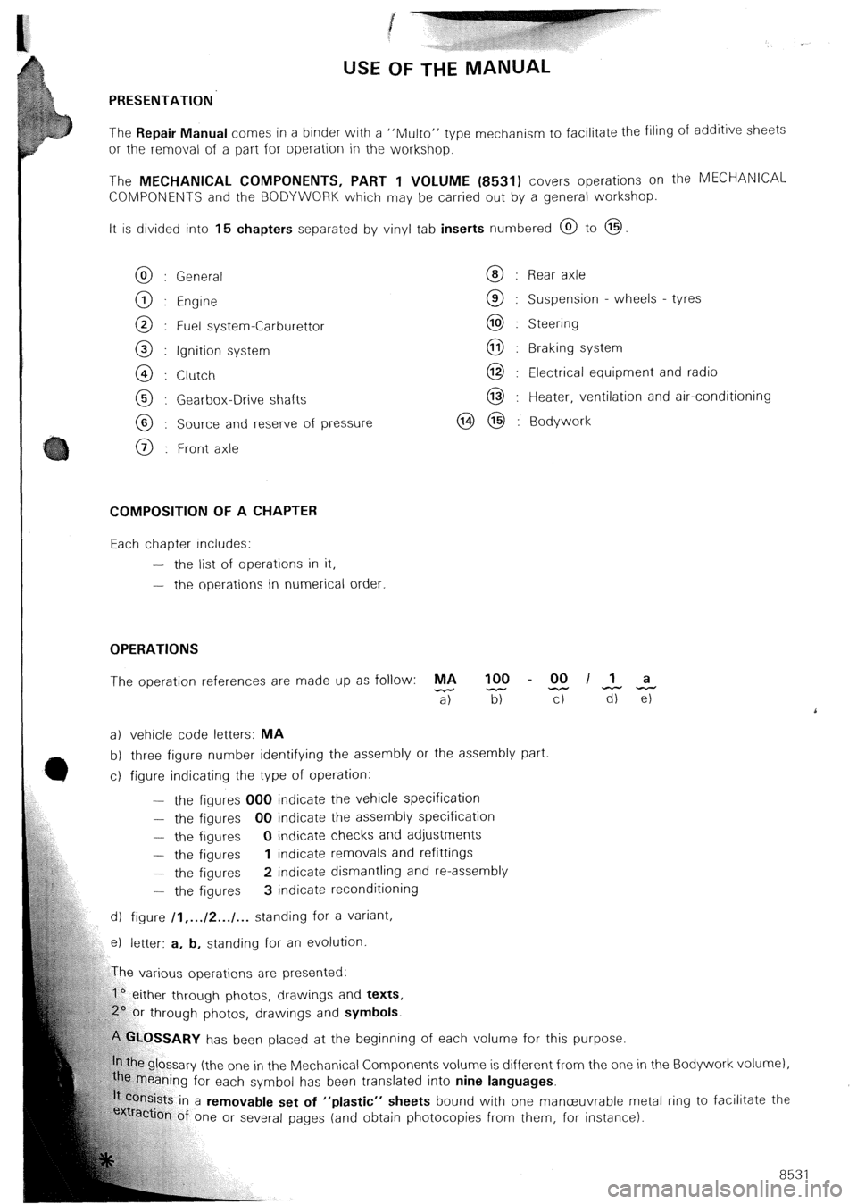
USE OF THE MANUAL
PRESENTATION
The Repair Manual comes in a binder with a “Mu/to” type
mechanism to facilitate the filing of additive sheets
or the removal of a part for operation in the workshop.
The MECHANICAL COMPONENTS, PART 1 VOLUME (8531) covers operations on the MECHANlCAL
COMPONENTS and the BODYWORK which may be carried out by a general workshop.
It is divided into 15 chapters separated by vinyl tab inserts numbered @ to @
General
Engine
Fuel system-Carburettor
Ignition system
Clutch
Gearbox-Drive shafts
Source and reserve of pressure
Front axle Rear axle
Suspension - wheels - tyres
Steering
Braking system
Electrical equipment and radio
Heater, ventilation and air-conditioning
Bodywork
COMPOSITION OF A CHAPTER
Each chapter includes:
-
the list of operations in it,
-
the operations in numerical order.
OPERATIONS
The operation references are made up as follow: MA 100 - 00 II a
-
a) z T-r TiiTz
a) vehicle code letters: MA
b) three figure number identifying the assembly or the assembly part
c) figure indicating the type of operation:
-
the figures 000 indicate the vehicle specification
- the figures 00 indicate the assembly specification
- the figures 0 indicate checks and adjustments
- the figures 1 indicate removals and refittings
- the figures 2 indicate dismantling and re-assembly
-
the figures 3 indicate reconditioning
d) figure /I,... /2.../... standing for a variant,
e) letter: a, b, standing for an evolution
rious operations are presented:
1’ either through photos, drawings and texts,
hrough photos, drawings and symbols.
‘!%.OSSARY has been placed at the beginning of each volume for this purpose.
e glossary (the one in the Mechanical Components volume is different from the one in
caning for each symbol has been translated into nine languages.
kts in a removable set of “plastic” sheets bound with one manceuvrable me
ion of one or several pages (and obtain photocopies from them, for instance). the Bodywork volur nel,
‘tal r ing to facilitate the
85 31
Page 91 of 648

REMOVING AND REFITTING
THE ENGINE/GEARBOX ASSEMBLY
- 2.5 LITRE CX WITH PETROL INJECTION -
REMOVAL
Support the car on stands horizontally, Fig. I using
the three stands 6602-T, in order to facilitate the
removal of the power unit assembly and to reposition
it more easily on the stands.
Depressurize the hydraulic system.
Drain the brake accumulator.
Set the height control to the “low” position
Remove:
- the battery,
- the bonnet,
- the front wheel,
- the spare wheel
- the protection plate located under the spare wheel,
Drain the cooling circuit via the drain hose of the
radiator.
Take off the crankcase drain plug (I 1, Fig. II.
Remove the drive-shafts:
(Refer to Op @ MA.372. l/l)
Uncouple: hoses (6) and (71, Fig. IV (protecting the
alternator from water entry at “a”).
Disconnect the engine cooling fan thermal switch.
Remove the engine heat sink.
Extract, Fig. Ill:
- the screws that secure horn (2) support, passing
through the wheelarch,
- the wheelarch lining. Disconnect:
- wiring harnesses (3) from the battery positive lead,
Fig. Ill,
- the ground cable from the gearbox,
- the wiring harness from the reversing lamp switch.
Remove, Fig. Ill:
- the pressure regulator accumulator,
- pipe (4) between pressure regulator and brake accu-
mulator.
Vehicle with air conditioning option:
- the belt protective cover,
- the air conditioning compressor drive belt
Uncouple:
- the air intake casing position accelerator cable,
- the high pressure pump rubber suction pipe,
- the high pressure pump outlet pipe (5) and its attach-
ment, Fig. Ill.
Disconnect: Fig. V
- the throttle spindle switch (IO),
- knock sensor (14).
Uncouple: Fig. V
- pressure sensor pipe(91,
- supplementary air pipe (I I),
- cylinderhead cover pipe (I 21,
- breather pipe (8).
Remove suction pipe (I 3) situated between the flow-
meter and the turbocharger or between the flowme-
ter and the inlet manifold.
Page 95 of 648

o&ion oi‘i tht: enginr:,
-T.bis (as shown on i/til.irial~oiii,
attaching bracket 6031-
nafu/a//y asp/rafed erg/m with E/7: bracket to bc: fit-
ted on the exhaust pipe, with one screw,
turbo with EN: fit the bracket to the pressure relief
valve outlet,
- tensioner 4061-T (siack).
Place sling 2517-T.bis. under tension, tensioner
4061-T being loosened, Fig. II.
Remove:
- screw (I 1 from the engine bearer, Fig. III.
- nut (3) and screws (4) from the gearbox mounting,
Fig. V (retrieve the shims),
- screw (2) from the torque rod; slacken the other
scl-ew, Fig. IV.
Slightly raise the power unit assembly
Screw tensioner 4061-T fully, Fig. VI and remove
the engine/gearbox assembly:
Before refitting the power unit assembly:
Check the condition of the engine mounting brac-
kets. Replace them if needed.
Adjustment to be tested,
(as per Op.0 MA 733.0/1) Fit the engine crankcase water dralrl plug, fltted with a
~~~in~ torque: 3 mda
Place sling 2517-T.bis, attaching bracket 6031 -T
and tensioner 4061-T; screw the tensioner fully In,
Fig. I and VI.
Engage the engine/gearbox assembly Into Its corr-
partment, Fig. VI.
l-oosen tensioner 4061-T, Fig. II.
Refit: (without tightening)
- engine support bracket
screw (I 1,
- torque rod screw (2)
- gearbox support plate (toyeTher with 1f.s shims).
Tighten:
- the engrne bearer to 10 mdaN, Fig. III
- the torque rod to 9 mdaN, Fig. IV
-. the gearbox support plate fixings, Fig. V:
screws (4): to 3 mdaN
nut (31: to 16.5 mdaN.
Insert the clutch cable into Its ball-joint. Tighten clutch
control support (5). Adjust the clutch , Fig. VII.
Locate, Fig. VIII.
the dual outlet power take off (61.
the oil gauge.
Page 359 of 648

REMOVING AND REFITTING
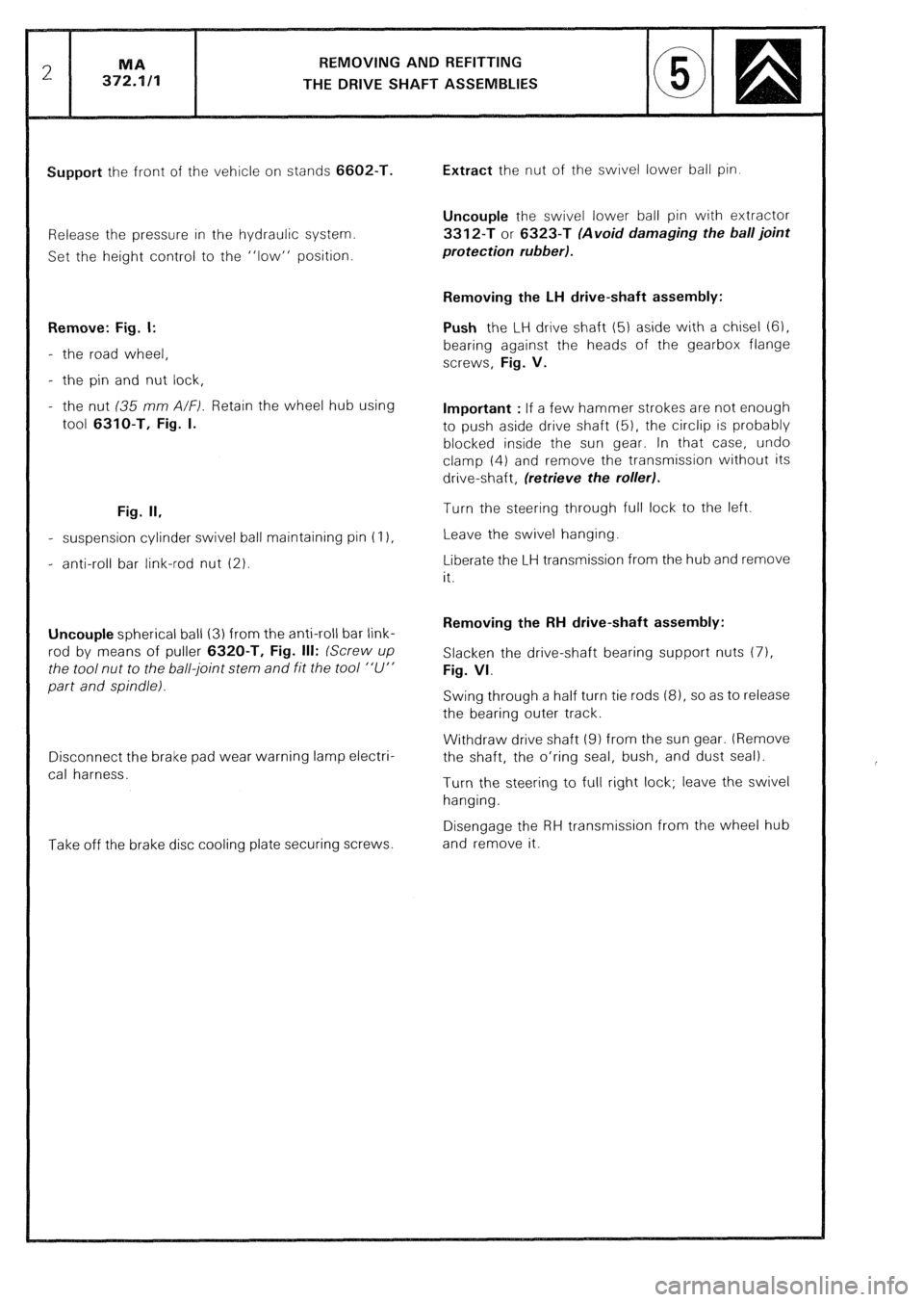
THE DRIVE SHAFT ASSEMBLIES
Support the front of the vehicle on stands 6602-T.
Release the pressure in the hydraulic system.
Set the height control to the “low” position.
Remove: Fig. I:
- the road wheel,
- the pin and nut lock,
- the nut (35 mm A/F). Retain the wheel hub using
tool 6310-T, Fig. I.
Fig. II,
- suspension cylinder swivel ball maintaining pin (I 1,
- anti-roll bar link-rod nut (2).
Uncouple spherical ball (3) from the anti-roll bar link-
rod by means of puller 6320-T, Fig. Ill: (Screw up
the tool nut to the ball-joint stem and fit the tool “U”
part and spindle).
Disconnect the brake pad wear warning lamp electri-
cal harness.
Take off the brake disc cooling plate securing screws. Extract the nut of the swivel lower ball pin.
Uncouple the swivel lower ball pin with extractor
3312-T or 6323-T (Avoid damaging the ball joint
protection rubber).
Removing the LH drive-shaft assembly:
Push the LH drive shaft (5) aside with a chisel (6),
bearing against the heads of the gearbox flange
screws, Fig. V.
Important : If a few hammer strokes are not enough
to push aside drive shaft (51, the circlip is probably
blocked inside the sun gear. In that case, undo
clamp (4) and remove the transmission without its
drive-shaft, (retrieve the rollerl.
Turn the steering through full lock to the left.
Leave the swivel hanging.
Liberate the LH transmission from the hub and remove
it.
Removing the RH drive-shaft assembly:
Slacken the drive-shaft bearing support nuts (71,
Fig. VI.
Swing through a half turn tie rods (81, so as to release
the bearing outer track.
Withdraw drive shaft (9) from the sun gear. (Remove
the shaft, the o’ring seal, bush, and dust seal).
Turn the steering to full right lock; leave the swivel
hanging.
Disengage the RH transmission from the wheel hub
and remove it.