light CITROEN CX 1988 Service Manual
[x] Cancel search | Manufacturer: CITROEN, Model Year: 1988, Model line: CX, Model: CITROEN CX 1988Pages: 648, PDF Size: 95.8 MB
Page 95 of 648

o&ion oi‘i tht: enginr:,
-T.bis (as shown on i/til.irial~oiii,
attaching bracket 6031-
nafu/a//y asp/rafed erg/m with E/7: bracket to bc: fit-
ted on the exhaust pipe, with one screw,
turbo with EN: fit the bracket to the pressure relief
valve outlet,
- tensioner 4061-T (siack).
Place sling 2517-T.bis. under tension, tensioner
4061-T being loosened, Fig. II.
Remove:
- screw (I 1 from the engine bearer, Fig. III.
- nut (3) and screws (4) from the gearbox mounting,
Fig. V (retrieve the shims),
- screw (2) from the torque rod; slacken the other
scl-ew, Fig. IV.
Slightly raise the power unit assembly
Screw tensioner 4061-T fully, Fig. VI and remove
the engine/gearbox assembly:
Before refitting the power unit assembly:
Check the condition of the engine mounting brac-
kets. Replace them if needed.
Adjustment to be tested,
(as per Op.0 MA 733.0/1) Fit the engine crankcase water dralrl plug, fltted with a
~~~in~ torque: 3 mda
Place sling 2517-T.bis, attaching bracket 6031 -T
and tensioner 4061-T; screw the tensioner fully In,
Fig. I and VI.
Engage the engine/gearbox assembly Into Its corr-
partment, Fig. VI.
l-oosen tensioner 4061-T, Fig. II.
Refit: (without tightening)
- engine support bracket
screw (I 1,
- torque rod screw (2)
- gearbox support plate (toyeTher with 1f.s shims).
Tighten:
- the engrne bearer to 10 mdaN, Fig. III
- the torque rod to 9 mdaN, Fig. IV
-. the gearbox support plate fixings, Fig. V:
screws (4): to 3 mdaN
nut (31: to 16.5 mdaN.
Insert the clutch cable into Its ball-joint. Tighten clutch
control support (5). Adjust the clutch , Fig. VII.
Locate, Fig. VIII.
the dual outlet power take off (61.
the oil gauge.
Page 233 of 648

GENERAL FEATURES
OF THE TRANSISTORISED IGNITION SYSTEM
TRANSISTORISED IGNITION
PRINCIPLE OF OPERATION
The plug spark is triggered by distributor (1) which comprises a coil located inside the field of a magnetic circuit
permanent magnet. The magnetic circuit has four fixed branches and four movable branches driven by the distribu-
tor shaft.
When the movable branches, in their rotation, come opposite the fixed ones, a variation of the magnetic field is
brought and current is induced into the sensor winding.
This current, in turn, triggers electronic module (2)
which builds up the current in ignition coil (3) primary winding
and then cuts it off, thus creating a high tension current in the coil secondary winding and triggering a spark from
the plug selected by the distributor rotor arm. IGNITION DISTRIBUTOR (I!
The advance curves are specific for each engine type
N: Distributor rpm
D = Vacuum Dl, in m.bars A:
Distributor degrees 02, in mm.hg
Pick-up coil resistance: 1100 Q sr 10% (990 to 1210 02)
Setting the distributor static timing on the engine is impossible owing to design.
A revolution of the distributor is required to create a variation of the magnetic field which will send a signal to the
module. Consequently, when fitting a distributor, place it in mid-slot; start the engine and adjust the distributor
by means of a timing light or a diagnosis console.
The duration and amplitude of the signal depend on the speed, therefore the DWELL ratio
is not significant.
The air gap between the branches is non-adjustable and it cannot be measured ELECTRONIC MODULE (2)
Intended to operate with the magnetically-triggered distributor.
Do not carry out a check with an ohmmeter since the results would not be significant.
Do not operate the module without cooling (aluminium plate heat sink and heat conductor grease).
The operation of the ignition system is possible with the engine stopped: - connect an earthed sparking plug to
the coil HT lead; short ” + 12 volts” pulses on module red lead (path 5) (with all leads connected, cap lifted) will
generate a spark from the plug: simulation of a signal from the distributor pick up).
Do not operate the module and coil without a plug and HT lead, (It could result in the module being destroyed). IGNITION COIL (3)
The coil must not be kept alive under 12 volts without its module (overheating).
The coil current flow is generated by the module which then reduces it, prior to cutting it off when the engine
ignition timing occurs.
Only use a rev. counter with a UT induction clip.
Page 264 of 648

CHECKING THE IGNITION SYSTEM
USING CHECKING EQUIPMENT OUT 106 029T
The instrument can be utilised on CX 2400 I.E. with naturally aspirated engine and CX 2500 I.E. TURBO. Howe-
ver, on CX 2400 I.E. having an integrated electronic ignition system with a single connector E.C.U., it is neces-
sary to proceed as follows:
- connect the I.E.I. control unit to the black connector of OUT 105 029.T
- set the switch of the apparatus to the “1 connector” position
- I.E.I. with 1 or 2 sensors can be checked with this device.
a) Testing the ignition coil primary winding:
- The warning lamps, one at each coil, blink rythmically with the impulses transmitted to their primary win-
ding. Steady blinks indicate that there is enough current to generate a spark in the secondary winding.
- The switch situated under the warning lamps makes it possible for the primary windings of both coils to
be insulated, by pushing, in the “out of circuit“ position, any interference coming from the HT circuit when
the frequency of illumination for sensor warning lamps is checked.
- If the warning lamps blinking is correct, the failure may be caused by:
- the ignition information to the fuel injection control unit, (paragraph c),
- the secondary winding (coil wires, coils),
- any other item required for a correct operation of the engine such as injection, valve gear, rockers etc.) -
If the warning lamps blinking is not correct, examine the control unit warning lamps, (paragraph b),
b) Testing the sensors: -
The warning lamp connected with the “datum” sensor blinks rythmically with the impulses transmitted by
the peg, i.e. one blink per engine revolution, (2 sensors fitted).
- The warning lamp connected with the “flywheel pick up” sensor, blinks rythmically with the impulses sent ’
by the flywheel teeth.
The frequency of the flashes is such as they can hardly be seen.
Apparently, the lamp stays on, (1 or 2 sensors fitted).
On the CX 2400 I.E. and 2500 I.E. with normally aspirated engine, the vacuum pressure warning lamp lights
up momentarily after a sharp acceleration: this warning lamp is no longer usable on the CX 2500 I.E. with
turbocharger.
c) Tests related with the I.E.I. control unit:
E.C.U. functions: -
The rev. counter warning lamp blinks rythmically with the impulses transmitted to the rev. counter.
- The injection warning lamp blinks rythmically with the impulses sent to the fuel injection control unit
+k 8531
Page 265 of 648

CHECKING THE IGNlTlON ADVANCE
of the I.E.I. system
On CX vehicles fitted with I.E.I.
These vehicles having fixed sensors, are not equipped with TDC sensors
I) Marking the TDC:
Draw a mark on the crankcase, in the opening located next to the flywheel pick up sensor
- Remove the 1st or 4th cylinder sparking plug
- Finding the T.D.C. with a locating peg: jack up the vehicle on one side and engage a gear.
Rotate the road wheel in one direction.
Mark down the place where locating pin will enter the flywheel.
Draw a temporary line on the flywheel ring. Rotate the lifted road wheel in the opposite direction, with
the pin still engaged. Mark the position of the pin in the flywheel ring. Take an average of these two marks-
which corresponds to the TDC. Draw a white paint mark on the flywheel ring, opposite the one on the
crankcase.
- Refit the sparking plug.
2) Testing the development of the speedometer advance curve:
- Connect a phase shifting strobe lamp
- Set the strobe lamp to the 2 cyl. u stroke or 1 cyl. 2 stroke position.
- Disconnect the pipe of the load correction depression operated capsule from the inlet manifold. Blank
off the orifice.
- Run the engine and check the advance curve development.
3) Testing the operation of the air-operated capsule on normally aspirated engines:
- Blank off the vacuum capsule venting orifice.
- Connect a vacuum pump to the capsule pipe.
- Run the engine to 2.000 rpm; record the advance reading.
- Create a 400 mbar depression in the vacuum capsule.
The ignition advance increases by about 15’ and the engine accelerates to 200 rpm approx.
On turbocharged engines:
- Connect a vacuum-pressure pump to the capsule pipe.
- Rotate the engine to 200 rpm. Read the advance.
- Build up a 500 mbar depression in the capsule:
- There will be a 22” increase of the ignition advance, approx. and about a 500 rpm engine acceleration.
- Build up a 500 mbar pressure in the capsule:
- There will be a -1 1 o decrease of the ignition advance, approx. and about a 500 rpm engine slowing down
- Pinking: occurs when the engine speed exceeds 1.000 rpm. The warning lamp should light up in the
following cases:
- anti-knock sensor system broken or short-circuited,
- knock sensor broken or short circuited,
- improper earthing provided by the knock sensor.
- Check the operation with the strobe lamp, and a 2.000 rpm engine speed Record the ignition timing.
- Disconnect the knock sensor:
The ignition advance decreases by IO’ approx.
Page 318 of 648

REPAIR OF THE HYDRAULIC SYSTEM
FITTING PRECAUTIONS
PRECAUTIONS TO BE TAKEN WHEN WORKING ON
THE HYDRAULIC UNITS OR THE SYSTEM
The correct functioning of the entire system presupposes perfect cleanliness of the fluid and the hydraulic
units. Stringent precaut!ons must therefore be taken when working on the hydraulic system and during the
storage of the fluid and components. 1. HYDRAULIC FLUID:
Mineral hydraulic fluid (LHM) is the only suitable type and must be used to the exclusion of all others in the hydrau-
lic system of the car.
This LHM fluid is green in co/our and similar to engine oil.
The use of any other would ruin the rubber rings and seals in the system. 2. RUBBER UNITS AND PARTS:
Suitable components are identified by their green co/our and may only be replaced by genuine replacement
components painted or marked in green.
All rubber components (seals, hoses, diaphragm, etc...) are of a special quality for use with LHM fluid and are
identified by their white or green colour. 3. STORAGE:
Components must be stored, full of fluid and blanked off. Like the piping, they must be protected against shock
and the ingress of dust.
Rubber tubing and joints must be stored away from dust, air, light and heat.
LHM hydraulic fluid must be stored in its original containers carefully sealed. We advise the use of one litre (for
topping up) or five litre cans (for refilling) to avoid having to keep opened containers. 4. CHECKS BEFORE CARRYING OUT WORK:
Before-working on the hydraulic system in case of faulty operation, ensure the following:
a) That the controls or the mechanical linkages of the units or the group of hydraulic units involved are
not stiff in operation
I I
b) and that the HP circuit is under pressure, as follows:
With the engine at idling speed:
- Unscrew the pressure-release screw on the pressure regulator by one turn to one turn and a half: a sound
of leakage should be heard from the regulator.
- Retighten the release screw: cut-out must occur which results in a reduction in the running noise emitted
by the H.P. pump.
If not, check in the following sequence:
- that there is sufficient fluid in the reservoir,
- that the reservoir filter is clean and in good condition,
- that the H.P. pump is primed and there is no air leak on the suction side of the pump,
- that the release screw of the pressure regulator is correctly tightened,
- that sealing ball (2) is in position, (see Fig. I and II, page 5).
Page 319 of 648
REPAIR OF THE HYDRAULIC SYSTEM
FITTING PRECAUTIONS
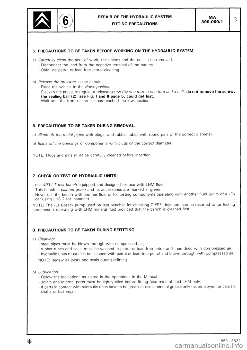
5. PRECAUTIONS TO BE TAKEN BEFORE WORKING ON THE HYDRAULIC SYSTEM:
a) Carrefully clean the aera of work, the unions and the unit to be removed
- Disconnect the lead from the negative terminal of the battery.
- Only use petrol or lead-free petrol cleaning.
b) Release the pressure in the circuits:
- Place the vehicle in the K/OW~~ position.
- Slacken the pressure regulator release screw (by one turn to one turn and a half, do not remove the screw:
the sealing ball (21, see Fig. I and II page 5, could get lost,
- Wait until the front of the car has reached the low position. 6. PRECAUTIONS TO BE TAKEN DURING REMOVAL.
a) Blank off the metal pipes with plugs, and rubber tubes with round pins of the correct diameter
b) Blank off the openings of components with plugs of the correct diameter.
NOTE: Plugs and pins must be carefully cleaned before insertion 7. CHECK OR TEST OF HYDRAULIC UNITS:
- use 4034-T test bench equipped and designed for use with LHM fluid.
- This bench is painted green and its accessories are marked in green.
- Never use the bench with another fluid or for testing components operating with another fluid (units of a c(D))
car using LHS 2 for instance).
NOTE: The uLe Bozec)) pump used on test benches for checking DIESEL injectors can be resorted to for testing,
components operating with LHM mineral fluid provided that the bench is cleaned first. 8. PRECAUTIONS TO BE TAKEN DURING REFITTING.
a 1 Cleaning:
- steel pipes must be blown through with compressed air,
- rubber tubes and seals must be washed in petrol or lead-free petrol and then dried with compressed air,
- hydraulic units must also be cleaned with petrol or lead-free petrol and blown through with compressed air.
NOTE: Renew all joints and seals during refitting
b) Lubrication.
- Follow the indications as stated in the operations in the Manual.
- Joints and internal parts must be lightly oiled before fitting (use mineral fluid LHM only).
- If parts in contact with hydraulic units have to be greased, use a mineral grease only (as employed for cardan
shafts or bearings). +#+
8531-8532
Page 320 of 648
REPAIR OF THE HYDRAULIC SYSTEM
FITTING PRECAUTIONS
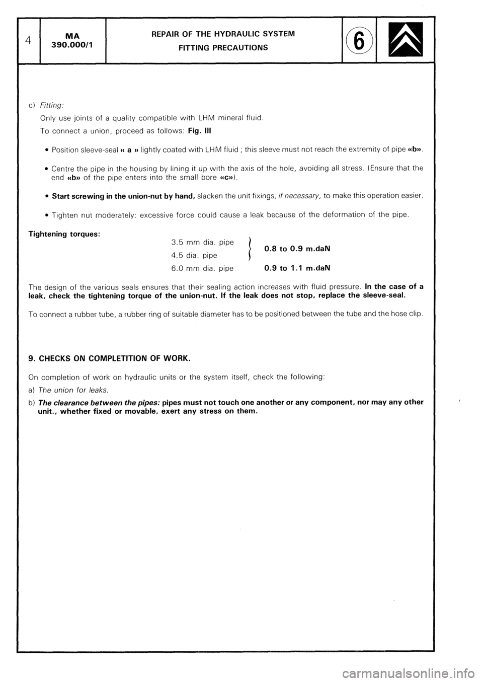
c) Fitting..
Only use joints of a quality compatible with LHM mineral fluid.
To connect a union, proceed as follows: Fig. Ill
0 Position sleeve-seal u a )) lightly coated with LHM fluid ; this sleeve must not reach the extremity of pipe c(b)).
l Centre the pipe in the housing by lining it up with the axis of the hole, avoiding all stress. (Ensure that the
end c
l Tighten nut moderately: excessive force could cause a leak because of the deformation of the pipe.
Tightening torques:
3.5 mm dia. pipe
0.8 to 0.9 m.daN
4.5 dia. pipe
6.0 mm dia. pipe 0.9 to 1.1 m.daN
The design of the various seals ensures that their sealing action increases with fluid pressure. In the case of a
leak, check the tightening torque of the union-nut. If the leak does not stop, replace the sleeve-seal.
To connect a rubber tube, a rubber ring of suitable diameter has to be positioned between the tube and the hose clip.
9. CHECKS ON COMPLETITION OF WORK.
On completion of work on hydraulic units or the system itself, check the following:
a) The union for leaks.
b) The clearance between the pipes: pipes must not touch one another or any component, nor may any other
unit., whether fixed or movable, exert any stress on them.
Page 362 of 648
REMOVING AND REFITTING THE
DRIVE SHAFT ASSEMBLIES
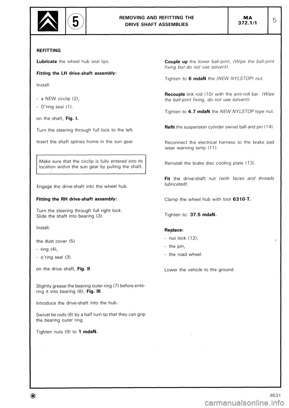
REFITTING
Lubricate the wheel hub seal lips.
Fitting the LH drive-shaft assembly:
install:
- a NEW circlip (21,
- O’ring seal (I).
on the shaft, Fig. I.
Turn the steering through full lock to the left.
Insert the shaft splines home in the sun gear.
Make sure that the circlip is fully entered into its
location within the sun gear by pulling the shaft.
Engage the drive-shaft into the wheel hub.
Fitting the RH drive-shaft assembly:
Turn the steering through full right lock.
Slide the shaft into bearing (3).
Install:
the dust cover (5)
- ring (41,
- o’ring seal (3).
on the drive shaft, Fig. II
Slightly grease the bearing outer ring (7) before ente-
ring it into bearing (8). Fig. Ill.
Introduce the drive-shaft into the hub.
Swivel tie rods (6) by a half turn so that they can grip
the bearing outer ring.
Tighten nuts (9) to 1 mdaN. Couple up the lower ball-joint, (Wipe the ball-joint
fixing but do not use solvent).
Tighten to 6 mdaN the (NEW NYLSTOP) nut.
Recouple link rod (IO) with the anti-roll bar. (Wipe
the ball-joint fixing, do not use solvent).
Tighten to 4.7 mdaN the NEW NYLSTOP type nut.
Refit the suspension cylinder swivel ball and pin (14).
Reconnect the electrical harness to the brake pad
wear warning lamp (I I).
Reinstall the brake disc cooling plate (I 3)
Fit the drive-shaft nut (with faces and threads
lubricatedl.
Clamp the wheel hub with tool 6310-T.
Tighten to: 37.5 mdaN.
Replace:
- nut lock (121,
- the pin,
- the road wheel
Lower the vehicle to the ground
3tc 8531
Page 379 of 648
2 51 O%O,l ELECTRICAL INSTALLATION GENERAL OUTLINES
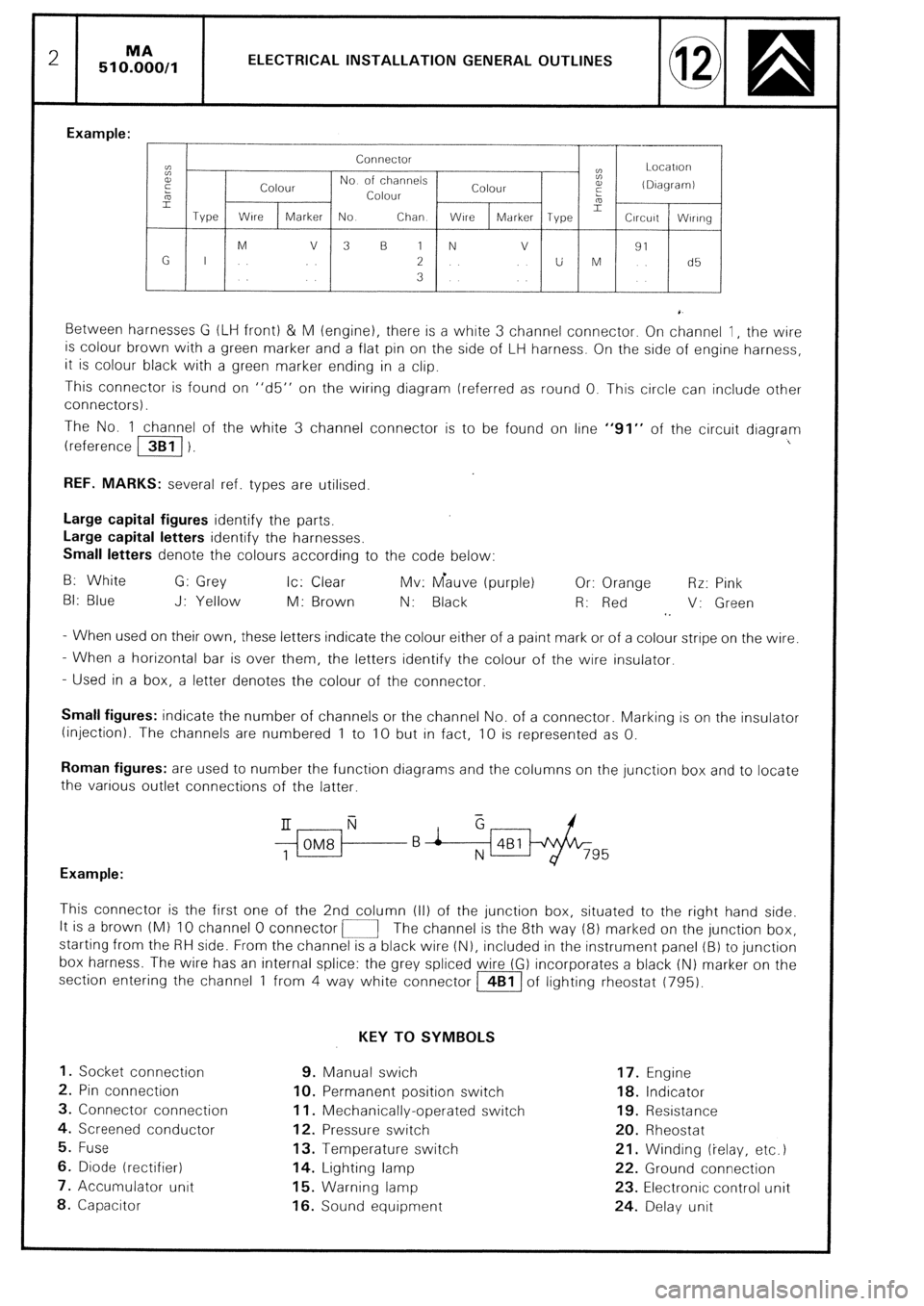
Example:
Connector
cc
t: Locatlori
E
Colour No of channels
Colour a,
(DIagramI
5 Colour :
L
Type Wire 2
Marker No Chan WlrC Marker Type Circuit Wlrlng
M V 3 B 1 N v
91
G I 2 U M d5
3
Between harnesses G (LIH front) & M (engine), there is a white 3 channel connector. On channel 1, the wire
is colour brown with a green marker and a flat pin on the side of LH harness. On the side of engine harness,
it is colour black with a green marker ending in a clip.
This connector is found on “d5” on the wiring diagram (referred as round 0. This circle can include other
connectors).
The No. 1 channel of the white 3 channel connector is to be found on line “91” of the circuit diagram
(reference /3B1/ 1. I
REF. MARKS: several ref. types are utilised.
Large capital figures identify the parts,
Large capital letters identify the harnesses.
Small letters denote the colours according to the code below:
B: White G: Grey Ic: Clear Mv: Gauve (purple) Or: Orange Rr: Pink
BI: Blue J: Yellow M: Brown N: Black R: Red V: Green
1.
- When used on their own, these letters indicate the colour either of a paint mark or of a colour stripe on the wire.
- When a horizontal bar is over them, the letters identify the colour of the wire insulator.
- Used in a box, a letter denotes the colour of the connector.
Small figures: indicate the number of channels or the channel No. of a connector. Marking IS on the insulator
(injection). The channels are numbered 1 to 10 but in fact, 10 is represented as 0.
Roman figures: are used to number the function diagrams and the columns on the junction box and to locate
the various outlet connections of the latter.
$ii-f--B i &Bl/+&-
795
Example:
This connector is the first one of the 2nd column (II) of the junction box, situated to the right hand side.
It is a brown (Ml IO channel 0 connector i-1 The channel is the 8th way (8) marked on the junction box,
starting from the RH side. From the channel is a black wire (N), included in the instrument panel (B) to junction
box harness. The wire has an internal splice: the grey spliced wire (G) incorporates a black (N) marker on the
section entering the channel 1 from 4 way white connector m of lighting rheostat (795).
KEY TO SYMBOLS
1. Socket connection 9. Manual swich 17. Engine
2. Pin connection IO. Permanent position switch 18. Indicator
3. Connector connection 11. Mechanically-operated switch 19. Resistance
4. Screened conductor 12. Pressure switch 20. Rheostat
5. Fuse 13. Temperature switch 21. Winding (ielay, etc.)
6. Diode (rectifier) 14. Lighting lamp 22. Ground connection
7. Accumulator unit 15. Warning lamp 23. Electronic control unit
8. Capacitor 16. Sound equipment 24. Delay unit
Page 382 of 648
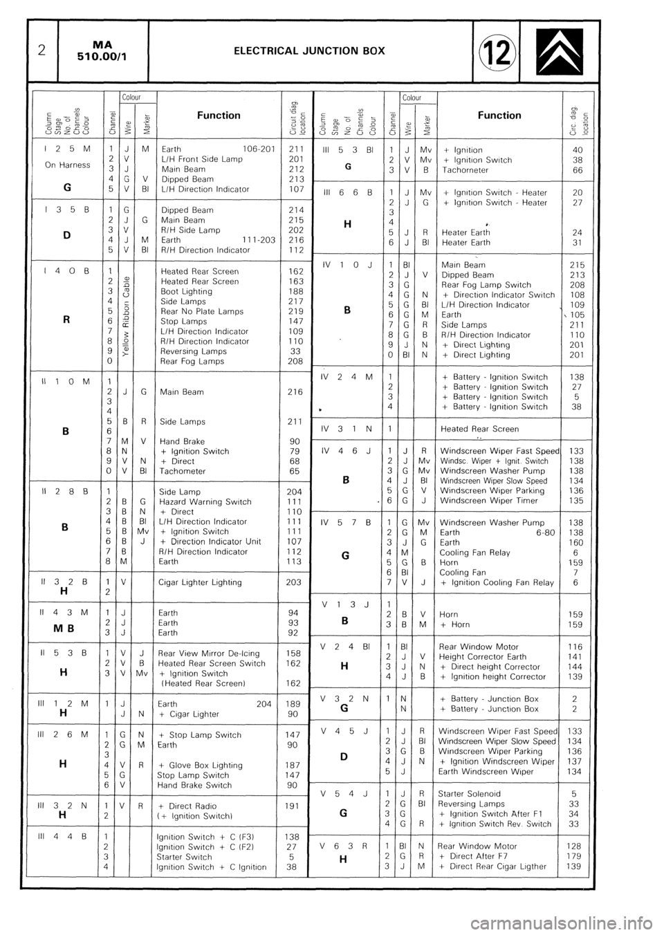
2 MA
510.00/1 ELECTRICAL JUNCTION BOX
Colour Colour
CJ)
”
2
a,
E --Pi- Function ”
i
-1
5 z 2 iz az?i”; cg Function
,%“~o” -0
2% z 2:
om 02’ 2%
Es p 2 f
“v)Z”” i53 s 22
S2r”~S 0% zi ‘i’ F
G,c
125M 1JM Earth 106-201 211
III 5 3 Bl 1 J Mv + lgnttron 40
On Harness 3 J 2 v L/H Front Srde Lamp 201
2 V Mv
G + lgnrtion Swatch 38
Main Beam 212 3V B Tachometer 66
4G V Dipped Beam
G 213
5 V BI L/H Drrectron lndrcator 107
III 6 6 B 1 J Mv + lgnrtron Swatch - Heater 20
l35B 1G 2J G + lgnrtron Switch - Heater 27
Drpped Beam 214
3
2J G Marn Beam 215
H 4
D 3 v R/H Side Lamp 202
4 J M 5J R
Earth Heater Eart; 24
11 I-203 216
5 V BI 6 J BI Heater Earth 31
R/H Direction lndrcator 112
I408 1 Heated Rear Screen IV 1 0 J 1 BI
162 Main Beam 215
2 2 Heated Rear Screen 2 J V
163 Dipped Beam 213
3 s Boot Lighting 3 G
188 Rear Fog Lamp Swatch
208
4 Side Lamps 4G N
217 + Directron Indicator Swatch 108
5 5
Rear No Plate Lamps 219
B 5 G BI L/H Drrection lndrcator I 109
R 6 2
Stop Lamps 6 G M Earth
147 I105
E 7G R Side Lamps
7 3 L/H DIrectron lndrcator 109 211
8 L? R/H Drrectron Indicator 8G B
110 R/H Directron lndrcator 110
9 t” Reversing Lamps 33 9 J N + Direct Lrghtrng 201
0 Rear Fog Lamps 208 0 BI N + Drrect Lrghting 201
IllOM 1 IV24M 1 + Battery lgnttron Switch 138
2J G Marn Beam 216 2 + Battery lgnrtron Swatch 27
3 3 + Battery lgnttion Switch 5
4 * 4 + Battery - lgnitron Swatch 38
56 R Side Lamps 211 .
B 6 IV31N 1 Heated Rear Screen
7M V Hand Brake 90 I.
8 N + Ignition Switch 79 IV46J 1 J R Windscreen Wiper Fast Speed 133
9V N + Direct 68 2 J Mv Wrndsc Wtper t lgnrt Swatch 138
0 V BI Tachometer 65 3 G Mv Windscreen Washer Pump
B 138
4 J BI Wrndscreen Wiper Slow Speed 134
II288 1 Side Lamp 204 5G v Windscreen Wiper Parkrng 136
2 B G Hazard Warning Switch 111 .6 G J Windscreen Wiper Timer 135
3B N + Drrect 110 .
B 4 B BI L/H Direction Indicator 111
IV 5 7 B 1 G Mv Windscreen Washer Pump 138
5 6 Mv + lgnitron Switch 111
2 G M Earth 6-80 138
6B J + Drrection Indicator Unit 107
3J G Earth
7 0 160
R/H Direction Indicator 112
G 4 M Cooling Fan Relay 6 a M Earth 113
5G B Horn 159
6 BI Cooling Fan 7
ll32B 1 V Cigar Lrghter Lighting 203 7V J
H 2 + lgnitron Cooling Fan Relay 6
II43M 1 J V13J 1
Earth 94
2 J 2 B V Horn
Earth 93
B 159
MB 3 B M
3 J Earth + Horn
92 159
II538 1 V J Rear View Mtrror De-lcrng V 2 4 BI 1 BI
158 Rear Window Motor
116
2v B Heated Rear Screen Switch 2J V
162 Height Corrector Earth 141
H H 3 V Mv + Ignition Switch 3J N + Drrect height Corrector 144
4J B + lgnrtron herght Corrector 139
(Heated Rear Screen) 162
lll12M 1 J Earth 204 189 V32N IN + Battery Junction Box 2
H J N + Crgar Lighter 90 G N + Battery Junctron Box 2
Ill 2 6 M 1 G N + Stop Lamp Switch 147 V45J 1 J R Wrndscreen Wrper Fast Speed 133
2 G M Earth 90 2 J BI Windscreen Wiper Slow Speed 134
3
D 3 G B Windscreen Wrper Parking 136
H 4V R + Glove Box Lrghting 187 4J N + lgnitron Windscreen Wiper 137
5 G Stop Lamp Switch 147 5 J Earth Windscreen Wiper 134
6 V Hand Brake Swatch 90
V54J IJ R Starter Solenord 5
III 3 2 N 1 V R + Direct Radro 191 2 G Bi Reversrng Lamps 33
H 2 ( + lgnrtion Swrtchl G 3 G + lgnrtron Swatch After Fl 34
4G R + lgnrtron Swatch Rev Switch 33
lll44B 1 lgnttron Swatch + C iF3) 138 -
2 lgnrtron Switch + C tF2) 27 V 6 3 R 1 BI N Rear Wrndow Motor 128
3 Starter Swatch 5
H 2G R t Direct After F7 179
4 lgnrtion Switch -t C lgnrtron 38 3J M + Dtrect Rear Crgar Lrgther 139