piston CITROEN CX 1988 Service Manual
[x] Cancel search | Manufacturer: CITROEN, Model Year: 1988, Model line: CX, Model: CITROEN CX 1988Pages: 648, PDF Size: 95.8 MB
Page 99 of 648
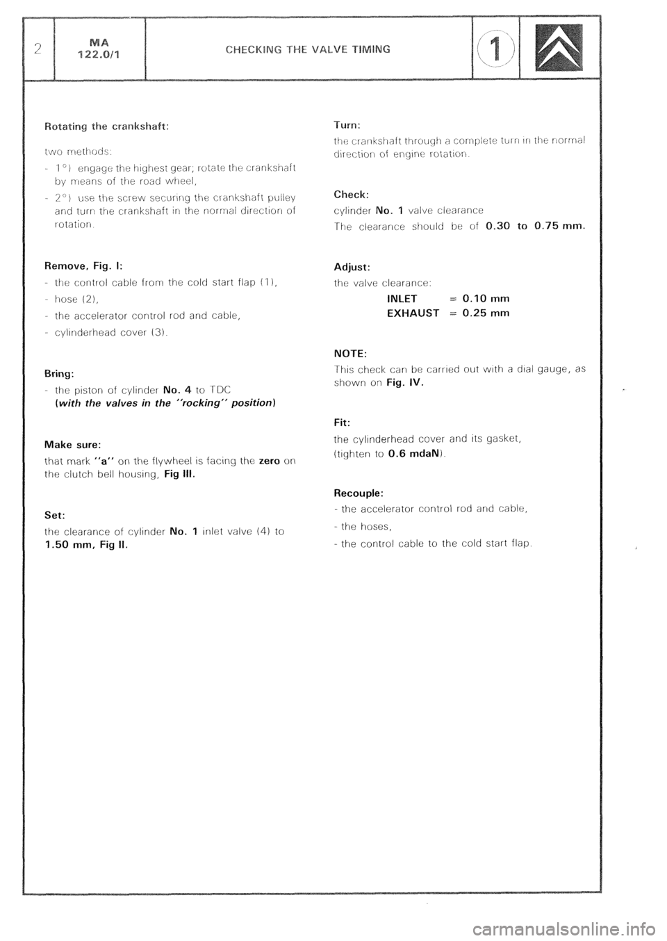
and turn ti-re crankshafi irl the norrnai direct~or~ of
I otatiorj
Remove, Fig. I:
- the co~llrol cable frorn the cold start flap (I 1,
- hose
(21,
- the accelerator control rod and cable,
- cylinderhead cover (3).
Bring:
- the piston of cylinder No. 4 to TDC
(with the valves in the “rocking” position)
Make sure:
that mark “a” on the flywheel is facing the zero on
the clutch bell housing, Fig III.
Set:
the clearance of cylinder No. 1 inlet valve (4) to
1.50 mm, Fig II. Check:
cylinder 0. 1 valve clearance
The clearance should be of 0.30 to 0.75 mm.
Adjust:
the valve clearance:
INLET = 0.10 mm
EXHAUST = 0.25 mm
NOTE:
This check can be carried out with a dial gauge, as
shown on Fig. IV.
Fit:
the cyllnderhead cover and its gasket,
(tighten to 0.6 mdaN).
Recouple:
- the accelerator control rod and cable,
- the hoses,
- the control cable to the cold start flap.
Page 102 of 648
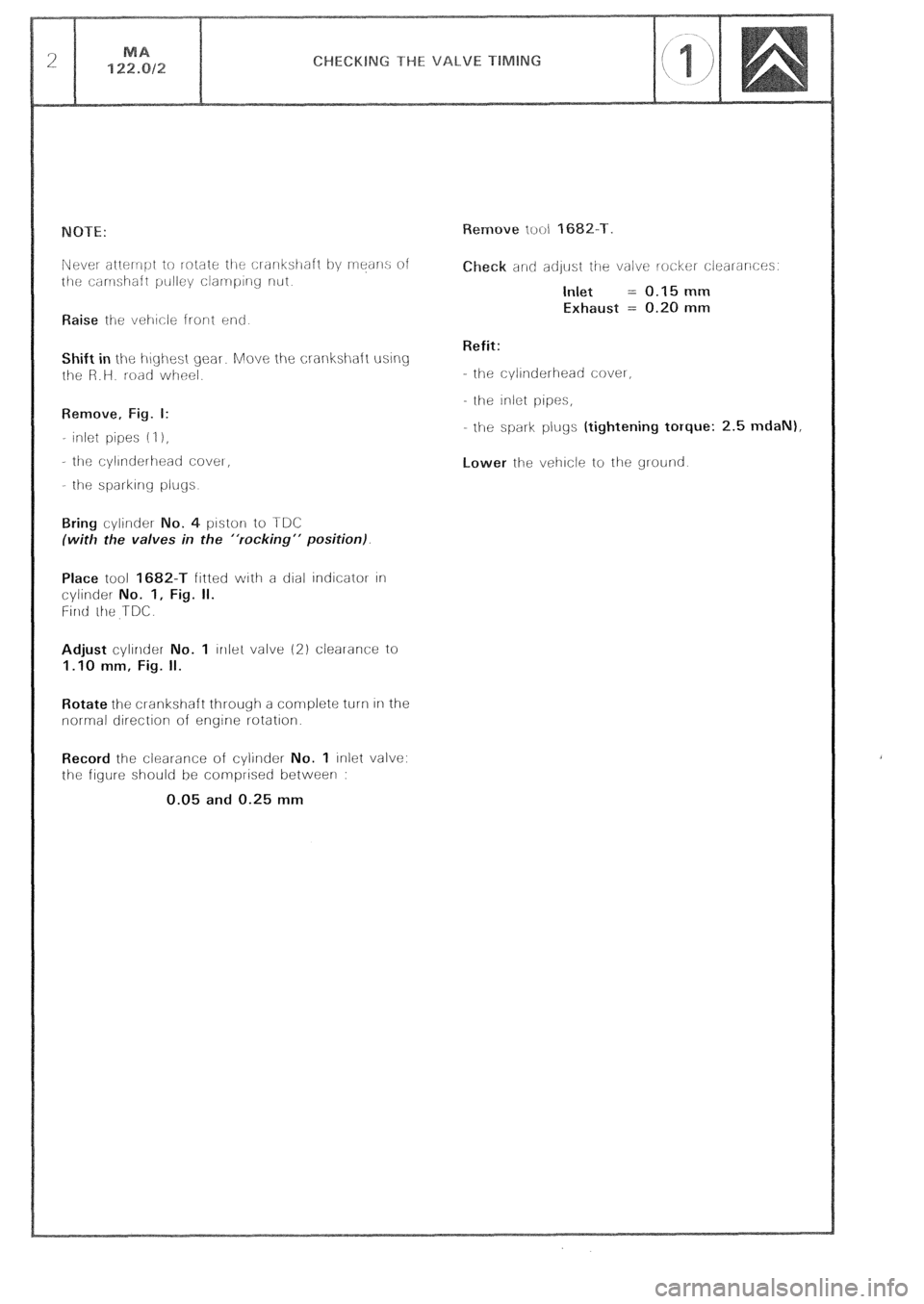
Raise ihe vei-~cle front end
Shift in the i-\~yi-\est gear. Move the crankshaft using
t!le R.H. road wheel.
Remove, Fig. I:
- inlet pipes (I 1,
- tilt: cyllnderlleati CoveI,
- the sparkIng plugs
o. 4 piston to TDC
(with the valves in the “rocking” position).
Place tool 1682-T fitted with a dial indicator In
cylinder No. 1, Fig. II.
Firlti ihe TDC.
Adjust cylinder No. 1 lrllel valve (2) clearance to
1.10 mm, Fig. II.
Rotate the cl-ankshaft through a complete turn In the
normal direction of engine rotation.
Record the clearance of cylirlder No. 1 inlet valve:
the figure should be comprised between :
0.05 and 0.25 mm eck and adlust ihe valve locker clearances.
Inlet = 0.15 mm
Exhaust = 0.20 mm
Refit:
- the cylinderhead cover,
the inlet pipes,
- the spark plugs (tightening torque: 2.5 mdaN),
Lower the vehicle to the ground
Page 108 of 648
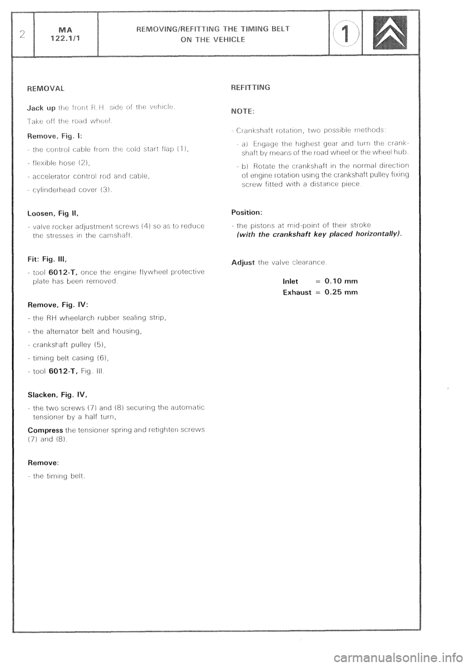
loosen, Fig II,
- valve rocket adjustrnr:nt screws (4) so as to reduce
the stresses irl the camshaft.
Fit: Fig. 111,
- tool 6012-T, once the engine flywheel protective
plate has been rernoved
Remove, Fig. IV:
- the HH wheelarch rubber sealing strtp,
- the al&l-nator belt and housing,
- crankshaft pulley (5),
- timing belt casing 161,
- tool
6012-T, Fig. III
Slacken, Fig. IV,
- the two XI-ews (7) and 18) securing the autornatlc
tensioner by a half turn,
Compress the tensioner spring and retighterl screws
(71 and 18).
Remove:
the timing belt. Crarlkshaft rotation, two pnss~ble rrrothotls
a) i-rlgage the irighest gear and tul n the clank-
shaft by means oi the road wheel OI the wheel i-tub
b) Rotate ti-le crankstlaft 1i1 the normal direction
of eqne rotation using the crankshaft pulley fixing
screw fitted with a ciistsnce piece
Position:
- the pistons at mid-point of their stroke
ith the crankshaft key placed horizontally).
djust the valve clearance
Inlet = 0.10 mm
Exhaust = 0.25 mm
Page 157 of 648
GENERAL FEATURES OF THE CARBURATION
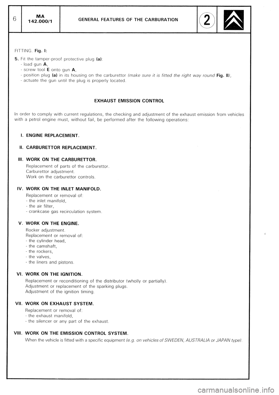
FITTING. Fig. I:
5. FIN the tamper-proof protective plug (a):
- load gun A,
- screw tool E onto gun A,
- position plug (a) in its housing on the carburettor (make sure it is fitted the right way round Fig. 111,
- actuate the gun until the plug is properly located.
EXHAUST EMISSION CONTROL
In order to comply with current regulations, the checking and adjustment of the exhaust emission from vehicles
with a petrol engine must, without fail, be performed after the following operations:
I. ENGINE REPLACEMENT.
II. CARBURETTOR REPLACEMENT.
Ill. WORK ON THE CARBURETTOR.
Replacement of parts of the carburettor.
Carburettor adjustment.
Work on the carburettor controls.
IV. WORK ON THE INLET MANIFOLD.
Replacement or removal of:
- the inlet manifold,
- the air filter,
- crankcase gas recirculation system
V. WORK ON THE ENGINE.
Rocker adjustment.
Replacement or removal of:
- the cylinder head,
- the camshaft,
- the rockers,
- the valves,
- the liners and pistons.
VI. WORK ON THE IGNITION.
Replacement or reconditioning of the distributor (wholly or partially)
Adjustment or replacement of the sparking plugs.
Adjustment of the ignition timing.
VII. WORK ON EXHAUST SYSTEM.
Replacement or removal of:
- the exhaust manifold,
- the silencer or any part of the exhaust.
VIII. WORK ON THE EMISSION CONTROL SYSTEM.
When the vehicle is fitted with a specific equipment (e.g. on vehicles of SWEDEN, AUSTRALlA or JAPAN type)
Page 326 of 648
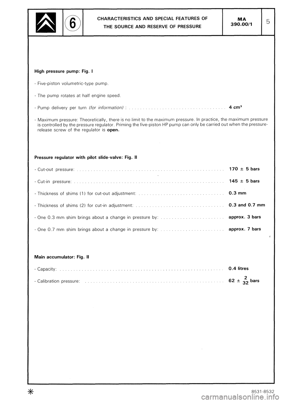
CHARACTERISTICS AND SPECIAL FEATURES OF
THE SOURCE AND RESERVE OF PRESSURE
High pressure pump: Fig. I
- Five-piston volumetric-type pump.
- The pump rotates at half engine speed
- Pump delivery per turn (for information) : 4 cm3
- Maximum pressure: Theoretically, there is no limit to the maximum pressure. In practice, the maximum pressure
is controlled by the pressure regulator. Priming the five-piston HP pump can only be carried out when the pressure-
release screw of the regulator is open.
Pressure regulator with pilot slide-valve: Fig. II
- Cut-out pressure:
- Cut-in pressure:
- Thickness of shims (I ) for cut-out adjustment:
- Thickness of shims (2) for cut-in adjustment:
- One 0.3 mm shim brings about a change in pressure by:
- One 0.7 mm shim brings about a change in pressure by: 170 + 5 bars
145 +: 5 bars
0.3 mm
0.3 and 0.7 mm
approx. 3 bars
approx. 7 bars
Main accumulator: Fig. II
- Capacity: 0.4 litres
- Calibration pressure: 62 rt 322 bars *
8531-8532