torque CITROEN CX 1988 Service Manual
[x] Cancel search | Manufacturer: CITROEN, Model Year: 1988, Model line: CX, Model: CITROEN CX 1988Pages: 648, PDF Size: 95.8 MB
Page 3 of 648
The special tool nurnbers and photos appear in the operation description as the work progresses.
The tools referenced OUT followed by 6
figures and ending in the letter “T” are sold by the Replacement
Parts Department to FRANCE and EXPORT networks.
The tools referenced with 4
figures followed by the letter “T” are sold to FRANCE by the Societe FENWICK,
Departement AMA :
24, boulevard Biron, 93404 SAINT-OUEN. Tel. : 42.52.67.00, and to the EXPORT network by CITROEN.
The tools referenced MR must be made up by the repairer himself TOOLS
For each chapter, the photos
end of the list of operations. of the special
tools required for proper complei :ion of the work, are given at the
TIGHTENING TORQUES:
The tightening torques are expressed in metre Decanewton (mdaN), the official torque measuring unit:
0.981 mdaN = 1 mkg (former measuring unit).
In practice, 1 mdaN = 1 mkg.
UPDATING THE MANUAL WITH ADDITIVES:
Additives should be ordered immediately on receipt of the DOCUMENTATION BULLETIN announcing that
they are issued.
The updated sheets must be added to the existing pages in the manual or replace the corresponding ones. They
are identified by spots located to the left of the shortened volume number placed at the bottom right hand side
of the recta page:
Example : 1 spot
l 8531 additive no. 1 ; 2 spots l * 8531 additive no. 2, etc.
IMPORTANT NOTE:
For all technical information, please apply to:
CENTRE TECHNIQUE CITROEN
Division Apres-Vente
Service Technique
Chemin Vicinal no 2 - 78140 VELIZY
TBI. : 45.37.30.30.
1) ;'.
. .
. .::, _ “*:jy%.
-;'1*,,
':; . .
Page 90 of 648
RECOMMENDED TOOLS
Removing and refitting the power unit assembly 6602-T
2517-T.bis
406 1 -T
6031 -T
Set of three stands
Lifting sling.
VISA anti-roll bar tensioning device
Attaching bracket (for the petrol turbo engine)
Removing and refitting the drive-shafts 3312-T
or 6323-T
6310-T
6320-T
Lower arm ball-joint extractor with bosses
Lower arm ball-joint extractor, with or without bosses
Wheel hub locking tool.
Anti-roll bar link rod puller
- Torque wrench (40 m.daN)
- Bush 35 mm accross flats
+K 8531
Page 95 of 648

o&ion oi‘i tht: enginr:,
-T.bis (as shown on i/til.irial~oiii,
attaching bracket 6031-
nafu/a//y asp/rafed erg/m with E/7: bracket to bc: fit-
ted on the exhaust pipe, with one screw,
turbo with EN: fit the bracket to the pressure relief
valve outlet,
- tensioner 4061-T (siack).
Place sling 2517-T.bis. under tension, tensioner
4061-T being loosened, Fig. II.
Remove:
- screw (I 1 from the engine bearer, Fig. III.
- nut (3) and screws (4) from the gearbox mounting,
Fig. V (retrieve the shims),
- screw (2) from the torque rod; slacken the other
scl-ew, Fig. IV.
Slightly raise the power unit assembly
Screw tensioner 4061-T fully, Fig. VI and remove
the engine/gearbox assembly:
Before refitting the power unit assembly:
Check the condition of the engine mounting brac-
kets. Replace them if needed.
Adjustment to be tested,
(as per Op.0 MA 733.0/1) Fit the engine crankcase water dralrl plug, fltted with a
~~~in~ torque: 3 mda
Place sling 2517-T.bis, attaching bracket 6031 -T
and tensioner 4061-T; screw the tensioner fully In,
Fig. I and VI.
Engage the engine/gearbox assembly Into Its corr-
partment, Fig. VI.
l-oosen tensioner 4061-T, Fig. II.
Refit: (without tightening)
- engine support bracket
screw (I 1,
- torque rod screw (2)
- gearbox support plate (toyeTher with 1f.s shims).
Tighten:
- the engrne bearer to 10 mdaN, Fig. III
- the torque rod to 9 mdaN, Fig. IV
-. the gearbox support plate fixings, Fig. V:
screws (4): to 3 mdaN
nut (31: to 16.5 mdaN.
Insert the clutch cable into Its ball-joint. Tighten clutch
control support (5). Adjust the clutch , Fig. VII.
Locate, Fig. VIII.
the dual outlet power take off (61.
the oil gauge.
Page 102 of 648
Raise ihe vei-~cle front end
Shift in the i-\~yi-\est gear. Move the crankshaft using
t!le R.H. road wheel.
Remove, Fig. I:
- inlet pipes (I 1,
- tilt: cyllnderlleati CoveI,
- the sparkIng plugs
o. 4 piston to TDC
(with the valves in the “rocking” position).
Place tool 1682-T fitted with a dial indicator In
cylinder No. 1, Fig. II.
Firlti ihe TDC.
Adjust cylinder No. 1 lrllel valve (2) clearance to
1.10 mm, Fig. II.
Rotate the cl-ankshaft through a complete turn In the
normal direction of engine rotation.
Record the clearance of cylirlder No. 1 inlet valve:
the figure should be comprised between :
0.05 and 0.25 mm eck and adlust ihe valve locker clearances.
Inlet = 0.15 mm
Exhaust = 0.20 mm
Refit:
- the cylinderhead cover,
the inlet pipes,
- the spark plugs (tightening torque: 2.5 mdaN),
Lower the vehicle to the ground
Page 111 of 648
- crankshaft key horrrontally (with mark “c” stagge-
rred by 5’ upwards),
- mark “a” or “d” on camshaft,
- mark “b” on the rntermedrate shaft.
- Each timing mark on the belt must line up with the
tooth wheel marks.
Fit the belt (avoid contact with oil or grease).
Release, Fig. I and 111,
- tensioner roller screws (I 1 and 12) (let the spring act)
then tighten the screws.
Turn:
- the crankshaft 180’ clockwise.
Do not turn backwards
Release:
- the tensioner roller fixing screws then retrghten
starting with the upper screw (I ), Fig. I and Ill.
Turn:
- the crankshaft a further two turns clockwise.
Slacken, Fig. I and Ill:
- tensioner roller screws (1) and (21, (let the spring
react),
- then retighten starting with screw (I 1.
Fit:
- tool 6012-T., Fig. II. Install, Fig. lb:
the trming belt casing,
crankshaft pulley 13),
trghten screw (4)
to 8 mdaN on engine --r-829.A5
to 12.5 mdaN on engrne -+J6T.A5QQ
- the alternator belt and cover,
- the wheelarch rubber sealing strip.
Remove, Fig. II,
- tool 6012-T.
Fit:
- the cylinder head cover and gasket
ttightenrng torque: 0.6 mdaN).
Recouple:
- the accelerator control rod,
- the flexible hose,
- the cold start flap control cable.
Refit:
- the wheel,
Lower the vehicle to the ground.
NOTE:
- Camshaft toothed pulleys of engines 829.A5 and
J6T.A500 are identical but the fitment is different,
Fig. I.
- If, after carrying out the belt tensioning operation,
the timing belt is noisy when the engine is hot,
retension the belt with the engine hot.
Page 307 of 648
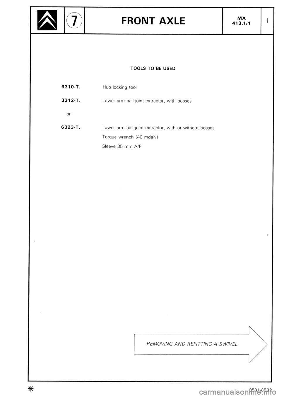
FRONT AXLE
TOOLS TO BE USED
631 O-T.
3312-T.
or 6323-T.
Hub locking tool
Lower arm ball-joint extractor, with bosses
Lower arm ball-joint extractor, with or without bosses
Torque wrench (40 mdaN) Sleeve 35
mm A/F
REMOVING AND REFITTING A SWIVEL
+I+ 8531-8532
Page 312 of 648
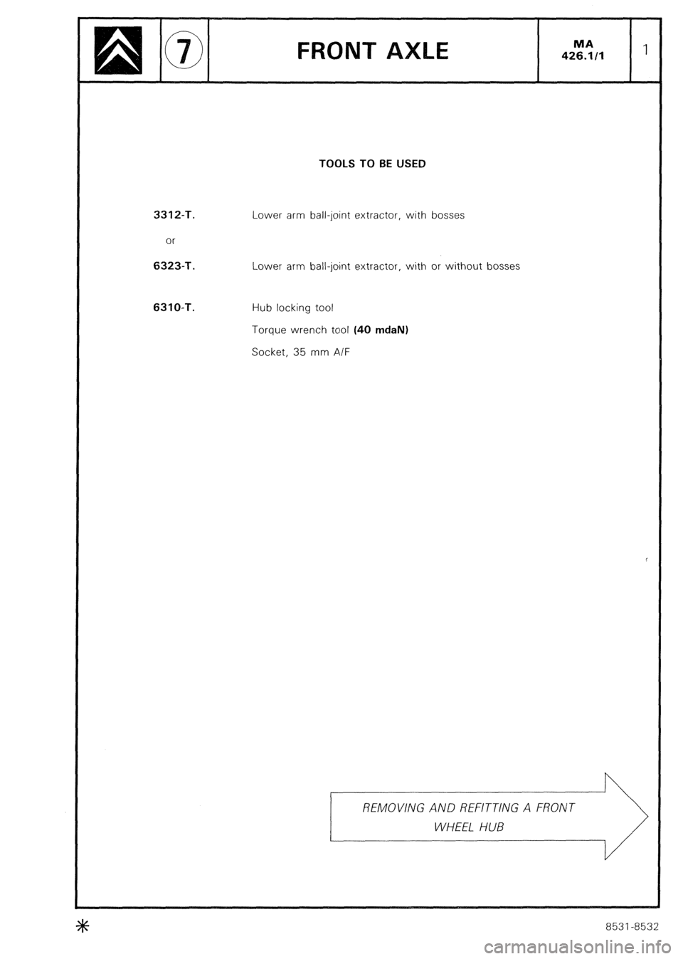
TOOLS TO BE USED
3312-T.
or 6323-T.
6310-T.
Lower arm ball-joint extractor, with bosses
Lower arm ball-joint extractor, with or without bosses
Hub locking tool
Torque wrench tool (40 mdaN)
Socket, 35 mm A/F
REMOVING AND REFITTING A FRONT \ij
8531-8532
Page 320 of 648
REPAIR OF THE HYDRAULIC SYSTEM
FITTING PRECAUTIONS
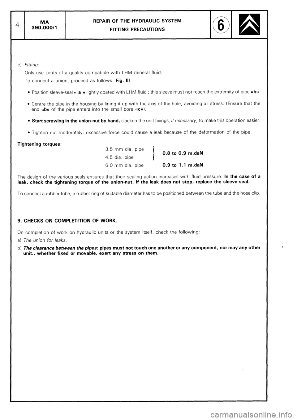
c) Fitting..
Only use joints of a quality compatible with LHM mineral fluid.
To connect a union, proceed as follows: Fig. Ill
0 Position sleeve-seal u a )) lightly coated with LHM fluid ; this sleeve must not reach the extremity of pipe c(b)).
l Centre the pipe in the housing by lining it up with the axis of the hole, avoiding all stress. (Ensure that the
end c
l Tighten nut moderately: excessive force could cause a leak because of the deformation of the pipe.
Tightening torques:
3.5 mm dia. pipe
0.8 to 0.9 m.daN
4.5 dia. pipe
6.0 mm dia. pipe 0.9 to 1.1 m.daN
The design of the various seals ensures that their sealing action increases with fluid pressure. In the case of a
leak, check the tightening torque of the union-nut. If the leak does not stop, replace the sleeve-seal.
To connect a rubber tube, a rubber ring of suitable diameter has to be positioned between the tube and the hose clip.
9. CHECKS ON COMPLETITION OF WORK.
On completion of work on hydraulic units or the system itself, check the following:
a) The union for leaks.
b) The clearance between the pipes: pipes must not touch one another or any component, nor may any other
unit., whether fixed or movable, exert any stress on them.
Page 358 of 648
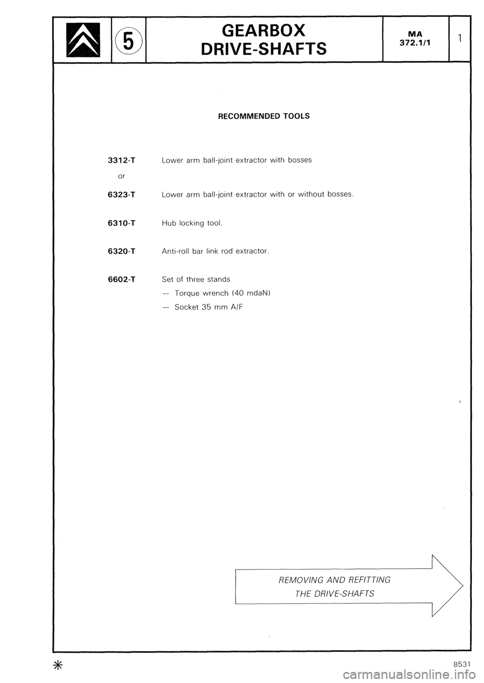
RECOMMENDED TOOLS
3312-T
or 6323-T
Lower arm ball-joint extractor with bosses
Lower arm ball-joint extractor with or without bosses 6310-T
Hub locking tool 6320-T
Anti-roll bar link rod extractor 6602-T
Set of three stands
-- Torque wrench (40 mdaN)
- Socket 35 mm A/F \/,
8531