warning light CITROEN CX 1988 Service Manual
[x] Cancel search | Manufacturer: CITROEN, Model Year: 1988, Model line: CX, Model: CITROEN CX 1988Pages: 648, PDF Size: 95.8 MB
Page 264 of 648

CHECKING THE IGNITION SYSTEM
USING CHECKING EQUIPMENT OUT 106 029T
The instrument can be utilised on CX 2400 I.E. with naturally aspirated engine and CX 2500 I.E. TURBO. Howe-
ver, on CX 2400 I.E. having an integrated electronic ignition system with a single connector E.C.U., it is neces-
sary to proceed as follows:
- connect the I.E.I. control unit to the black connector of OUT 105 029.T
- set the switch of the apparatus to the “1 connector” position
- I.E.I. with 1 or 2 sensors can be checked with this device.
a) Testing the ignition coil primary winding:
- The warning lamps, one at each coil, blink rythmically with the impulses transmitted to their primary win-
ding. Steady blinks indicate that there is enough current to generate a spark in the secondary winding.
- The switch situated under the warning lamps makes it possible for the primary windings of both coils to
be insulated, by pushing, in the “out of circuit“ position, any interference coming from the HT circuit when
the frequency of illumination for sensor warning lamps is checked.
- If the warning lamps blinking is correct, the failure may be caused by:
- the ignition information to the fuel injection control unit, (paragraph c),
- the secondary winding (coil wires, coils),
- any other item required for a correct operation of the engine such as injection, valve gear, rockers etc.) -
If the warning lamps blinking is not correct, examine the control unit warning lamps, (paragraph b),
b) Testing the sensors: -
The warning lamp connected with the “datum” sensor blinks rythmically with the impulses transmitted by
the peg, i.e. one blink per engine revolution, (2 sensors fitted).
- The warning lamp connected with the “flywheel pick up” sensor, blinks rythmically with the impulses sent ’
by the flywheel teeth.
The frequency of the flashes is such as they can hardly be seen.
Apparently, the lamp stays on, (1 or 2 sensors fitted).
On the CX 2400 I.E. and 2500 I.E. with normally aspirated engine, the vacuum pressure warning lamp lights
up momentarily after a sharp acceleration: this warning lamp is no longer usable on the CX 2500 I.E. with
turbocharger.
c) Tests related with the I.E.I. control unit:
E.C.U. functions: -
The rev. counter warning lamp blinks rythmically with the impulses transmitted to the rev. counter.
- The injection warning lamp blinks rythmically with the impulses sent to the fuel injection control unit
+k 8531
Page 265 of 648

CHECKING THE IGNlTlON ADVANCE
of the I.E.I. system
On CX vehicles fitted with I.E.I.
These vehicles having fixed sensors, are not equipped with TDC sensors
I) Marking the TDC:
Draw a mark on the crankcase, in the opening located next to the flywheel pick up sensor
- Remove the 1st or 4th cylinder sparking plug
- Finding the T.D.C. with a locating peg: jack up the vehicle on one side and engage a gear.
Rotate the road wheel in one direction.
Mark down the place where locating pin will enter the flywheel.
Draw a temporary line on the flywheel ring. Rotate the lifted road wheel in the opposite direction, with
the pin still engaged. Mark the position of the pin in the flywheel ring. Take an average of these two marks-
which corresponds to the TDC. Draw a white paint mark on the flywheel ring, opposite the one on the
crankcase.
- Refit the sparking plug.
2) Testing the development of the speedometer advance curve:
- Connect a phase shifting strobe lamp
- Set the strobe lamp to the 2 cyl. u stroke or 1 cyl. 2 stroke position.
- Disconnect the pipe of the load correction depression operated capsule from the inlet manifold. Blank
off the orifice.
- Run the engine and check the advance curve development.
3) Testing the operation of the air-operated capsule on normally aspirated engines:
- Blank off the vacuum capsule venting orifice.
- Connect a vacuum pump to the capsule pipe.
- Run the engine to 2.000 rpm; record the advance reading.
- Create a 400 mbar depression in the vacuum capsule.
The ignition advance increases by about 15’ and the engine accelerates to 200 rpm approx.
On turbocharged engines:
- Connect a vacuum-pressure pump to the capsule pipe.
- Rotate the engine to 200 rpm. Read the advance.
- Build up a 500 mbar depression in the capsule:
- There will be a 22” increase of the ignition advance, approx. and about a 500 rpm engine acceleration.
- Build up a 500 mbar pressure in the capsule:
- There will be a -1 1 o decrease of the ignition advance, approx. and about a 500 rpm engine slowing down
- Pinking: occurs when the engine speed exceeds 1.000 rpm. The warning lamp should light up in the
following cases:
- anti-knock sensor system broken or short-circuited,
- knock sensor broken or short circuited,
- improper earthing provided by the knock sensor.
- Check the operation with the strobe lamp, and a 2.000 rpm engine speed Record the ignition timing.
- Disconnect the knock sensor:
The ignition advance decreases by IO’ approx.
Page 362 of 648
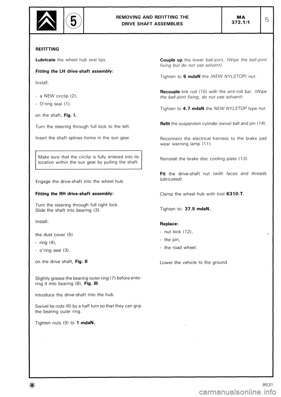
REMOVING AND REFITTING THE
DRIVE SHAFT ASSEMBLIES
REFITTING
Lubricate the wheel hub seal lips.
Fitting the LH drive-shaft assembly:
install:
- a NEW circlip (21,
- O’ring seal (I).
on the shaft, Fig. I.
Turn the steering through full lock to the left.
Insert the shaft splines home in the sun gear.
Make sure that the circlip is fully entered into its
location within the sun gear by pulling the shaft.
Engage the drive-shaft into the wheel hub.
Fitting the RH drive-shaft assembly:
Turn the steering through full right lock.
Slide the shaft into bearing (3).
Install:
the dust cover (5)
- ring (41,
- o’ring seal (3).
on the drive shaft, Fig. II
Slightly grease the bearing outer ring (7) before ente-
ring it into bearing (8). Fig. Ill.
Introduce the drive-shaft into the hub.
Swivel tie rods (6) by a half turn so that they can grip
the bearing outer ring.
Tighten nuts (9) to 1 mdaN. Couple up the lower ball-joint, (Wipe the ball-joint
fixing but do not use solvent).
Tighten to 6 mdaN the (NEW NYLSTOP) nut.
Recouple link rod (IO) with the anti-roll bar. (Wipe
the ball-joint fixing, do not use solvent).
Tighten to 4.7 mdaN the NEW NYLSTOP type nut.
Refit the suspension cylinder swivel ball and pin (14).
Reconnect the electrical harness to the brake pad
wear warning lamp (I I).
Reinstall the brake disc cooling plate (I 3)
Fit the drive-shaft nut (with faces and threads
lubricatedl.
Clamp the wheel hub with tool 6310-T.
Tighten to: 37.5 mdaN.
Replace:
- nut lock (121,
- the pin,
- the road wheel
Lower the vehicle to the ground
3tc 8531
Page 379 of 648
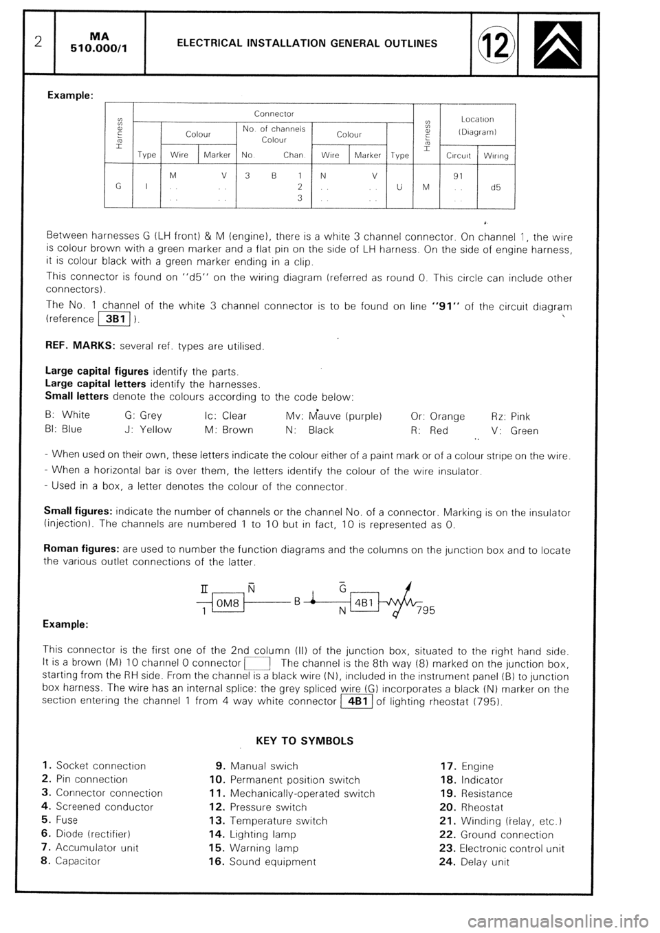
2 51 O%O,l ELECTRICAL INSTALLATION GENERAL OUTLINES
Example:
Connector
cc
t: Locatlori
E
Colour No of channels
Colour a,
(DIagramI
5 Colour :
L
Type Wire 2
Marker No Chan WlrC Marker Type Circuit Wlrlng
M V 3 B 1 N v
91
G I 2 U M d5
3
Between harnesses G (LIH front) & M (engine), there is a white 3 channel connector. On channel 1, the wire
is colour brown with a green marker and a flat pin on the side of LH harness. On the side of engine harness,
it is colour black with a green marker ending in a clip.
This connector is found on “d5” on the wiring diagram (referred as round 0. This circle can include other
connectors).
The No. 1 channel of the white 3 channel connector is to be found on line “91” of the circuit diagram
(reference /3B1/ 1. I
REF. MARKS: several ref. types are utilised.
Large capital figures identify the parts,
Large capital letters identify the harnesses.
Small letters denote the colours according to the code below:
B: White G: Grey Ic: Clear Mv: Gauve (purple) Or: Orange Rr: Pink
BI: Blue J: Yellow M: Brown N: Black R: Red V: Green
1.
- When used on their own, these letters indicate the colour either of a paint mark or of a colour stripe on the wire.
- When a horizontal bar is over them, the letters identify the colour of the wire insulator.
- Used in a box, a letter denotes the colour of the connector.
Small figures: indicate the number of channels or the channel No. of a connector. Marking IS on the insulator
(injection). The channels are numbered 1 to 10 but in fact, 10 is represented as 0.
Roman figures: are used to number the function diagrams and the columns on the junction box and to locate
the various outlet connections of the latter.
$ii-f--B i &Bl/+&-
795
Example:
This connector is the first one of the 2nd column (II) of the junction box, situated to the right hand side.
It is a brown (Ml IO channel 0 connector i-1 The channel is the 8th way (8) marked on the junction box,
starting from the RH side. From the channel is a black wire (N), included in the instrument panel (B) to junction
box harness. The wire has an internal splice: the grey spliced wire (G) incorporates a black (N) marker on the
section entering the channel 1 from 4 way white connector m of lighting rheostat (795).
KEY TO SYMBOLS
1. Socket connection 9. Manual swich 17. Engine
2. Pin connection IO. Permanent position switch 18. Indicator
3. Connector connection 11. Mechanically-operated switch 19. Resistance
4. Screened conductor 12. Pressure switch 20. Rheostat
5. Fuse 13. Temperature switch 21. Winding (ielay, etc.)
6. Diode (rectifier) 14. Lighting lamp 22. Ground connection
7. Accumulator unit 15. Warning lamp 23. Electronic control unit
8. Capacitor 16. Sound equipment 24. Delay unit
Page 382 of 648
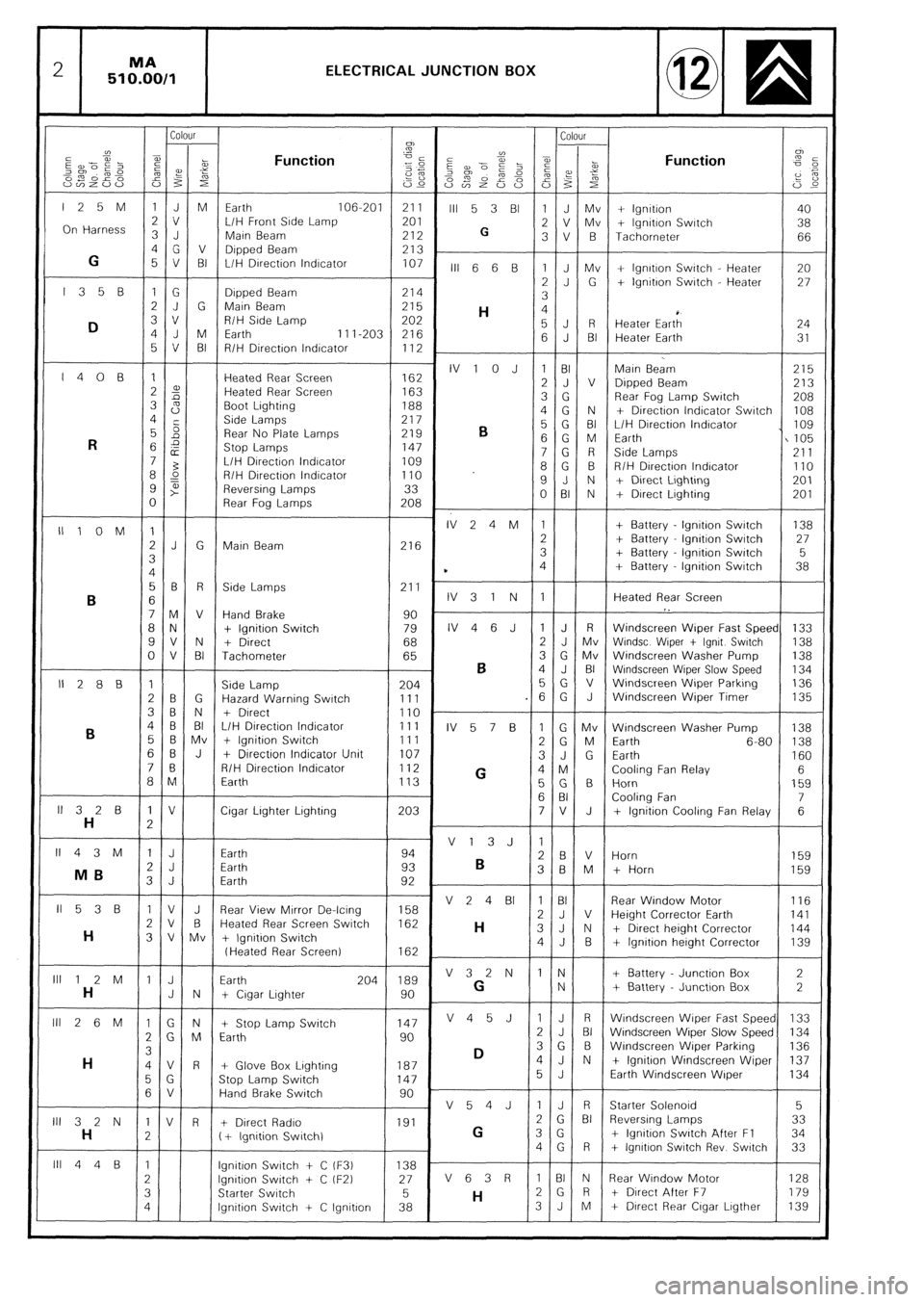
2 MA
510.00/1 ELECTRICAL JUNCTION BOX
Colour Colour
CJ)
”
2
a,
E --Pi- Function ”
i
-1
5 z 2 iz az?i”; cg Function
,%“~o” -0
2% z 2:
om 02’ 2%
Es p 2 f
“v)Z”” i53 s 22
S2r”~S 0% zi ‘i’ F
G,c
125M 1JM Earth 106-201 211
III 5 3 Bl 1 J Mv + lgnttron 40
On Harness 3 J 2 v L/H Front Srde Lamp 201
2 V Mv
G + lgnrtion Swatch 38
Main Beam 212 3V B Tachometer 66
4G V Dipped Beam
G 213
5 V BI L/H Drrectron lndrcator 107
III 6 6 B 1 J Mv + lgnrtron Swatch - Heater 20
l35B 1G 2J G + lgnrtron Switch - Heater 27
Drpped Beam 214
3
2J G Marn Beam 215
H 4
D 3 v R/H Side Lamp 202
4 J M 5J R
Earth Heater Eart; 24
11 I-203 216
5 V BI 6 J BI Heater Earth 31
R/H Direction lndrcator 112
I408 1 Heated Rear Screen IV 1 0 J 1 BI
162 Main Beam 215
2 2 Heated Rear Screen 2 J V
163 Dipped Beam 213
3 s Boot Lighting 3 G
188 Rear Fog Lamp Swatch
208
4 Side Lamps 4G N
217 + Directron Indicator Swatch 108
5 5
Rear No Plate Lamps 219
B 5 G BI L/H Drrection lndrcator I 109
R 6 2
Stop Lamps 6 G M Earth
147 I105
E 7G R Side Lamps
7 3 L/H DIrectron lndrcator 109 211
8 L? R/H Drrectron Indicator 8G B
110 R/H Directron lndrcator 110
9 t” Reversing Lamps 33 9 J N + Direct Lrghtrng 201
0 Rear Fog Lamps 208 0 BI N + Drrect Lrghting 201
IllOM 1 IV24M 1 + Battery lgnttron Switch 138
2J G Marn Beam 216 2 + Battery lgnrtron Swatch 27
3 3 + Battery lgnttion Switch 5
4 * 4 + Battery - lgnitron Swatch 38
56 R Side Lamps 211 .
B 6 IV31N 1 Heated Rear Screen
7M V Hand Brake 90 I.
8 N + Ignition Switch 79 IV46J 1 J R Windscreen Wiper Fast Speed 133
9V N + Direct 68 2 J Mv Wrndsc Wtper t lgnrt Swatch 138
0 V BI Tachometer 65 3 G Mv Windscreen Washer Pump
B 138
4 J BI Wrndscreen Wiper Slow Speed 134
II288 1 Side Lamp 204 5G v Windscreen Wiper Parkrng 136
2 B G Hazard Warning Switch 111 .6 G J Windscreen Wiper Timer 135
3B N + Drrect 110 .
B 4 B BI L/H Direction Indicator 111
IV 5 7 B 1 G Mv Windscreen Washer Pump 138
5 6 Mv + lgnitron Switch 111
2 G M Earth 6-80 138
6B J + Drrection Indicator Unit 107
3J G Earth
7 0 160
R/H Direction Indicator 112
G 4 M Cooling Fan Relay 6 a M Earth 113
5G B Horn 159
6 BI Cooling Fan 7
ll32B 1 V Cigar Lrghter Lighting 203 7V J
H 2 + lgnitron Cooling Fan Relay 6
II43M 1 J V13J 1
Earth 94
2 J 2 B V Horn
Earth 93
B 159
MB 3 B M
3 J Earth + Horn
92 159
II538 1 V J Rear View Mtrror De-lcrng V 2 4 BI 1 BI
158 Rear Window Motor
116
2v B Heated Rear Screen Switch 2J V
162 Height Corrector Earth 141
H H 3 V Mv + Ignition Switch 3J N + Drrect height Corrector 144
4J B + lgnrtron herght Corrector 139
(Heated Rear Screen) 162
lll12M 1 J Earth 204 189 V32N IN + Battery Junction Box 2
H J N + Crgar Lighter 90 G N + Battery Junctron Box 2
Ill 2 6 M 1 G N + Stop Lamp Switch 147 V45J 1 J R Wrndscreen Wrper Fast Speed 133
2 G M Earth 90 2 J BI Windscreen Wiper Slow Speed 134
3
D 3 G B Windscreen Wrper Parking 136
H 4V R + Glove Box Lrghting 187 4J N + lgnitron Windscreen Wiper 137
5 G Stop Lamp Switch 147 5 J Earth Windscreen Wiper 134
6 V Hand Brake Swatch 90
V54J IJ R Starter Solenord 5
III 3 2 N 1 V R + Direct Radro 191 2 G Bi Reversrng Lamps 33
H 2 ( + lgnrtion Swrtchl G 3 G + lgnrtron Swatch After Fl 34
4G R + lgnrtron Swatch Rev Switch 33
lll44B 1 lgnttron Swatch + C iF3) 138 -
2 lgnrtron Switch + C tF2) 27 V 6 3 R 1 BI N Rear Wrndow Motor 128
3 Starter Swatch 5
H 2G R t Direct After F7 179
4 lgnrtion Switch -t C lgnrtron 38 3J M + Dtrect Rear Crgar Lrgther 139
Page 385 of 648
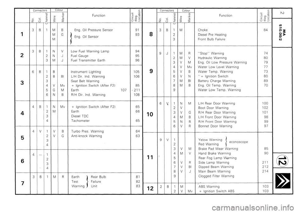
Connectors
l.-~l
a,
- Connectors
,”
9 r, 75 Colour
FiY
E
vl
-
M
M
V
V
V
V
M
M
-
N
v
V
M
N
V
-
V
M
V
V
V
-
M
V
2
$
R
V
M
Mv
B
N
BI
B
Mv . -
z
Y
i
r”
B
G Function Function
:
m
.e-
1
-
1
2
3
-
1
2
3
4
1
2
3
4
I
2
3
4
-
1 .-
f
-
M
M
M
-
N
N
M
-
B
B
V
G
N
-
N
M
-
V
V
-
-
M 1
2
3
-
-
-
-
1
2 -
3 -
6 -
4 -
4 -
4 -
3
1
3
-
9
-
6
-
9
-
2
L.
B
-
J
-
v
-
V
-
B
m
sg
ZD
‘N
B
-
B
-
B
-
B
-
V
-
-
-
B Eng. Oil Pressure Sensor
94
95
96 Choke
Diesel Pre Heating
Front Bulb Failure 84
I 8
1
Eng. Oil Sensor
V
J
J Low Fuel Warning Lamp
Fuel Gauge
Fuel Transmitter Earth “Stop” Warning
Hydraulic Warning
Eng. Oil Low Pressure Warning
Water Low Level Warning
Water Temp. Warning
” + Ignition Switch
Battery Charge Warning
Eng. Oil Temp. Warning
Water Low Temp. Warning
2 74
80
79
77
73
80
89
70
100
102
101
98
99
97
85
90
211
212
214
103
103
9
10
11 Instrument Lighting
L/H Dir. Ind. Warning
Seat Belt Warning
+ Ignition Switch (After F2)
Earth 107
R/H Dir. Ind. Warning 105
106
85
211
108
65
66
65 BI
Mv
M
B
Mv
3
L/H Rear Door Warning
Boot Door Warning
R/H Rear Door Warning
L/H Front Door Warning
R/H Front Door Warning
Bonnet Door Warning + Ignition Switch (After F.2)
Earth
Diesel TDC
Tachometer
4
B
G Turbo Pres. Warning
Anti-knock Warning 64
63
Yelow Warning
Red Warning econoscope
5
Brake Pad Wear Warning
Hand Brake Warning
Rear Fog Lamp Warning
Side Lamp Warning
Dipped Beam Warning
Main Beam Warning
Clogged Filter Warning
0 ic 6
R Earth
Test
Warning Rear Bulb
Failure
Unit 81
82
83
7
12 ?ABS Warning
+ Ignition Switch ABS
Page 388 of 648
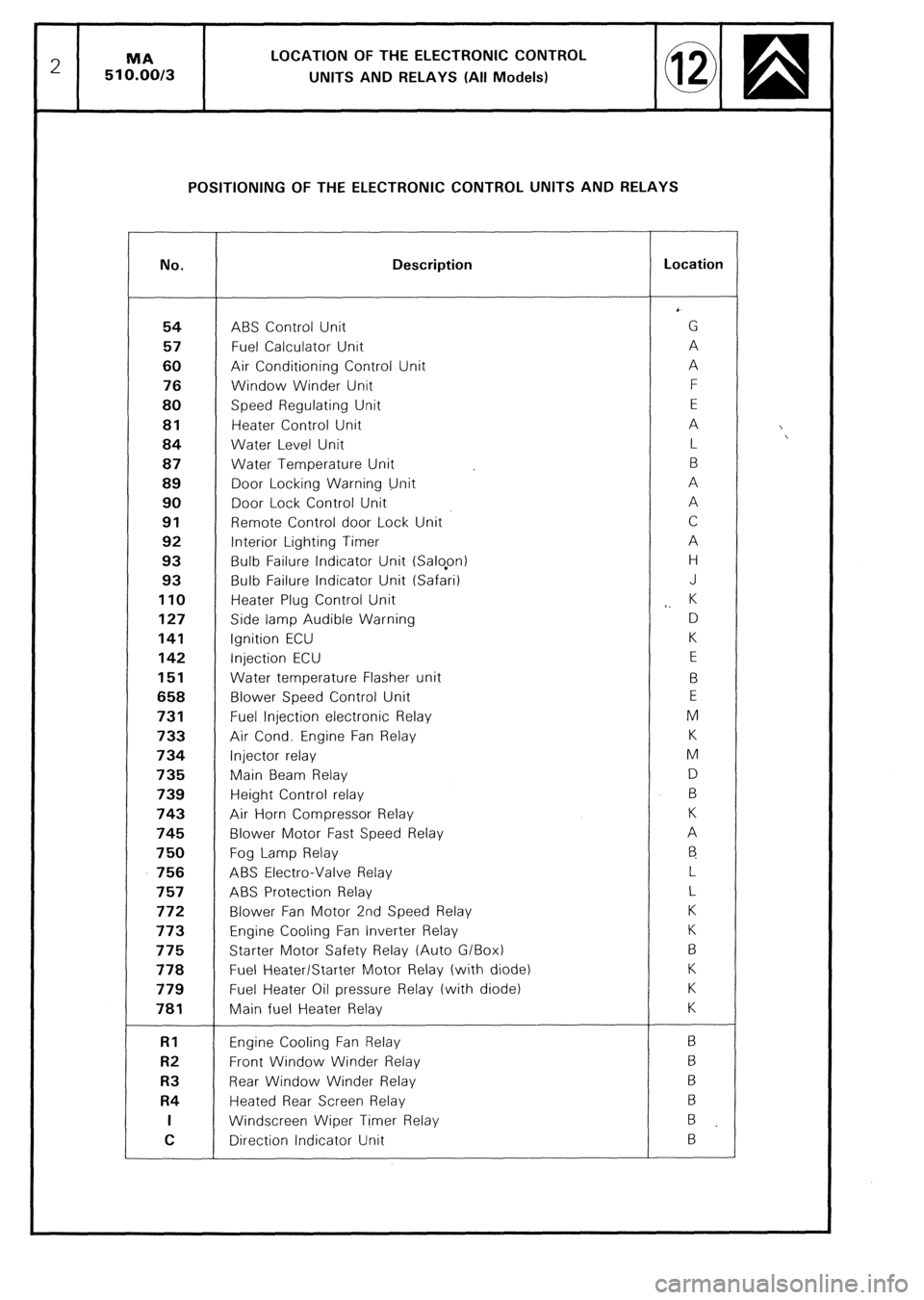
2 MA LOCATION OF THE ELECTRONIC CONTROL
510.00/3
UNITS AND RELAYS (All Models)
POSITIONING OF THE ELECTRONIC CONTROL UNITS AND RELAYS
No. Description Location
54 ABS Control Unit G
57 Fuel Calculator Unit A
60 Air Conditioning Control Unit A
76 Window Winder Unit F
80 Speed Regulating Unit E 81
Heater Control Unit A
84 Water Level Unit L
87 Water Temperature Unit B
89 Door Locking Warning Unit A
90 Door Lock Control Unit A 91
Remote Control door Lock Unit C
92 Interior Lighting Timer A
93 Bulb Failure Indicator Unit (Salopn) H
93 Bulb Failure Indicator Unit (Safari) J 110
Heater Plug Control Unit
,. K 127
Side lamp Audible Warning D 141
Ignition ECU K 142
Injection ECU E 151
Water temperature Flasher unit B 658
Blower Speed Control Unit E 731
Fuel Injection electronic Relay M 733
Air Cond. Engine Fan Relay K 734
Injector relay M 735
Main Beam Relay D
739 Height Control relay B 743
Air Horn Compressor Relay K 745
Blower Motor Fast Speed Relay A 750
Fog Lamp Relay
6 756
ABS Electra-Valve Relay L 757
ABS Protection Relay L 772
Blower Fan Motor 2nd Speed Relay K 773
Engine Cooling Fan lnverter Relay K 775
Starter Motor Safety Relay (Auto G/Box) B 778
Fuel Heater/Starter Motor Relay (with diode) K
779 Fuel Heater Oil pressure Relay (with diode) K 781
Main fuel Heater Relay K RI
Engine Cooling Fan Relay B R2
Front Window Winder Relay 6 R3
Rear Window Winder Relay B R4
Heated Rear Screen Relay 6 I
Windscreen Wiper Timer Relay
B
C Direction Indicator Unit B
Page 392 of 648
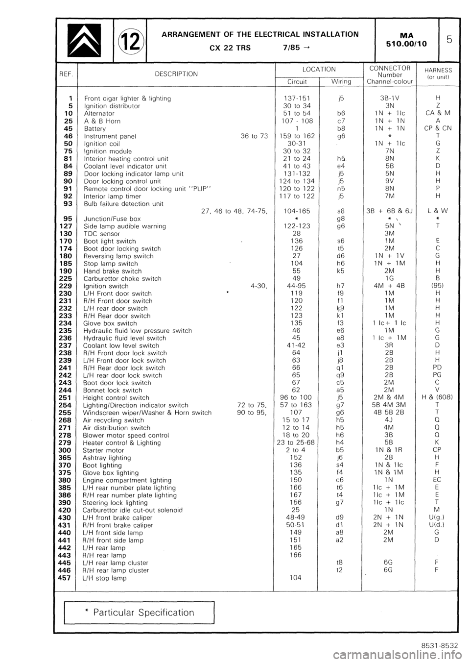
ARRANGEMENT OF THE ELECTRICAL INSTALLATION
q @ CX22TRS 7/85-t 1 MA 5 510.00110
3EF. DESCRIPTION LOCATION
Circuit Wiring CONNECTOR
Number HARNESS
Channel-colour (or urilt)
1 Front cigar ljghter & lighting 137-151
i5 38-l v H
5 Ignition distributor 30 to 34 3N 2
10 Alternator 51 to 54 b6 IN + Ilc CA & M
25 A & B Horn 107 - 108 c7 1N + 1N A
45 Battery 1
b8 IN + IN CP & CN
46 Instrument panel 36 to 73 159 to 162 g6 * T
50 Ignition coil 30-3 1 IN + Ilc G
75 Ignition module 30 to 32 7N Z
81 Interior heating control unit 21 to 24 h5 8N K
84 Coolant level indicator unit 41 to 43 e4 5B D
89 Door locking indicator lamp unit 131-132
i5 5N H
90 Door locking control unit 124 to 134 15 9v H
91 Remote control door locking unit “PLIP” 120 to 122 n5 8N P
92 Interior lamp timer 117 to 122 15 7M H
93 Bulb failure detection unit
27, 46 to 48, 74-75, 104-I 65 S8 38 + 68 & 6J L & w
95 Junction/Fuse box
127 Side lamp audible warning 1222123 g8
g6 5+N‘” ;
130 TDC sensor 28 3M
170 Boot light switch 136 s6 IM E
174 Boot door locking switch 126 t5 2M C
180 Reversing lamp switch 27 d6 1N + 1V G
185 Stop lamp switch 104 h6 IN + IM H
190 Hand brake switch 55 k5 2M H
!25 Carburettor choke switch 49 IG B
!29 Ignition switch 4-30, 44-95 h7 4M + 48 (95)
!30 L/H Front door switch *
119 f9 IM H
!31 R/H Front door switch 120 fl 1M H
!32 L/H rear door switch 122
k9 IM H
!33 R/H Rear door switch 123 kl IM H
!34 Glove box switch 135 f3 1 Ic+ 1 Ic H
!35 Hydraulic fluid low pressure switch 46 e6 IM G
!36 Hydraulic fluid level switch 45 e8 1 Ic + IM G
!37 Coolant low level switch 41-42 e3 3R D
!38 R/H Front door lock switch 64
jl 28 H
!39 L/H Front door lock switch 63 P
28 H
!41 R/H Rear door lock switch 66 (71 28 PD !42 L/H rear door lock switch 65 qg 28 PG
!43 Boot door lock switch 67 c5 2M C
!44 Bonnet lock switch 62 a5 2M V
!51 Height control switch 96 to 100
j5 2M & 4M H & (608) !54 Lighting/Direction indicator switch 72 to 75. 57 to 163 97 58 4M 3M T
!55 Windscreen wiper/Washer & Horn switch 90 to 95, 107 g6 48 5B 28 T
!68 Air recycling switch 15 to 17
h5 4J Q
!71 Air distribution switch 12 to 14 h5 4M Q !78 Blower motor speed control 18 to 20 h6 38 Q
!79 Heater control & Lighting 23 to 25-68 h4 58 K
100 Starter motor 2 to 4 b5 IN & IR CP 165 Ashtray lighting 152 if5 2B H
I70 Boot lighting 136 s4 1N & llc F
I75 Glove box lighting 135 f4 IN & 1M H I80 Engine compartment lighting 150 c6 IN EC
I85 L/H rear number plate lighting 166 t6 Ilc + IM E 186 R/H rear number plate lighting 167 t4 Ilc + IM E
190 Steering lock lighting 156 97 Ilc + IIC T
L20 Carburettor idle cut-out solenoid 25 IN M L30 L/H front brake caliper 48-49 d9 2N + IN U(g.) I31 R/H front brake caliper 50-51 dl 2N + IN U(d.!
L40 L/H front side lamp 149 a8 2M G
141 R/H front side lamp 151 a2 2M D 142 L/H rear lamp 165 L43 R/H rear lamp 166 I45 L/H rear lamp cluster t8 6G F
146 R/H rear lamp cluster t2 6G F
157 L/H stop lamp 104
* Particular Specification
8531-8532
Page 393 of 648
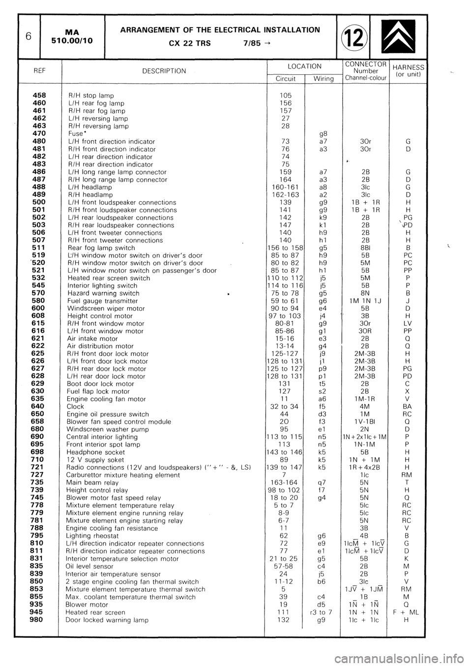
6 ARRANGEMENT OF THE ELECTRICAL INSTALLATION
CX
22 TRS 7185 --)
REF DESCRIPTION LOCATION
“;;;;;roR HARNES:
Circuit Wiring Channel-colour (or unit)
458 R/H stop lamp 105 460 L/H rear fog lamp 156 461 R/H rear fog lamp 157
462 L/H reversing lamp 27
463 R/H reversing lamp 28
470 Fuse l 480 g8 L/H front direction indicator 73 a7 30r G 481 R/H front direction indicator 76 a3 30r D 482 L/H rear direction indicator 74
483 R/H rear direction indicator 75
486 L/H long range lamp connector 159 a7 28 G 487 R/H long range lamp connector 164 a3 2B D 488 L/H headlamp 160-161 a8 3lc G
489 R/H headlamp
162-l 63 a2 3lc D 500 L/H front loudspeaker connections 139
gg IB + IR H 501 R/H front loudspeaker connections 141
gg IB + IR H 502 L/H rear loudspeaker connections 142 k9 28 PG 503 R/H rear loudspeaker connections 147 kl 28 ‘,PD 506 L/H front tweeter connections 140 h9 2B H 507 R/H front tweeter connections 140 hl 28 H
511 Rear fog lamp switch 156 to 158 g5 881 B 519 L/H window motor switch on driver’s door 85 to 87 h9 5B PC ‘520 R/H window motor switch on driver’s door 80 to 82 h9 5M PC 521 L/H window motor switch on passenger’s door 85 to 87 hl 58 PP 532 Heated rear screen switch 110 to 112 j5 5M P 545 Interior lighting switch
114 to 116 j5 58 P 570 Hazard warning switch 75 to 78
g5 8N B 580 Fuel gauge transmitter 59 to 61
96 IM 1N IJ J 600 Windscreen wiper motor 90 to 94 e4 58 D 608 Height control motor 97 to 103 j4 ‘. 38 H 615 R/H front window motor 80-81
gg 30r LV 616 L/H front window motor 85-86
gl 30R PP 621 Air intake motor 15-16 e3 2B Q 622 Air distribution motor 13-14
94 28 0 625 R/H front door lock motor 125-127
0 ZM-3B H 626 L/H front door lock motor 128 to 131 jl ZM-3B H 627 R/H rear door lock motor 125 to 127 p9 2M-3B PG 628 L/H rear door lock motor 128 to 131 pl 2M-3B PD 629 Boot door lock motor 131
t5 2B C 630 Fuel flap lock motor 127 s2 28 X 635 Engine cooling fan motor 11 a6 IM-IR V 640 Clock 32 to 34 f5 4M BA 650 Engine oil pressure switch 44 d3 IM RC 658 Blower fan speed control module 20 f3 1 V-l BI Q 680 Windscreen washer pump 95 el 2N D 690 Central interior lighting 113 to 115 n5 1N+2xllc+lM P 695 Front interior spot lamp 113 n5 lN-1M P 698 Headphone socket 143 to 146 k5 58 H 710 12 V supply soket 89 k5 IN + IM H 721 Radio connections t 12V and loudspeakers) I” + ” - &, LS) 139 to 147 k5 lR+4x2B H 727 Carburettor mixture heating element 7 IIC RM 735 Main beam relay 163-164 q7 5N T 739 Height control relay 98 to 102 f7 5N H 745 Blower motor fast speed relay 18 to 20
94 5N Q 778 Mixture element temperature relay 5 to 7 5lc RC 779 Mixture element engine running relay 8-9 5lc RC 781 Mixture element engine starting relay 6-7 5N RC 788 Engine cooling fan resistance 11 38 V 795 Lighting rheostat 62 g6 4B B 810 L/H direction indicator repeater connectrons 72 e9 II&l + IICT G 811 R/H direction indicator repeater connections 77 el II&l + IICV D 831 Interior temperature selection motor 21 to 25
cl5 5B K 836 Oil level sensor 57-58 c4 28 M 839 Interior air temperature sensor 24
j5 28 P 850
2 stage engine cooling fan thermal switch 11-12
b6 3lc V 853 Mixture element temperature thermal switch 5 IJS + IJti RM 855 Max. coolant temperature thermal switch 39 c4 IB M 935 Blower motor 19 d5 IN + li;j Q 945 Heated rear screen 111 r3 to 7 IN + IN F + ML 980 Door locked warning lamp 132
99 Ilc + Ilc H
Page 399 of 648
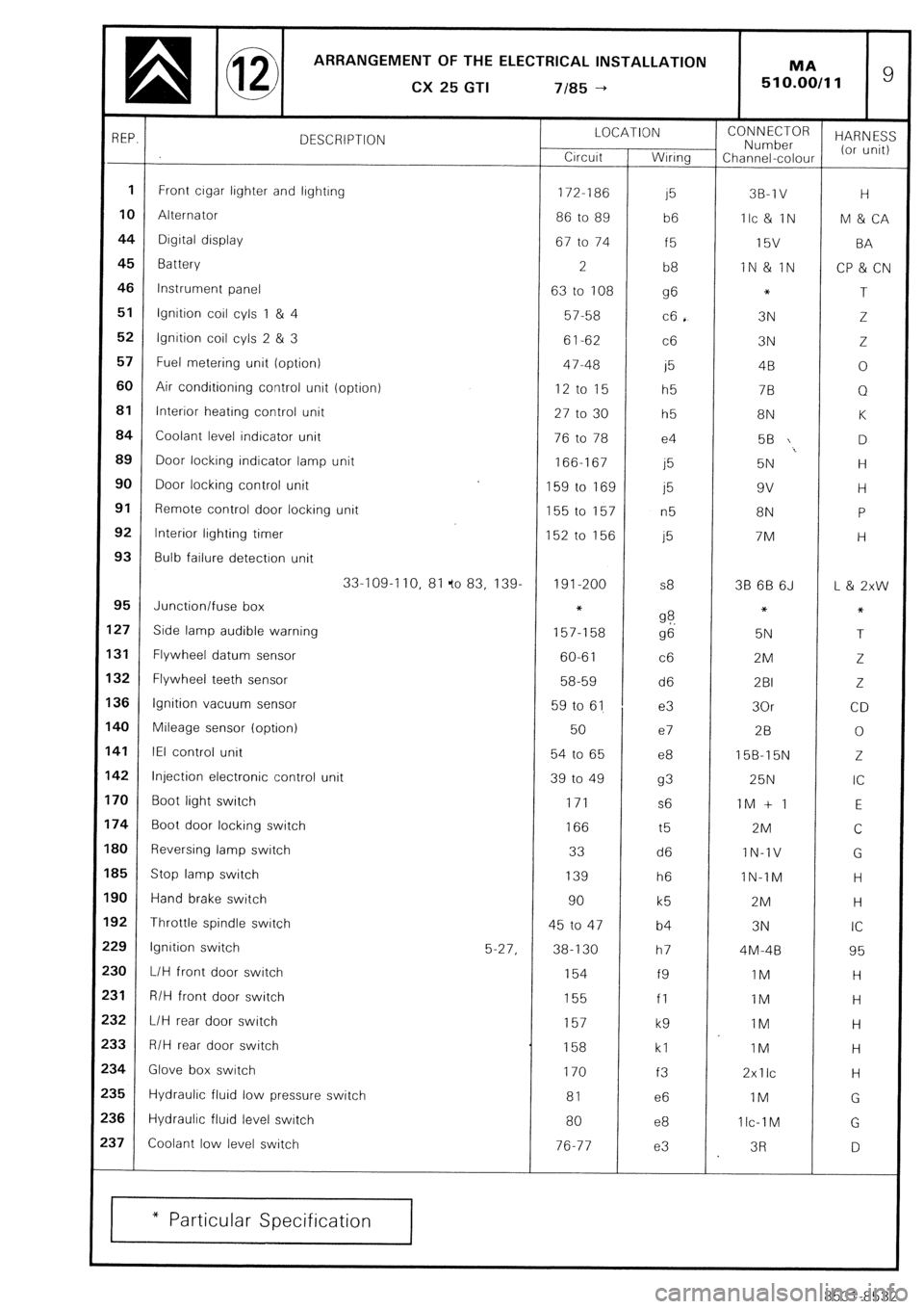
ARRANGEMENT OF THE ELECTRICAL INSTALLATION
a @ CX25GTI 7185-t MA ’ 510.00/11
REP.
DESCRIPTION LOCATION
Crrcurt Wrnng CONNECTOR
Number HARN ES:
Channel-colour (or unit)
1 Front lighter and lrghtrng
crgar 172-186 15 3B-1 V H
10 Alternator
86 to 89
b6 Ilc & IN M & CA
44 Dtgital display
67 to 74 f5 l5V BA
45
Battery
2
b8 IN & IN
CP & CN
46 Instrument panel
63 to 108 g6 *
T
51 Ignition coil cyls 1 & 4
57-58 c6 . 3N Z
52 lgnrtion coil cyls 2 & 3
61-62 c6 3N Z
57 Fuel metering unit (option)
47-48 i5 4B 0
60 Air conditioning control unit (option)
12 to 15
h5 7B Q
81 Interior heating control unit
27 to 30 h5 8N K
84 Coolant level indicator unit
76 to 78 e4 56 D
89
Door locking indicator lamp unit
166-167
j5 5N H
90 Door locking control unit
159 to 169 j5 9v H
91
Remote control door locking unit
155 to 157
n5 8N P
92 Interior lighting timer
152 to 156 j5 7M H
93 Bulb failure detectron unit
33-109-I 10, 81 fo 83, 139. 191-200 s8 38 6B 6J L & 2xw
95 Junction/fuse box *
27 Side lamp audible warning 9 ?. *
*
157-l 58
g6 5N T
31
Flywheel datum sensor
60-61 c6 2M
Z
32 Flywheel teeth sensor
58-59 d6 2BI 2.
36 Ignition vacuum sensor
59 to 61 e3 30r CD
40 Mileage sensor (option)
50 e7 28 0
41 IEI control unit
54 to 65 e8 15B-15N Z
42 Injection electronic control unit
39 to 49 93 25N IC
70 Boot light switch
171 s6 1M + 1 E
74
Boot door locking switch
166 t5 2M
C
BO
Reversing lamp switch 33
d6 IN-1V
G
B5 Stop lamp switch
139 h6 IN-TM H
90 Hand brake switch
90
k5 2M H
92 Throttle spindle switch
45 to 47 b4 3N IC
29 lgnrtion switch
5-27, 38-130 h7 4M-48 95
30
L/H front door switch 154
f9 IM H
31 R/H front door switch
155
fl IM H
32 L/H rear door switch
157
k9 IM H
33 R/H rear door switch
158 kl 1M H
34
Glove box switch
170
f3 2xllc
H
35 Hydraulic fluid low pressure switch
81 e6 IM
G
$6
Hydraulic fluid level swatch
80 e8 1 Ic-1 M
G
$7
Coolant low level switch
76-77 e3 3R
D
* Particular Specification
8531-8532