ECU CITROEN DISPATCH SPACETOURER DAG 2021 Handbook (in English)
[x] Cancel search | Manufacturer: CITROEN, Model Year: 2021, Model line: DISPATCH SPACETOURER DAG, Model: CITROEN DISPATCH SPACETOURER DAG 2021Pages: 324, PDF Size: 10.52 MB
Page 192 of 324

190
Practical information
Roof bars/Roof rack
As a safety measure and to avoid damaging the roof, it is essential to use
the roof bars and roof racks approved for your
vehicle.
Observe the instructions on fitting and use
contained in the guide supplied with the roof
bars and racks.
Recommendations
Distribute the load uniformly, taking care
to avoid overloading one of the sides.
Arrange the heaviest part of the load as close
as possible to the roof.
Secure the load firmly.
Drive gently: the vehicle will be more
susceptible to the effects of side winds and its
stability may be affected.
Regularly check the security and tight
fastening of the roof bars, at least before each
trip.
Remove the roof bars once they are no longer
needed.
As this value may change, please verify the maximum load quoted in the guide
supplied with the roof bars.
If the height exceeds 40 cm, adapt the speed
of the vehicle to the profile of the road to
avoid damaging the roof bars and the fixings
on the vehicle.
Snow chains
In wintry conditions, snow chains improve
traction as well as the behaviour of the vehicle
when braking.
Snow chains must be fitted only to the
front wheels. They must never be fitted to
"space-saver" type spare wheels.
Observe the legislation in force in your
country relating to the use of snow
chains and maximum authorised speeds.
Only use chains that have been designed for the
type of wheel fitted to your vehicle.
Original tyre size Type of chain 215/65 R16 12
mm link
215/60 R17 KONIG K-SUMMIT VAN K84
225/55 R17
You can also use snow socks.
For more information, contact a CITROËN dealer
or a qualified workshop.
Installation tips
► To fit the snow chains during a journey, stop
the vehicle on a flat surface at the side of the
road.
►
Apply the parking brake and position any
wheel chocks under the wheels to prevent
movement of the vehicle.
► Fit the snow chains following the instructions
provided by the manufacturer .
►
Move off gently and drive for a few moments,
without exceeding 31
mph (50 km/h).
►
Stop the vehicle and check that the snow
chains are correctly tightened.
It is strongly recommended that you
practise fitting the snow chains on a level
and dry surface before setting off.
Avoid driving with snow chains on roads that have been cleared of snow to avoid
damaging the vehicle's tyres and the road
surface. If the vehicle is fitted with alloy
wheels, check that no part of the chain or its
fixings is in contact with the wheel rim.
Towing device
Load distribution
► Distribute the load in the trailer so that the
heaviest items are as close as possible to the
axle, and the nose weight approaches the
maximum permitted without exceeding it.
Air density decreases with altitude, thus reducing
engine performance.
The maximum towable load
must be reduced by 10% per 1,000
metres of
altitude.
Use genuine towing devices and wiring
harnesses approved by CITROËN. We
recommend having them fitted by a CITROËN
dealer or a qualified workshop.
If not fitted by a CITROËN dealer, they must
still be fitted in accordance with the vehicle
manufacturer's instructions.
Certain driving or manoeuvring aid functions
are automatically deactivated while an
approved towing system is in use.
Comply with the maximum authorised
towable weight, as indicated on your
vehicle's registration certificate, on the
manufacturer's label and in the Technical
data section of this guide.
Complying with the maximum authorised
nose weight (towball weight) also includes
the use of accessories (bicycle carriers,
tow boxes, etc.).
Observe the legislation in force in the
country where you are driving.
Electric motor
An electric vehicle may be fitted with a
towing device.
It is therefore possible to tow a trailer or
caravan.
Contact a CITROËN dealer or qualified
workshop for more information and to obtain a
suitable towing device.
Page 193 of 324

191
Practical information
7Roof bars/Roof rack
As a safety measure and to avoid damaging the roof, it is essential to use
the roof bars and roof racks approved for your
vehicle.
Observe the instructions on fitting and use
contained in the guide supplied with the roof
bars and racks.
Recommendations
Distribute the load uniformly, taking care
to avoid overloading one of the sides.
Arrange the heaviest part of the load as close
as possible to the roof.
Secure the load firmly.
Drive gently: the vehicle will be more
susceptible to the effects of side winds and its
stability may be affected.
Regularly check the security and tight
fastening of the roof bars, at least before each
trip.
Remove the roof bars once they are no longer
needed.
As this value may change, please verify the maximum load quoted in the guide
supplied with the roof bars.
If the height exceeds 40 cm, adapt the speed
of the vehicle to the profile of the road to
avoid damaging the roof bars and the fixings
on the vehicle.
Be sure to refer to national legislation in order
to comply with the regulations for transporting
objects that are longer than the vehicle.
Roof bars
A maximum of 3 roof bars (or 2 bars for the
version with panoramic sunroof) can be installed
- use the positions marked in green.
With panoramic sunroof
Max. authorised load weight:
– over 2 roof bars: 100 kg,
–
distributed over 3 roof bars: 150
kg.
To install the transverse roof bars, use the fixing
points provided for this purpose:
►
Open the fixing covers on each bar
.
►
Put each fixing point in place and lock them
to the roof one by one.
►
Ensure that the roof bars are correctly fitted
(by shaking them).
►
Close the fixing covers on each bar
.
The bars can be interchanged and are adaptable
to each pair of fixing points.
Roof racks
Max. authorised load weight:
– XS: 140 kg,
–
M and XL: 170 kg.
T
o fit a roof rack, use the fixing points provided
for this purpose:
Page 194 of 324

192
Practical information
Diesel engine
1.Screenwash fluid reservoir
2. Engine coolant reservoir
3. Brake fluid reservoir
4. Battery
5. Remote earth point (-)
6. Fusebox
7. Air filter
8. Engine oil filler cap
9. Engine oil dipstick
10. Priming pump*
11 . Power steering fluid reservoir
Diesel fuel system
This system is under very high pressure.
All work must be carried out only by a
CITROËN dealer or a qualified workshop.
* Depending on engine.
► Place the roof rack on the roof aligned with
the fixing points and secure each one to the roof
in turn.
►
Ensure that the roof rack is correctly fitted (by
shaking it).
Bonnet
Stop & Start
Before doing anything under the bonnet,
you must switch off the ignition to avoid any
risk of injury resulting from an automatic
change to START mode.
Electric motor
Take care with objects or clothing that
could be caught in the blades of the cooling
fan or in certain moving components - risk of
strangulation and serious injury!
Before carrying out any work under the
bonnet, you must switch off the ignition, check
that the READY indicator lamp is off on the
instrument panel and disconnect the charging
nozzle if it is plugged in.
The location of the interior bonnet release lever prevents the bonnet being
opened when the left-hand front door is
closed.
When the engine is hot, handle the
exterior safety catch and the bonnet stay
with care (risk of burns), using the protected
area.
When the bonnet is open, take care not to
damage the safety catch.
Do not open the bonnet under very windy
conditions.
Cooling of the engine when stopped
The engine cooling fan may start after
the engine has been switched off.
Take care with objects or clothing that
could be caught in the blades of the fan!
Opening
► Open the door .
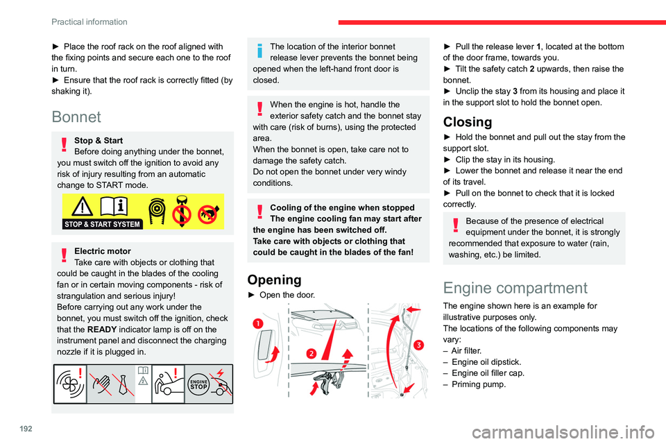
► Pull the release lever 1 , located at the bottom
of the door frame, towards you.
►
T
ilt the safety catch 2 upwards, then raise the
bonnet.
►
Unclip the stay
3 from its housing and place it
in the support slot to hold the bonnet open.
Closing
► Hold the bonnet and pull out the stay from the
support slot.
►
Clip the stay in its housing.
►
Lower the bonnet and release it near the end
of its travel.
►
Pull on the bonnet to check that it is locked
correctly
.
Because of the presence of electrical
equipment under the bonnet, it is strongly
recommended that exposure to water (rain,
washing, etc.) be limited.
Engine compartment
The engine shown here is an example for
illustrative purposes only.
The locations of the following components may
vary:
–
Air filter
.
–
Engine oil dipstick.
–
Engine oil filler cap.
–
Priming pump.
Page 206 of 324

204
In the event of a breakdown
► Once the box is fully home in its housing,
push it against the floor carpet then slide latches
A outwards to secure it.
Pull on the box to check that it is secure
in its housing.
Temporary puncture repair kit
Scan the QR Code on page 3 to view
explanatory videos.
Made up of a compressor and a sealant
cartridge, it allows you to carry out a temporary
repair of the tyre so that you can drive to the
nearest garage.
It is designed to repair most punctures located
on the tyre tread.
Its compressor can be used to check and
adjust the pressure of the tyre.
Tool box
Access
The tool box is located under the left-hand front
seat.
As a safety measure, bars 1 and 2 prevent the box escaping from its
housing, if it is not correctly secured.
Removing
► Press latches A and slide them inwards to
release the box.
►
T
o take it past bar 1, raise the box slightly
then pull it as far as it will go.
► Then, lift the box upwards to take it past bar
2 .
Opening
► Unclip fixings B on the cover, then open it for
access to the tools.
Storage
► Refit the cover on the box and clip fixings B .
► Position the box with the front inclined
upwards.
►
T
o take it past bar 2, push the box in and
down.
►
T
o take it past bar 1, raise the box slightly
then push it fully in.
Page 207 of 324

205
In the event of a breakdown
8
► Once the box is fully home in its housing,
push it against the floor carpet then slide latches
A outwards to secure it.
Pull on the box to check that it is secure
in its housing.
Temporary puncture repair kit
Scan the QR Code on page 3 to view
explanatory videos.
Made up of a compressor and a sealant
cartridge,
it allows you to carry out a temporary
repair of the tyre so that you can drive to the
nearest garage.
It is designed to repair most punctures located
on the tyre tread.
Its compressor can be used to check and
adjust the pressure of the tyre.
Access to the kit
This kit is stowed in a tool box.
For more information on the Tool box,
refer to the corresponding section.
List of tools
These tools are specific to the vehicle and may
vary according to the level of equipment. Do not
use them for any other purpose.
1. 12 V compressor.
Contains a sealant cartridge for the
temporary repair of a tyre and can also be
used for adjusting tyre pressures.
2. Towing eye.
For more information on Towing, please
refer to the corresponding section.
Tyre inflation pressures are indicated on this label.
For more information on Identification
markings, particularly this label, refer to the
corresponding section.
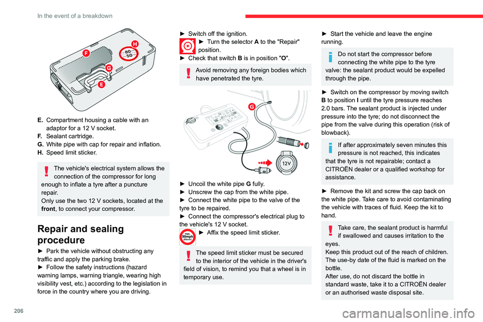
Composition of the kit
A. "Repair" or "Inflation" position selector.
B. On I/off O switch.
C. Deflation button.
D. Pressure gauge (in bars and psi).
Page 208 of 324

206
In the event of a breakdown
E.Compartment housing a cable with an
adaptor for a 12
V socket.
F. Sealant cartridge.
G. White pipe with cap for repair and inflation.
H. Speed limit sticker.
The vehicle's electrical system allows the
connection of the compressor for long
enough to inflate a tyre after a puncture
repair.
Only use the two 12 V sockets, located at the
front, to connect your compressor.
Repair and sealing
procedure
► Park the vehicle without obstructing any
traffic and apply the parking brake.
►
Follow the safety instructions (hazard
warning lamps, warning triangle, wearing high
visibility vest, etc.) according to the legislation in
force in the country where you are driving.
► Switch off the ignition.► Turn the selector A to the "Repair"
position.
►
Check that switch
B is in position " O".
Avoid removing any foreign bodies which
have penetrated the tyre.
► Uncoil the white pipe G fully.
► Unscrew the cap from the white pipe.
►
Connect the white pipe to the valve of the
tyre to be repaired.
►
Connect the compressor's electrical plug to
the vehicle's 12 V socket.
► Affix the speed li mit sticker.
The speed limit sticker must be secured
to the interior of the vehicle in the driver's
field of vision, to remind you that a wheel is in
temporary use.
► Start the vehicle and leave the engine
running.
Do not start the compressor before
connecting the white pipe to the tyre
valve: the sealant product would be expelled
through the pipe.
►
Switch on the compressor by moving switch
B
to position I until the tyre pressure reaches
2.0 bars. The sealant product is injected under
pressure into the tyre; do not disconnect the
pipe from the valve during this operation (risk of
blowback).
If after approximately seven minutes this
pressure is not reached, this indicates
that the tyre is not repairable; contact a
CITROËN dealer or a qualified workshop for
assistance.
►
Remove the kit and screw the cap back on
the white pipe.
Take care to avoid contaminating
the vehicle with traces of fluid. Keep the kit to
hand.
Take care, the sealant product is harmful if swallowed and causes irritation to the
eyes.
Keep this product out of the reach of children.
The use-by date of the fluid is marked on the
bottle.
After use, do not discard the bottle in
standard waste, take it to a CITROËN dealer
or an authorised waste disposal site.
Page 212 of 324

210
In the event of a breakdown
► Engage the carrier on the hook, then tighten
the bolt using the wheelbrace until the bolt is fully
tightened.
Tyre in the carrier
You can change the size of the tyre on the spare
wheel by following the instructions below.
Original tyre
size XS-M
XL
215/65 R16 Placing a 225 wheel in the carrier is prohibited. There is no
restriction.
215/60 R17
215/60 R17
M&S
225/55 R17 Placing a 215 wheel in the carrier is not recom-
mended (risk of noise).
A punctured tyre of size 215 or 225 can be placed in the carrier.
Removing a wheel
Parking the vehicle
Immobilise the vehicle where it does
not obstruct traffic: the ground must be level,
stable and non-slippery.
With a manual gearbox, engage first gear
then switch off the ignition to block the
wheels.
With an automatic gearbox, place the gear
selector in position P then switch off the
ignition to block the wheels.
With a drive selector, place the gear selector
in position P then switch off the ignition to
block the wheels.
Apply the parking brake, unless it is
programmed to automatic mode (for an
electric parking brake), and check that the
indicator lamp lights up on
the instrument
panel.
Ensure that the occupants have left the
vehicle and are located in a safe place.
Never go underneath a vehicle raised using a
jack; use an axle stand.
With an electric parking brake, place a chock
against the wheel diagonally opposite to the
one being replaced.
► With a steel wheel, remove the bolt cover
using tool 3
or the wheel trim by hand. ►
With an alloy wheel, remove the cover from
each of the bolts using tool 3
.
►
If the vehicle is so equipped, fit security bolt
socket
4 to wheelbrace
1 to slacken the security
bolt.
►
Slacken
(without removing) the other wheel
bolts using just wheelbrace 1.
► Place the foot of the jack on the ground and
ensure that it is directly below the A
or B jacking
point provided on the underbody, whichever is
closest to the wheel to be changed.
Page 218 of 324

216
In the event of a breakdown
Platform cab (rear lamps)
1.Direction indicators (P21W-21W).
2. Brake lamps (P21W-21W).
3. Sidelamps (R10W-10W).
4. Reversing lamps (P21W-21W).
5. Foglamps (P21W-21W).
► Locate the faulty bulb.
► Unscrew the 4 fixing screws from the lens
unit and remove it.
► Remove the faulty bulb by pressing lightly on
it, then turning it a quarter turn clockwise.
► Change the bulb.
► With side-hinged doors, remove the plastic
cover with the aid of a screwdriver .
►
With a tailgate, unclip the trim at each end,
rotating it from bottom to top, then unclip the
centre clips to remove it.
►
Using a screwdriver through the aperture,
push the lamp towards the outside.
►
Disconnect the electrical connector and then
remove the lamp.
►
Unscrew the bulb holder a quarter turn anti-
clockwise and replace the faulty bulb.
T
o refit, press on the lamp to clip it into place.
Number plate lamps (W5W-W)
► Insert a thin screwdriver into one of the cut-
outs on the exterior of the lens.
►
Push it outwards to unclip it.
►
Remove the lens and replace the faulty bulb.
T
o refit, press the lens to clip it in.
Courtesy lamps (front and
rear)
LED courtesy lamps
For the replacement of these bulbs, contact a
CITROËN dealer or a qualified workshop.
A replacement kit for the LEDs is available from
CITROËN dealers.
Courtesy lamps with bulb
W5W-5W
► Unclip the lens by inserting a thin screwdriver
into the slots at each side of the courtesy lamp.
►
Remove the bulb and change it.
T
o refit, clip the lens in place and ensure that it
is secure.
Page 219 of 324

217
In the event of a breakdown
8Platform cab (rear lamps)
1.Direction indicators (P21W-21W).
2. Brake lamps (P21W-21W).
3. Sidelamps (R10W-10W).
4. Reversing lamps (P21W-21W).
5. Foglamps (P21W-21W).
►
Locate the faulty bulb.
►
Unscrew the 4 fixing screws from the lens
unit and remove it.
►
Remove the faulty bulb by pressing lightly on
it, then turning it a quarter turn clockwise.
►
Change the bulb.
Changing a fuse
Access to tools and to the dashboard fusebox
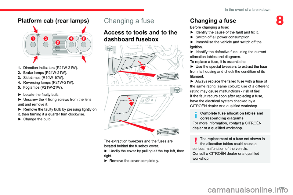
The extraction tweezers and the fuses are
located behind the fusebox cover.
►
Unclip the cover by pulling at the top left, then
right.
►
Remove the cover completely
.
Changing a fuse
Before changing a fuse:
► Identify the cause of the fault and fix it.
►
Switch off all power consumption.
►
Immobilise the vehicle and switch off the
ignition.
►
Identify the defective fuse using the current
allocation tables and diagrams.
T
o replace a fuse, it is essential to:
►
Use the special tweezers to extract the fuse
from its housing and check the condition of its
filament.
►
Always replace the failed fuse with a fuse of
the same rating (same colour); use of a different
rating may cause malfunctions - risk of fire!
If the fault recurs soon after replacing a fuse,
have the electrical system checked by a
CITROËN dealer or a qualified workshop.
Complete fuse allocation tables and
corresponding diagrams
For more information, contact a CITROËN
dealer or a qualified workshop.
The replacement of a fuse not shown in the allocation tables could cause a
serious malfunction of the vehicle.
Consult a CITROËN dealer or a qualified
workshop.
Page 222 of 324

220
In the event of a breakdown
the booster (or to an earth point on the assisting
vehicle).
► Connect the other end of the green or black
cable to the earth point C.
► Start the engine on the assisting vehicle and
leave it running for a few minutes.
► Operate the starter on the broken down
vehicle and let the engine run.
If the engine does not start immediately, switch
off the ignition and wait a few moments before
trying again.
► Wait for it to return to idle.
► Disconnect the jump leads in reverse order.
► Refit the plastic cover to the (+) terminal, if
the vehicle has one.
► Allow the engine to run for at least
30 minutes, with the vehicle stationary, so that
the battery reaches an adequate state of charge.
Driving immediately without having
reached a sufficient level of charge may
affect some of the vehicle's functionalities.
To disconnect, proceed in reverse order.
Automatic gearbox
Never try to start the engine by pushing
the vehicle.
Electric motor
Flat accessory battery
It is no longer possible to start the motor
or recharge the traction battery.
Precautions before working on the
accessory battery
Select mode
P, switch off the ignition, check
that the instrument panel is off and that the
vehicle is not plugged in.
Jump-starting another vehicle
Do not use the accessory battery to
jump-start another vehicle or to charge
another vehicle's battery.
Always replace the battery with one of equivalent specification.
Access to the battery
The battery is located under the bonnet.
► Open the bonnet using the interior release
lever
, then the exterior safety catch.
►
Secure the bonnet stay
.
► Remove the plastic cover to access the (+)
terminal, if your vehicle has one.
The battery (-) terminal is not accessible.
A
remote earth point is provided at the front of
the vehicle.
For more information on the Bonnet and
the Engine , refer to the corresponding
sections.
Starting using another
battery
If the vehicle's battery is flat, the engine can be
started using a backup battery (either external or
from another vehicle) and jump leads or using a
battery booster.
Never start the engine by connecting a
battery charger.
Never use a 24
V or higher battery booster.
Check beforehand that the backup battery
has a nominal voltage of 12
V and a capacity
at least equal to that of the discharged
battery.
The two vehicles must not be in contact with
each other.
Switch off all electricity-consuming equipment
on both vehicles (audio system, wipers,
lighting, etc.).
Make sure that the jump leads are well away
from the engine’s moving parts (fan, belt,
etc.).
Do not disconnect the (+) terminal while the
engine is running.
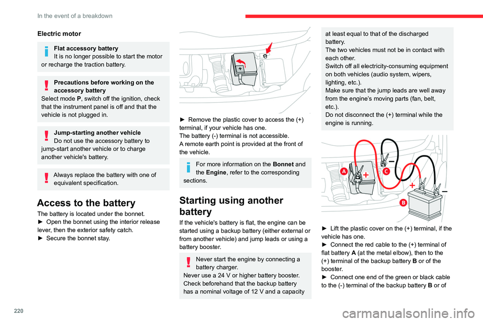
► Lift the plastic cover on the (+) terminal, if the
vehicle has one.
►
Connect the red cable to the (+) terminal of
flat battery
A (at the metal elbow), then to the
(+) terminal of the backup battery
B or of the
booster.
►
Connect one end of the green or black cable
to the (-) terminal of the backup battery
B or of