CITROEN DS3 CABRIO DAG 2017 Handbook (in English)
Manufacturer: CITROEN, Model Year: 2017, Model line: DS3 CABRIO DAG, Model: CITROEN DS3 CABRIO DAG 2017Pages: 444, PDF Size: 14.09 MB
Page 201 of 444
199
DS3_en_Chap08_info-pratiques_ed02-2015
The speed limit st icker mu st be se cured to t
he interior of the vehicle in the
driver's
f
ield
o
f
v
ision,
t
o
r
emind
y
ou
th
at
a w
heel
i
s
i
n
t
emporary
u
se.
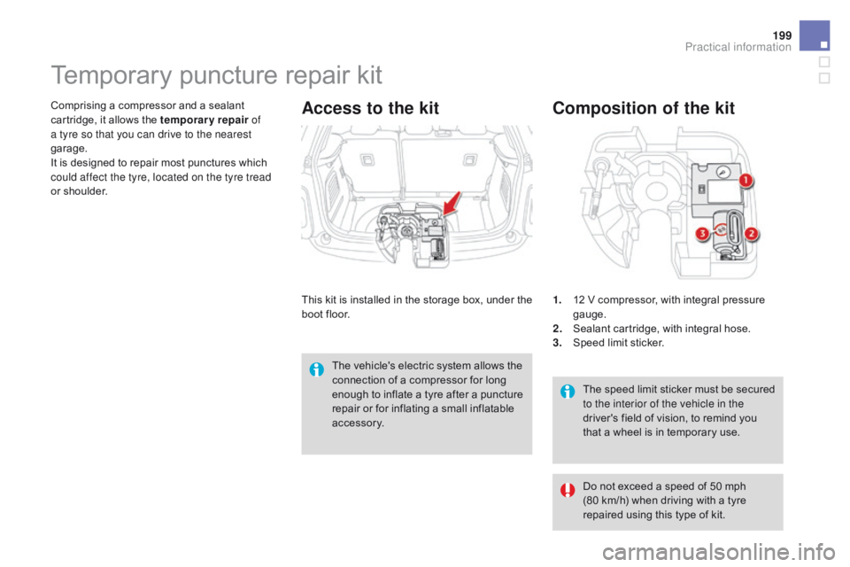
Composition of the kit
1. 12 V compressor, with i ntegral p ressure gaug
e.
2.
Se
alant
c
artridge,
w
ith
i
ntegral
h
ose.
3.
Sp
eed
l
imit
s
ticker.
Temporary puncture re pair kit
Comprising a compressor and a sealant ca
rtridge, i t a llows t he t emporary repair of
a tyre so that you can drive to the nearest
garage.
It
i
s
d
esigned
t
o
r
epair
m
ost
p
unctures
w
hich
co
uld affect the tyre, located on the tyre tread
or
s
houlder.Access to the kit
This kit is installed in th e st orage bo x, un der th e bo
ot f loor.
The
v
ehicle's
e
lectric
s
ystem
a
llows
t
he
co
nnection
o
f
a c
ompressor
f
or
l
ong
en
ough
t
o
i
nflate
a t
yre
a
fter
a p
uncture
re
pair
o
r
f
or
i
nflating
a s
mall
i
nflatable
ac
cessory. Do
n
ot
e
xceed
a s
peed
o
f
5
0
m
ph
(
80
k
m/h)
w
hen
d
riving
w
ith
a t
yre
re
paired
u
sing
t
his
t
ype
o
f
k
it.
Practical information
Page 202 of 444
DS3_en_Chap08_info-pratiques_ed02-2015
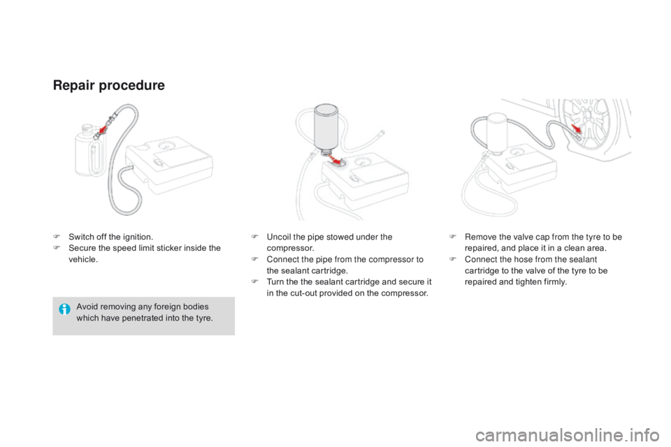
F Switch off t he i gnition.
F Se cure t he s peed l imit s ticker i nside t he ve
hicle.
Repair procedure
Avoid removing any foreign bodies which h ave p enetrated i nto t he t yre.F
Un
coil the pipe stowed under the
compressor.
F
Co
nnect the pipe from the compressor to
the
s
ealant
c
artridge.
F
Tu
rn
t
he
t
he
s
ealant
c
artridge
a
nd
s
ecure
i
t
in t
he
c
ut-out
p
rovided
o
n
t
he
c
ompressor.F
Re
move the valve cap from the tyre to be
repaired,
a
nd
p
lace
i
t
i
n
a c
lean
a
rea.
F
Co
nnect the hose from the sealant
cartridge
t
o
t
he
v
alve
o
f
t
he
t
yre
t
o
b
e
re
paired
a
nd
t
ighten
f
irmly.
Page 203 of 444
201
DS3_en_Chap08_info-pratiques_ed02-2015
If after around 5 to 7 minutes the
pressure is not attained, this indicates
that
t
he
t
yre
i
s
n
ot
r
epairable;
c
ontact
a CI
TROËN dealer or a qualified
workshop
f
or
a
ssistance.
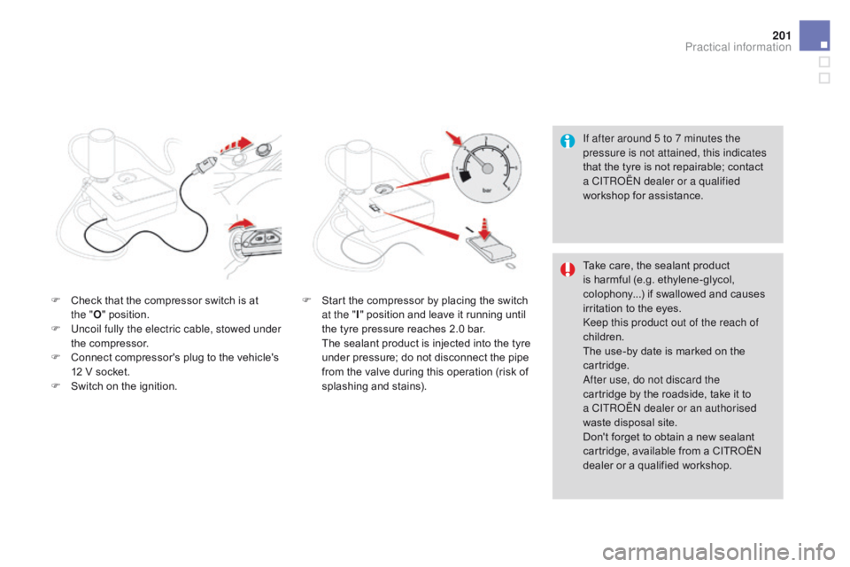
F
Ch
eck
t
hat
t
he
c
ompressor
s
witch
i
s
a
t
th
e
" O " p
osition.
F
Un
coil fully the electric cable, stowed under
the
c
ompressor.
F
Co
nnect
c
ompressor's
p
lug
t
o
t
he
v
ehicle's
12 V s
ocket.
F
Sw
itch
o
n
t
he
i
gnition. F
St
art
t
he
c
ompressor
b
y
p
lacing
t
he
s
witch
at t
he " I"
p
osition
a
nd
l
eave
i
t
r
unning
u
ntil
th
e
t
yre
p
ressure
r
eaches
2
.0
b
ar.
Th
e
s
ealant
p
roduct
i
s
i
njected
i
nto
t
he
t
yre
un
der
p
ressure;
d
o
n
ot
d
isconnect
t
he
p
ipe
fr
om
t
he
v
alve
d
uring
t
his
o
peration
(
risk
o
f
spla
shing
and st
ains). Take
c
are,
t
he
s
ealant
p
roduct
is h
armful
(
e.g.
e
thylene-glycol,
co
lophony...)
i
f
s
wallowed
a
nd
c
auses
ir
ritation
t
o
t
he
e
yes.
Keep this product out of the reach of
children.
The
u
se-by
d
ate
i
s
m
arked
o
n
t
he
ca
rtridge.
After use, do not discard the
cartridge
b
y
t
he
r
oadside,
t
ake
i
t
t
o
a CI
TROËN
d
ealer or an authorised
waste
d
isposal
s
ite.
Don't
f
orget
t
o
o
btain
a n
ew
s
ealant
ca
rtridge,
a
vailable
f
rom
a C
ITROËN
de
aler
o
r
a q
ualified
w
orkshop.
Practical information
Page 204 of 444
DS3_en_Chap08_info-pratiques_ed02-2015
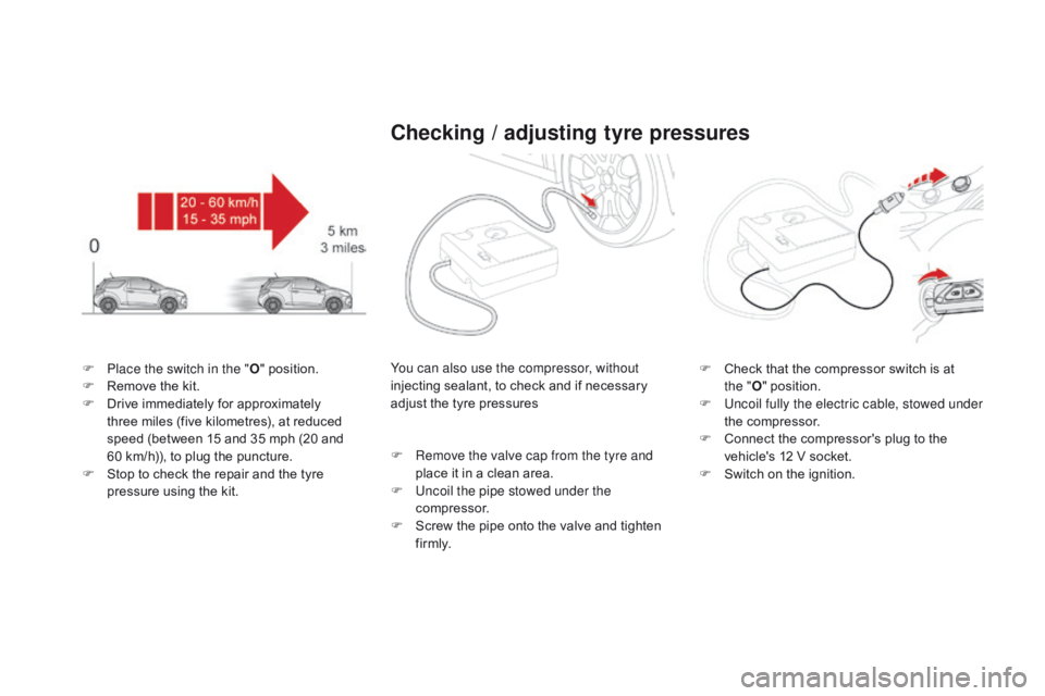
F Place the switch in the "O" p osition.
F Re move t he k it.
F
Dr
ive
i
mmediately
f
or
a
pproximately
th
ree
m
iles
(
five
k
ilometres),
a
t
r
educed
sp
eed
(
between
1
5
a
nd
3
5
m
ph
(
20
a
nd
60 k
m/h)),
t
o
p
lug
t
he
p
uncture.
F
St
op
t
o
c
heck
t
he
r
epair
a
nd
t
he
t
yre
pr
essure
u
sing
t
he
k
it.
Checking / adjusting tyre pressures
You can also use the compressor, without
injecting sealant, t o c heck a nd i f n ecessary ad
just
t
he
t
yre
p
ressures
F
Re
move the valve cap from the tyre and
place
i
t
i
n
a c
lean
a
rea.
F
Un
coil the pipe stowed under the
compressor.
F
Sc
rew
t
he
p
ipe
o
nto
t
he
v
alve
a
nd
t
ighten
f i
r m l y. F Ch
eck t hat t he c ompressor s witch i s a t th
e
"O " p
osition.
F
Un
coil fully the electric cable, stowed under
the
c
ompressor.
F
Co
nnect
t
he
c
ompressor's
p
lug
t
o
t
he
ve
hicle's
1
2
V s
ocket.
F
Sw
itch
o
n
t
he
i
gnition.
Page 205 of 444
203
DS3_en_Chap08_info-pratiques_ed02-2015
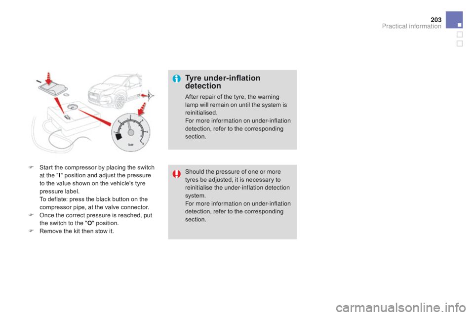
F Start the compressor b y p lacing t he s witch at t
he "I" p
osition a nd a djust t he p ressure to t
he
v
alue
s
hown
o
n
t
he
v
ehicle's
t
yre
pr
essure
l
abel.
To d
eflate:
p
ress
t
he
b
lack
b
utton
o
n
t
he
co
mpressor
p
ipe,
a
t
t
he
v
alve
c
onnector.
F
On
ce the correct pressure is reached, put
the switch to the " O"
p
osition.
F
Re
move
t
he
k
it
t
hen
s
tow
i
t.
Tyre under-inflation
detection
After repair of the tyre, the warning lamp will remain on until the system is
reinitialised.
For more information on under-inflation
detection,
r
efer
t
o
t
he
c
orresponding
sec
tion.
Should the pressure of one or more
tyres
b
e
a
djusted,
i
t
i
s
n
ecessary
t
o
rei
nitialise the under-inflation detection
system.
For more information on under-inflation
detection,
r
efer
t
o
t
he
c
orresponding
sec
tion.
Practical information
Page 206 of 444
DS3_en_Chap08_info-pratiques_ed02-2015
Changing a wheelProcedure for changing a faulty wheel for the spare wheel using the tools provided with the vehicle.
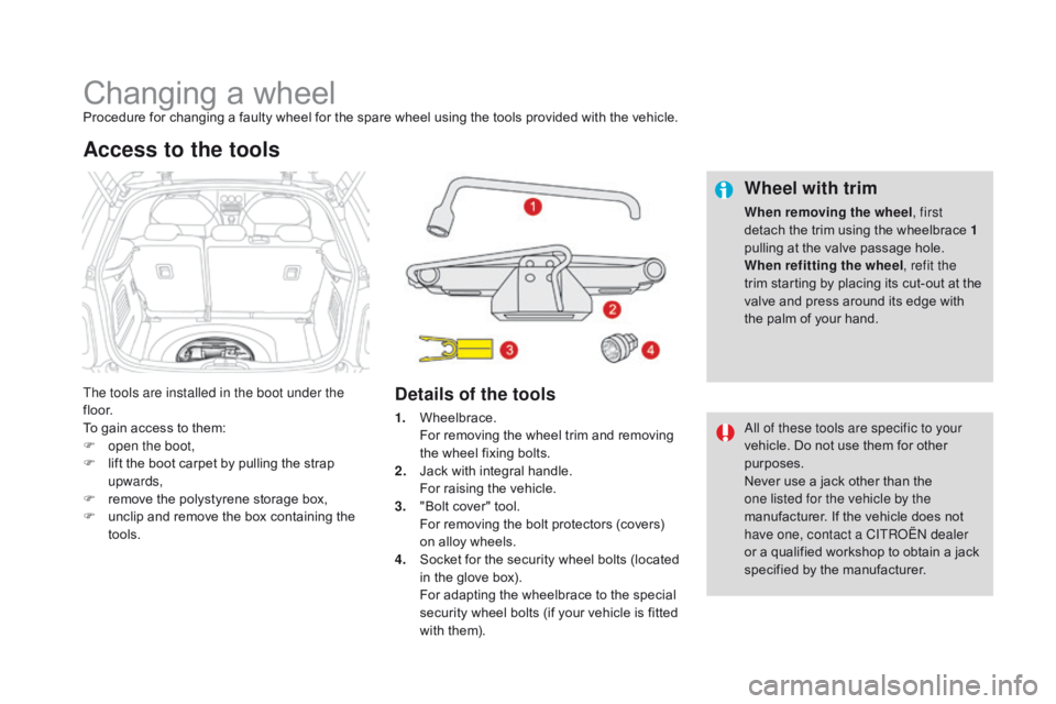
Th e tools are installed in the boot under the
f l o o r.
To
g
ain
a
ccess
t
o
t
hem:
F
op
en the boot,
F
li
ft
t
he
b
oot
c
arpet
b
y
p
ulling
t
he
s
trap
upw
ards,
F
re
move
t
he
p
olystyrene
s
torage
b
ox,
F
un
clip
a
nd
r
emove
t
he
b
ox
c
ontaining
t
he
too
ls.
Access to the tools
Details of the tools Wheel with trim
When removing the wheel
, first
detach t he t rim u sing t he w heelbrace 1
pulling
a
t
t
he
v
alve
p
assage
h
ole.
When refitting the wheel , refit the
trim
s
tarting
b
y
p
lacing
i
ts
c
ut-out
a
t
t
he
va
lve
a
nd
p
ress
a
round
i
ts
e
dge
w
ith
th
e
p
alm
o
f
y
our
h
and.
1.
Wh
eelbrace.
Fo
r
r
emoving
t
he
w
heel
t
rim
a
nd
r
emoving
th
e
w
heel
f
ixing
b
olts.
2.
Ja
ck
w
ith
i
ntegral
h
andle.
Fo
r
r
aising
t
he
v
ehicle.
3.
"B
olt
c
over"
t
ool.
Fo
r
r
emoving
t
he
b
olt
p
rotectors
(
covers)
on a
lloy
w
heels.
4.
So
cket
f
or
t
he
s
ecurity
w
heel
b
olts
(
located
in t
he
g
love
b
ox).
Fo
r
a
dapting
t
he
w
heelbrace
t
o
t
he
s
pecial
se
curity
w
heel
b
olts
(
if
y
our
v
ehicle
i
s
f
itted
wi
th
t
hem). All of these tools are specific to your
vehicle.
D
o
n
ot
u
se
t
hem
f
or
o
ther
pu
rposes.
Never
u
se
a j
ack
o
ther
t
han
t
he
on
e listed for the vehicle by the
manufacturer.
I
f
t
he
v
ehicle
d
oes
n
ot
ha
ve one, contact a CITROËN dealer
or
a q
ualified
w
orkshop
t
o
o
btain
a j
ack
sp
ecified
b
y
t
he
m
anufacturer.
Page 207 of 444
205
DS3_en_Chap08_info-pratiques_ed02-2015
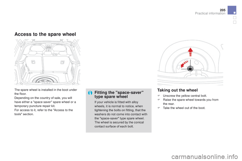
The spare wheel is installed in the boot under
the floor.
Depending
o
n
t
he
c
ountry
o
f
s
ale,
y
ou
w
ill
ha
ve either a "space saver" spare wheel or a
temporary
p
uncture
r
epair
k
it.
For access to it, refer to the "Access to the
tools"
se
ction.
Access to the spare wheel
Fitting the "space-saver"
type spare wheel
If your vehicle is fitted with alloy
wheels, it is normal to notice, when
tightening
t
he
b
olts
o
n
f
itting,
t
hat
t
he
wa
shers do not come into contact with
the
"
space-saver"
t
ype
s
pare
w
heel.
Th
e wheel is secured by the conical
contact
s
ur face
o
f
e
ach
b
olt.
Taking out the wheel
F Unscrew the ye llow c entral b olt.
F Ra ise the spare wheel towards you from
the
r
ear.
F
Ta
ke
t
he
w
heel
o
ut
o
f
t
he
b
oot.
Practical information
Page 208 of 444
DS3_en_Chap08_info-pratiques_ed02-2015
Putting the wheel back in place
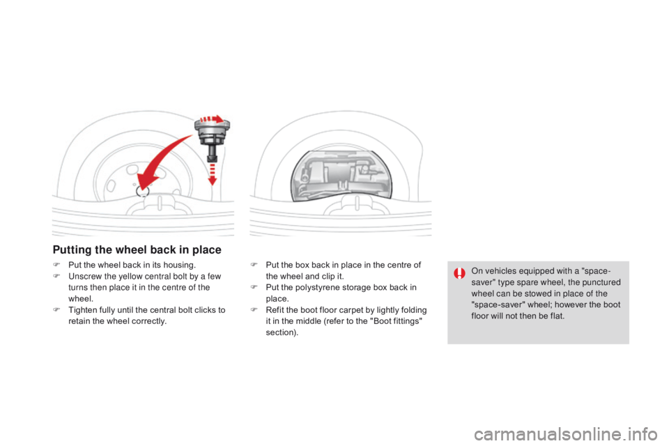
F Put the box b ack i n p lace i n t he c entre o f th
e w heel a nd c lip i t.
F
Pu
t
t
he
p
olystyrene
s
torage
b
ox
b
ack
i
n
pl
ace.
F
Re
fit
t
he
b
oot
f
loor
c
arpet
b
y
l
ightly
f
olding
it i
n
t
he
m
iddle
(
refer
t
o
t
he
"
Boot
f
ittings"
sec
tion).
F Pu
t t
he w
heel b
ack i
n i
ts h
ousing.
F Un
screw the yellow central bolt by a few
turns then place it in the centre of the
wheel.
F
Ti
ghten
f
ully
u
ntil
t
he
c
entral
b
olt
c
licks
t
o
re
tain
t
he
w
heel
c
orrectly. On vehicles equipped with a "space-
saver" type spare wheel, the punctured
wheel can be stowed in place of the
"space-saver"
w
heel;
h
owever
t
he
b
oot
fl
oor
w
ill
n
ot
t
hen
b
e
f
lat.
Page 209 of 444
207
DS3_en_Chap08_info-pratiques_ed02-2015
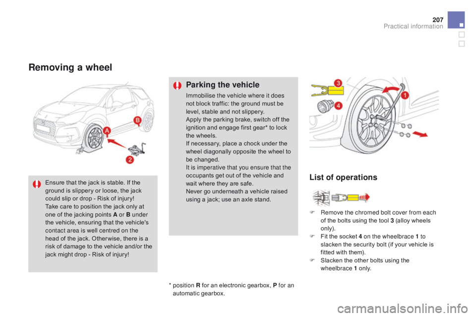
Removing a wheel
Parking the vehicle
Immobilise the vehicle where it does
not block t raffic: t he g round m ust b e le
vel,
s
table
a
nd
n
ot
s
lippery.
Apply
t
he
p
arking
b
rake,
s
witch
o
ff
t
he
ig
nition
a
nd
e
ngage
f
irst
g
ear*
t
o
l
ock
th
e
w
heels.
If
n
ecessary,
p
lace
a c
hock
u
nder
t
he
wh
eel
d
iagonally
o
pposite
t
he
w
heel
t
o
be ch
anged.
It is imperative that you ensure that the
occupants
g
et
o
ut
o
f
t
he
v
ehicle
a
nd
wa
it
w
here
t
hey
a
re
s
afe.
Never
g
o
u
nderneath
a v
ehicle
r
aised
us
ing
a j
ack;
u
se
a
n
a
xle
s
tand.F
Re
move the chromed bolt cover from each
of
t
he
b
olts
u
sing
t
he
t
ool
3 (
alloy
w
heels
on
ly).
F
Fi
t
t
he
s
ocket
4
on the wheelbrace 1 to
slacken
t
he
s
ecurity
b
olt
(
if
y
our
v
ehicle
i
s
fi
tted
w
ith
t
hem).
F
Sl
acken
t
he
o
ther
b
olts
u
sing
t
he
wh
eelbrace 1
o n
l y.
*
p
osition R
f
or
a
n
e
lectronic
g
earbox,
P
for an
automatic
g
earbox.
Ensure
t
hat
t
he
j
ack
i
s
s
table.
I
f
t
he
gr
ound
i
s
s
lippery
o
r
l
oose,
t
he
j
ack
co
uld
s
lip
o
r
d
rop
- R
isk
o
f
i
njury!
Take
c
are
t
o
p
osition
t
he
j
ack
o
nly
a
t
on
e
o
f
t
he
j
acking
p
oints
A
or B
u
nder
the
v
ehicle,
e
nsuring
t
hat
t
he
v
ehicle's
co
ntact area is well centred on the
head
o
f
t
he
j
ack.
O
ther wise,
t
here
i
s
a ri
sk
o
f
d
amage
t
o
t
he
v
ehicle
a
nd/or
t
he
ja
ck
m
ight
d
rop
- R
isk
o
f
i
njury!
List of operations
Practical information
Page 210 of 444

DS3_en_Chap08_info-pratiques_ed02-2015
F Position the f oot o f t he j ack 2 o n t he g round an
d ensure that it is directly below the
front
A
or rear B
j
acking
p
oint
p
rovided
o
n
the
underbody, whichever is closest to the
wheel
t
o
b
e
c
hanged.
On v
ehicles fitted with sill finishers, the
jacking
l
ocation
i
s
i
ndicated
b
y
a m
arking
on t
he
f
inisher.
T
he
j
ack
m
ust
b
e
p
laced
ce
ntrally
i
n
l
ine
w
ith
t
his
m
arking,
a
t
t
he
ja
cking
p
oint
l
ocated
b
ehind
t
he
f
inisher
an
d
n
ot
o
n
t
he
p
lastic
f
inisher
i
tself. F Re
move the bolts and store them in a clean
place.
F
Re
move
t
he
w
heel.
F Ex
tend t he j ack 2 until its head comes into
contact w ith t he j acking p oint A or B u sed. Th
e contact area A or B on the vehicle
must
b
e
e
ngaged
w
ith
t
he
c
entral
p
art
o
f
th
e
h
ead
o
f
t
he
j
ack.
F
Rai
se the vehicle until there is sufficient
space
b
etween
t
he
w
heel
a
nd
t
he
g
round
so t
hat
t
he
s
pare
(
not
p
unctured)
w
heel
c
an
th
en
b
e
f
itted
w
ithout
d
ifficulty.