engine CITROEN DS3 CROSSBACK 2021 Workshop Manual
[x] Cancel search | Manufacturer: CITROEN, Model Year: 2021, Model line: DS3 CROSSBACK, Model: CITROEN DS3 CROSSBACK 2021Pages: 244, PDF Size: 7.7 MB
Page 124 of 244
122
Driving06
For ''parallel'' parking, the space must at
a minimum be equal to the length of your
vehicle plus 0.60 m.
For ''bay'' parking, the width of the space must
be equal to the width of your vehicle plus 0.70
m.
If the parking sensors function has been
deactivated in the Driving/Vehicle menu
of the touch screen, it will be automatically
reactivated when the system is activated.
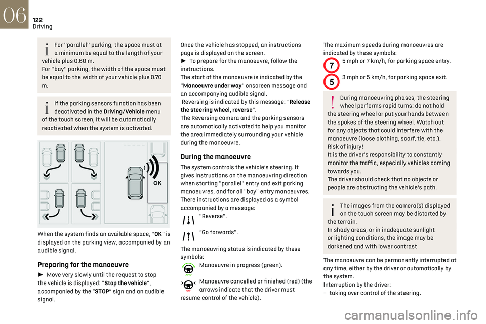
When the system finds an available space, "OK" is
displayed on the parking view, accompanied by an
audible signal.
Preparing for the manoeuvre
► Move very slowly until the request to stop
the vehicle is displayed: "Stop the vehicle“,
accompanied by the “STOP” sign and an audible
signal. Once the vehicle has stopped, an instructions
page is displayed on the screen.
►
To prepare for the manoeuvre, follow the
instructions.
The start of the manoeuvre is indicated by the
"Manoeuvre under way" onscreen message and
an accompanying audible signal.
Reversing is indicated by this message: “Release
the steering wheel, reverse”.
The Reversing camera and the parking sensors
are automatically activated to help you monitor
the area immediately surrounding your vehicle
during the manoeuvre.
During the manoeuvre
The system controls the vehicle’s steering. It
gives instructions on the manoeuvring direction
when starting "parallel" entry and exit parking
manoeuvres, and for all "bay" entry manoeuvres.
There instructions are displayed as a symbol
accompanied by a message:
"Reverse".
“Go forwards".
The manoeuvring status is indicated by these
symbols:
Manoeuvre in progress (green).
Manoeuvre cancelled or finished (red) (the
arrows indicate that the driver must
resume control of the vehicle).
The maximum speeds during manoeuvres are
indicated by these symbols:
75 mph or 7 km/h, for parking space entry.
53 mph or 5 km/h, for parking space exit.
During manoeuvring phases, the steering
wheel performs rapid turns: do not hold
the steering wheel or put your hands between
the spokes of the steering wheel. Watch out
for any objects that could interfere with the
manoeuvre (loose clothing, scarf, tie, etc.).
Risk of injury!
It is the driver's responsibility to constantly
monitor the traffic, especially vehicles coming
towards you.
The driver should check that no objects or
people are obstructing the vehicle’s path.
The images from the camera(s) displayed
on the touch screen may be distorted by
the terrain.
In shady areas, or in inadequate sunlight
or lighting conditions, the image may be
darkened and with lower contrast
The manoeuvre can be permanently interrupted at
any time, either by the driver or automatically by
the system.
Interruption by the driver:
–
t
aking over control of the steering.
– activating the direction indicator lamps on the
opposite side to that of the manoeuvre.
– unfastening the driver's seat belt.
– switching off the ignition.
Interruption by the system:
– vehicle exceeding the speed limit of 5 mph
(7 km/h) during parking space entry manoeuvres,
or 3 mph (5 km/h) during parking space exit
manoeuvres.
– activation of anti-slip regulation on a slippery
road.
– opening of a door or the boot.
– engine stall.
– system malfunction.
– after 10 manoeuvres to enter or exit a parallel
parking space and after 7 manoeuvres to enter a
parking bay.
Interrupting the manoeuvre automatically
deactivates the function.
The manoeuvre symbol is displayed in red,
accompanied by the "Manoeuvre cancelled"
message on the touch screen.
A message prompts the driver to take back
control of the vehicle.
The function is deactivated after a few
seconds; this warning lamp goes off and
the function returns to the initial display.
End of the parking space entry or exit
manoeuvre
The vehicle stops as soon as the manoeuvre is
completed.
Page 125 of 244
123
Driving06
– activating the direction indicator lamps on the
opposite side to that of the manoeuvre.
–
un
fastening the driver's seat belt.
–
s
witching off the ignition.
Interruption by the system:
–
v
ehicle exceeding the speed limit of 5 mph
(7 km/h) during parking space entry manoeuvres,
or 3 mph (5 km/h) during parking space exit
manoeuvres.
–
activ
ation of anti-slip regulation on a slippery
road.
–
opening o
f a door or the boot.
–
engine st
all.
–
s
ystem malfunction.
–
a
fter 10 manoeuvres to enter or exit a parallel
parking space and after 7 manoeuvres to enter a
parking bay.
Interrupting the manoeuvre automatically
deactivates the function.
The manoeuvre symbol is displayed in red,
accompanied by the "Manoeuvre cancelled"
message on the touch screen.
A message prompts the driver to take back
control of the vehicle.
The function is deactivated after a few
seconds; this warning lamp goes off and
the function returns to the initial display.
End of the parking space entry or exit
manoeuvre
The vehicle stops as soon as the manoeuvre is
completed. The manoeuvring symbol is displayed in red
accompanied by the message “Manoeuvre
completed” on the touch screen.
Deactivation of the function is confirmed
by this indicator lamp going off,
accompanied by an audible signal.
If entering a parking space, the driver may be
required to complete the manoeuvre.
Operating limits
– The system may suggest an inappropriate
parking space (parking prohibited, work in
progress with damaged road surface, location
alongside a ditch, etc.).
–
The s
ystem may indicate that a space has
been found but will not offer it because of a fixed
obstacle on the opposite side of the manoeuvre,
which would not allow the vehicle to follow a
trajectory required for parking.
–
The s
ystem may indicate that a space has been
found but the manoeuvre will not be triggered,
because the width of the lane is insufficient.
–
The s
ystem is not designed for performing the
parking manoeuvre on a sharp bend.
–
The s
ystem does not detect spaces that
are much larger than the vehicle itself or that
are delimited by obstacles that are too low
(pavements, studs, etc.) or too thin (trees, posts,
wire fences, etc.).
–
If the boo
t is heavily loaded, the tilt of the
vehicle towards the rear may interfere with the
distance measurements.
Do not use the function under the
following exterior conditions:
–
Alongside a so
ft shoulder (e.g. ditch) or quay
or on the edge of a drop.
–
When the road surfac
e is slippery (e.g. ice).
If any of the following malfunctions
occurs, do not use the system:
–
If a tyre is under-in
flated.
–
If one o
f the bumpers is damaged.
–
If one o
f the cameras is faulty.
If the vehicle has undergone any of the
following modifications, do not use the
function:
–
When c
arrying an object extending beyond
the dimensions of the vehicle (ladder on the
roof bars, bicycle carrier on the tailgate, etc.).
–
With a non-appro
ved towball in place.
–
With sno
w chains fitted.
–
When driving on a small-diamet
er or "space-
saver" type spare wheel.
–
When the wheels fitt
ed are a different size
from the original ones.
–
A
fter modifying one or both bumpers (added
protection).
–
If the sensors ha
ve been repainted other
than by the dealer network.
–
With sensors no
t approved for the vehicle.
Page 128 of 244

126
Driving06
an obstacle is detected, or by driver action. If the
driver notices a hazard, they may also interrupt
the manoeuvre permanently.
To suspend the manoeuvre, the driver can:
–
R
elease the function control button.
–
Depre
ss the brake pedal.
–
R
esume control of the steering.
–
C
hange the gearbox status (except changing
to P).
The vehicle is immediately immobilised if the
manoeuvre is suspended.
This is confirmed by the display of this
symbol, accompanied by the message
"Manoeuvre suspended".
Resuming the manoeuvre after resolving the
conditions for suspending it:
► Release all controls (brake pedal, function
control button, steering wheel, etc.).
► Press the function control button again.
Permanent interruption after suspending the
manoeuvre:
► Depress the brake pedal and engage a gear.
Abandoning the manoeuvre
The manoeuvre is abandoned in the following
situations:
–
No action b
y the driver within 30 seconds of the
manoeuvre being suspended.
–
In
tentional application of the parking brake.
–
Gearbo
x mode P engaged by the driver.
–
D
river's seat belt unfastened.
–
O
pening of a door or the boot. –
Activ
ation of the direction indicator lamps on
the opposite side to that of the manoeuvre.
–
In c
ertain cases, when a wheel of the vehicle
hits a pavement or a low obstacle.
–
Triggering o
f anti-slip regulation on a slippery
road.
–
Engine st
alling.
–
Sudden appearanc
e in the field of the
manoeuvre of an obstacle not detected by the
system before the manoeuvre was started, with
the obstacle remaining for more than 30 seconds.
–
A
fter 10 manoeuvres to enter or exit a "parallel"
parking space and after 7 manoeuvres to enter a
"bay" parking space,
–
Sy
stem malfunction during the manoeuvre.
Abandoning the manoeuvre immediately
triggers the vehicle’s brakes and automatically
deactivates the function.
This symbol is displayed, accompanied by
the message "Manoeuvre abandoned" on
the touch screen.
A message prompts the driver to take back
control of the vehicle.
The function is deactivated after a few
seconds; this indicator lamp goes off on
the instrument panel and the initial display is
resumed.
The system automatically engages gearbox mode
P after 4 seconds.
End of manoeuvre
The vehicle stops as soon as the manoeuvre is
completed.
This symbol is displayed, accompanied by
the message "Manoeuvre completed" on
the touch screen.
When the function is deactivated, this
indicator lamp on the instrument panel
goes off and the original display is restored.
–
If en
tering a parking space, the driver may be
required to complete the manoeuvre. The gearbox
changes to P 4 seconds after completion of the
manoeuvre.
–
When e
xiting a parking space, the gearbox
changes to N when the manoeuvre is complete. A
message and symbols prompt the driver to take
back control of the vehicle.
The gearbox automatically changes to mode
P if no action is taken by the driver within 30
secondss.
Operating limits
– The system may suggest an inappropriate
parking space (parking prohibited, work in
progress with damaged road surface, location
alongside a ditch, etc.).
–
The s
ystem may indicate that a space has
been found but will not offer it because of a fixed
obstacle on the opposite side of the manoeuvre,
which does not allow the vehicle to follow the
trajectory required for parking.
–
The s
ystem may indicate that a space has been
found but the manoeuvre will not be triggered
because the width of the lane is insufficient.
–
The s
ystem is not designed to perform parking
manoeuvres on a steep slope or on a sharp curve.
– The system does not detect spaces that
are much larger than the vehicle itself or that
are delimited by obstacles that are too low
(pavements, studs, etc.) or too thin (trees, posts,
wire fences, etc.).
– The system may be impaired by incorrect
inflation of the vehicle’s tyres.
– The tilting of the vehicle if the boot is heavily
loaded can affect the distance measurements.
Do not use the function under the
following exterior conditions:
– Alongside a soft shoulder (ditch) or quay or
on the edge of a drop.
– When the road surface is slippery (ice).
Do not use the function in the presence of
one of the following malfunctions:
– If a tyre is under-inflated.
– If one of the bumpers is damaged.
– If one of the cameras is faulty.
– If the brake lamps are not working.
Do not use the function if the vehicle has
been subject to one of the following
modifications:
– When carrying an object extending beyond
the dimensions of the vehicle (ladder on the
roof bars, bicycle carrier on the tailgate, etc.).
– With a non-approved towball in place.
– With snow chains fitted.
– When driving on a small-diameter or "space-
saver" type spare wheel.
Page 130 of 244

DS
Compatibility of fuels
Petrol fuels conforming to the EN228 standard
containing up to 5% and 10% ethanol respectively.
Diesel fuels conforming to the EN590, EN16734
and EN16709 standards and containing up to
7%, 10%, 20% and 30% fatty acid methyl ester
respectively. The use of B20 or B30 fuels, even
occasionally, imposes special maintenance
conditions referred to as "Arduous conditions".
Paraffinic Diesel fuel conforming to the EN15940
standard.The use of any other type of (bio) fuel
(vegetable or animal oils, pure or diluted,
domestic fuel, etc.) is strictly prohibited (risk
of damage to the engine and fuel system).
The only fuel additives authorised for use
are those that meet the B715001 (petrol)
or B715000 (Diesel) standards.
Diesel at low temperature
At temperatures below 0 °C (+32 °F), the
formation of paraffins in summer-type Diesel
fuels could prevent the engine from operating
For more than 50 years, TOTAL
and DS have shared common
values: excellence, creativity and
technological innovation.
It is in this same spirit that TOTAL
has developed a range of TOTAL
QUARTZ lubricants adapted to DS
engines, making them ever more
fuel ef cient and environmentally
friendly.
Choose TOTAL QUARTZ
lubricants for servicing your
vehicle; they are your assurance
of optimum engine life and
performance.
BESPOKE
LUBRICANTS FOR
LUXURY CARS
Page 131 of 244
DS
129
Practical information07
Compatibility of fuels
Petrol fuels conforming to the EN228 standard
containing up to 5% and 10% ethanol respectively.
Diesel fuels conforming to the EN590, EN16734
and EN16709 standards and containing up to
7%, 10%, 20% and 30% fatty acid methyl ester
respectively. The use of B20 or B30 fuels, even
occasionally, imposes special maintenance
conditions referred to as "Arduous conditions".
Paraffinic Diesel fuel conforming to the EN15940
standard.
The use of any other type of (bio) fuel
(vegetable or animal oils, pure or diluted,
domestic fuel, etc.) is strictly prohibited (risk
of damage to the engine and fuel system).
The only fuel additives authorised for use
are those that meet the B715001 (petrol)
or B715000 (Diesel) standards.
Diesel at low temperature
At temperatures below 0 °C (+32 °F), the
formation of paraffins in summer-type Diesel
fuels could prevent the engine from operating correctly. In these temperature conditions, use
winter-type Diesel fuel and keep the fuel tank
more than 50 % full.
At temperatures below -15 °C (+5 °F) to avoid
problems starting, it is best to park the vehicle
under shelter (heated garage).
Travelling abroad
Certain fuels could damage your vehicle’s engine.
In certain countries, the use of a particular fuel
may be required (specific octane rating, specific
trade name, etc.) to ensure correct operation of
the engine.
For all additional information, consult a dealer.
Refuelling
Fuel tank capacity: approximately 44 litres
(petrol) or 41 litres (Diesel).
Reserve level: approximately 6 litres.
Low fuel level
When the low fuel level is reached, this
warning lamp comes on on the instrument
panel, accompanied by an onscreen message and
an audible signal. When it first comes on, about 6
litres of fuel remain in the tank.
Until sufficient fuel is added, this warning lamp
appears every time the ignition is switched on,
accompanied by an onscreen message and an
audible signal. When driving, this message and
audible signal are repeated with increasing
frequency as the fuel level drops towards 0.
You must refuel as soon as possible to avoid
running out of fuel.
For more information on Running out of fuel
(Diesel), refer to the corresponding section.
Stop & Start
Never refuel with the engine in STOP
mode; you must switch off the ignition.
Refuelling
Additions of fuel must be of at least 5 litres, in
order to be registered by the fuel gauge.
Opening the filler cap may create a noise caused
by an inrush of air. This vacuum is entirely normal,
resulting from the sealing of the fuel system.
To refuel in complete safety:
► You must switch off the engine.
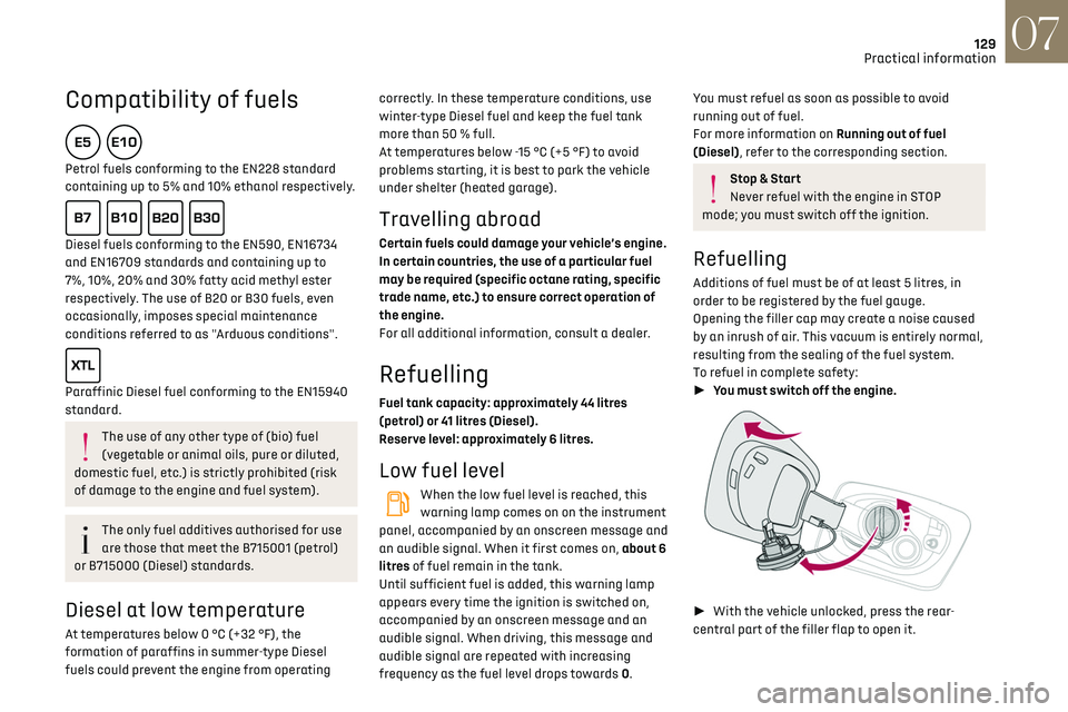
►With the vehicle unlocked, press the rear-
central part of the filler flap to open it.
Page 132 of 244

130
Practical information07
► Take care to select the pump that delivers the
correct fuel type for the vehicle's engine (see a
reminder label on the inside of the filler flap).
► Turn the filler cap to the left.
► Remove the filler cap and hang it on its carrier
(on the filler flap).
► Introduce the filler nozzle and push it in as
far as possible before starting to refuel (risk of
blowback).
► Fill the tank.
Do not continue past the third cut-off of the
nozzle, as this may cause malfunctions.
► Refit the filler cap.
► Turn it to the right.
► Push the filler flap to close it.
If you have put in the wrong fuel for the
vehicle, you must have the fuel tank
drained and filled with the correct fuel before
starting the engine.
The vehicle is fitted with a catalytic converter, a
device which helps to reduce the level of harmful
emissions in the exhaust gases.
For petrol engines, you must use unleaded fuel.
The filler neck is narrower, admitting unleaded
petrol nozzles only.
Misfuel prevention (Diesel)
(Depending on country of sale.)
This mechanical device prevents filling the tank of
a Diesel vehicle with petrol.
Located in the filler neck, the misfuel prevention
device is visible when the filler cap is removed.
Operation
When a petrol filler nozzle is inserted into the
fuel filler neck of a Diesel vehicle, it comes into
contact with the flap. The system remains closed
and prevents filling.
Do not persist but introduce a Diesel type filler
nozzle.
It remains possible to use a fuel jerrycan
to fill the tank.
Travelling abroad
As Diesel fuel pump nozzles may be
different in other countries, the presence
of the misfuel prevention device may make
refuelling impossible.
Before travelling abroad, it is advisable to
check with a dealer if the vehicle is suitable
for the distribution equipment of the countries
visited.
Charging system (Electric)
400 V electrical system
The electrical system, which operates at a voltage
of approximately 400 V, is identified by orange
cables, and its components are marked with this
symbol:
An electric vehicle’s power train can
become hot during use and after
switching off the ignition.
Observe the warning messages shown on
labels, particularly inside the flap.
All work on or modifications to the vehicle’s
electrical system (including the traction
battery, connectors, orange cables and
other components visible from the interior or
exterior) is strictly prohibited - risk of severe
burns or potentially fatal electric shock (short-
circuit / electrocution)!
In the event of a problem, always contact a
dealer or a qualified workshop.
This label is intended solely for use by
firefighters responding to an incident
involving the vehicle and for maintenance
technicians.
Never allow water or dust to enter the
connector or charging nozzle - risk of
electrocution or fire!
Never connect / disconnect the charging
nozzle or cable with wet hands - risk of
electrocution!
In the event of an accident or impact
The electrical system or the traction
battery may be seriously damaged in the event
of an accident or impact involving the vehicle
underbody.
Stop as soon as it is safe to do so and switch
off the ignition.
Contact a dealer or a qualified workshop
without delay.
In the event of exposure to a fire
Immediately exit and evacuate all
passengers from the vehicle. Never attempt to
fight the fire yourself - risk of electrocution!
Page 136 of 244
134
Practical information07
4.Always use an electrical socket protected
by a circuit-breaker appropriate for the
electrical circuit’s current rating.
5. The weight of the control unit must not be
borne by the electrical socket, plug and
cables.
6. Never use this charging cable if it is defective
or in any way damaged.
7. Never attempt to repair or open this charging
cable. It contains no repairable parts -
replace the charging cable if it is damaged.
8. Never immerse this charging cable in water.
9. Never use this charging cable with an
extension cable, a multi-plug socket,
a conversion adaptor or on a damaged
electrical socket.
10. Do not unplug the plug from the wall as a
means of stopping charging.
11. Do not force the connector if it is locked into
the vehicle.
12. Immediately stop charging, by locking and
then unlocking the vehicle using the remote
control key, if the charging cable or wall
socket feel burning hot to the touch.
13. This charging cable includes components
liable to cause electrical arcing or sparks. Do
not expose to flammable vapours.
14. Only use this charging cable with DS
AUTOMOBILES vehicles.
15. Never plug the cable into the wall socket (or
unplug it) with wet hands.Charging the traction
battery (Electric)
To recharge, connect the vehicle to a domestic
electrical system (for domestic or accelerated
charging) or a fast charging station (for fast
charging).
For a full charge, follow the desired charging
procedure without pausing it, until it ends
automatically. Charging may be performed either
immediately or deferred.
You can stop charging at any time by unlocking
the vehicle and removing the nozzle.
For more information on the charging displays on
the Instrument panel and the Touch screen, refer
to the corresponding section.
Depending on version, the deferred charge
function is configured via either the touch
screen or the MyDS application.
For more information on the deferred charge
function, refer to the corresponding section.
A LED, located below the interior rear view
and visible from outside the vehicle,
flashes in blue for a few minutes to confirm
the start of the charging.
It is also possible to monitor the charging
process using the MyDS application.
For more information on Remotely operable
features, refer to the corresponding section.
As a safety measure, the engine will not
start if the charging cable is plugged into
the connector on the vehicle. A warning is
displayed on the instrument panel.
Cooling the traction battery
The cooling fan comes on during charging
to cool the on-board charger and the traction
battery.
Vehicle unused for an extended period
Fully recharge the traction battery every
three months. Follow the domestic charging
procedure.
Before carrying out the charging operation,
check that the accessory battery is not
disconnected or discharged. If it is, refer to
the corresponding section for information on
reconnecting or recharging it.
Precautions
Electric vehicles were developed in accordance
with the guidelines on maximum electromagnetic
fields issued by the International Commission on
Non-Ionizing Radiation Protection (ICNIRP - 1998
Guidelines).
Wearers of pacemakers or equivalent
devices should consult a doctor to enquire
about any applicable precautionary measures, or
contact the manufacturer of their implanted
electronic medical device to check that it is
guaranteed to operate in an environment
compliant with the ICNIRP guidelines.
If in doubt
Domestic or accelerated charging: do
not remain inside or near the vehicle, or near
the charging cable or charging unit, even for a
short time.
Fast charging: do not use the system yourself
and avoid approaching public fast charging
points. Leave the area and ask a third party to
recharge the vehicle.
For domestic or accelerated charging
Before charging
Depending on the context:
► Have a professional check that the
electrical system to be used complies with
applicable standards and is compatible with
the vehicle.
► Have a professional electrician install
a dedicated domestic power socket or
accelerated charging unit (Wallbox)
compatible with the vehicle.
Use the charging cable supplied with the
vehicle.
(During charging)
Never work under the bonnet:
– Some areas remain very hot, even an hour
after charging ends - risk of burns!
– The fan may start at any time - risk of cuts or
strangulation!
Page 138 of 244
136
Practical information07
The red indicator lamp in the flap comes on to
indicate that the nozzle is locked.
If charging has finished but the cable is
still connected, opening the driver's door
restarts charging for around 20 seconds.
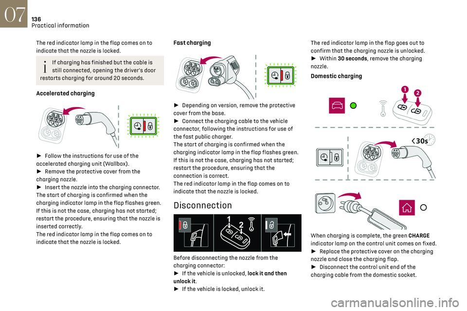
Accelerated charging
► Follow the instructions for use of the
accelerated charging unit (Wallbox).
► Remove the protective cover from the
charging nozzle.
► Insert the nozzle into the charging connector.
The start of charging is confirmed when the
charging indicator lamp in the flap flashes green.
If this is not the case, charging has not started;
restart the procedure, ensuring that the nozzle is
inserted correctly.
The red indicator lamp in the flap comes on to
indicate that the nozzle is locked.
Fast charging
► Depending on version, remove the protective
cover from the base.
► Connect the charging cable to the vehicle
connector, following the instructions for use of
the fast public charger.
The start of charging is confirmed when the
charging indicator lamp in the flap flashes green.
If this is not the case, charging has not started;
restart the procedure, ensuring that the
connection is correct.
The red indicator lamp in the flap comes on to
indicate that the nozzle is locked.
Disconnection
Before disconnecting the nozzle from the
charging connector:
► If the vehicle is unlocked, lock it and then
unlock it.
► If the vehicle is locked, unlock it. The red indicator lamp in the flap goes out to
confirm that the charging nozzle is unlocked.
►
Within 30 seconds, remove the charging
nozzle.
Domestic charging
When charging is complete, the green CHARGE
indicator lamp on the control unit comes on fixed.
► Replace the protective cover on the charging
nozzle and close the charging flap.
► Disconnect the control unit end of the
charging cable from the domestic socket.
Accelerated charging
The end of charging is indicated by the charging
control unit and by the fixed lighting of the green
indicator lamp in the flap.
► Hang up the nozzle on the charging unit and
close the charging flap.
Fast charging
The end of charging is indicated by the charger
and by the fixed lighting of the green indicator
lamp in the flap.
► Hang up the nozzle on the charging station.
► Depending on version, replace the protective
cover on the base and close the charging flap.
Towing device
Load distribution
► Distribute the load in the trailer so that
the heaviest items are as close as possible to
the axle, and the nose weight approaches the
maximum permitted without exceeding it.
Air density decreases with altitude, thus reducing
engine performance. The maximum load which
can be towed must be reduced by 10% per
1,000 metres of altitude.
Use towing devices and their genuine
wiring harnesses approved by the
Manufacturer. It is recommended that the
Page 139 of 244
137
Practical information07
Accelerated charging
The end of charging is indicated by the charging
control unit and by the fixed lighting of the green
indicator lamp in the flap.
► Hang up the nozzle on the charging unit and
close the charging flap.
Fast charging
The end of charging is indicated by the charger
and by the fixed lighting of the green indicator
lamp in the flap.
► Hang up the nozzle on the charging station.
► Depending on version, replace the protective
cover on the base and close the charging flap.
Towing device
Load distribution
► Distribute the load in the trailer so that
the heaviest items are as close as possible to
the axle, and the nose weight approaches the
maximum permitted without exceeding it.
Air density decreases with altitude, thus reducing
engine performance. The maximum load which
can be towed must be reduced by 10% per
1,000 metres of altitude.
Use towing devices and their genuine
wiring harnesses approved by the
Manufacturer. It is recommended that the
fitting be performed by a dealer or a qualified
workshop.
If not fitted by a dealer, it must still be fitted
in accordance with the Manufacturer's
instructions.
Certain driving or manoeuvring aid functions
are automatically deactivated if an approved
towing system is used.
Observe the maximum authorised towable
weight, indicated on the vehicle's
registration certificate, the manufacturer's
label as well as in the Technical data section of
this guide.
Complying with the maximum authorised
nose weight (towball) also includes the use of
accessories (bicycle carriers, tow boxes, etc.).
Observe the legislation in force in the
country where you are driving.
Electric motor
Electric vehicles must never be equipped
with towing devices.
It is therefore not possible to tow a trailer or
caravan.
Roof bars
As a safety measure and to avoid
damaging the roof, it is essential to use
the transverse bars approved for the vehicle.
Observe the instructions on fitting and use
contained in the guide supplied with the roof
bars.
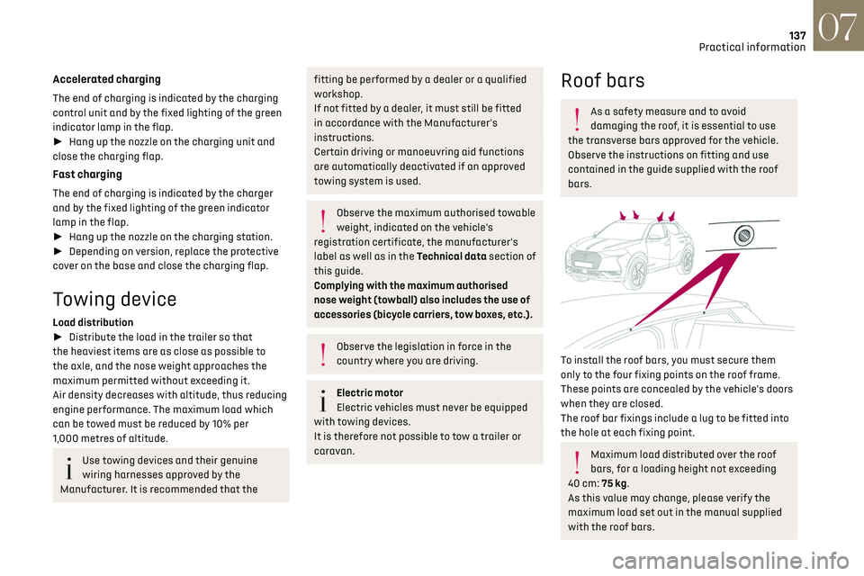
To install the roof bars, you must secure them
only to the four fixing points on the roof frame.
These points are concealed by the vehicle's doors
when they are closed.
The roof bar fixings include a lug to be fitted into
the hole at each fixing point.
Maximum load distributed over the roof
bars, for a loading height not exceeding
40 cm: 75 kg.
As this value may change, please verify the
maximum load set out in the manual supplied
with the roof bars.
Page 140 of 244

138
Practical information07
If the height exceeds 40 cm, adapt the speed
of the vehicle to the profile of the road to avoid
damaging the roof bars and the fixings on the
vehicle.
Be sure to refer to national legislation in order
to comply with the regulations for transporting
objects which are longer than the vehicle.
Recommendations
Distribute the load uniformly, taking care
to avoid overloading one of the sides.
Arrange the heaviest part of the load as close
as possible to the roof.
Secure the load firmly.
Drive gently: the vehicle will be more
susceptible to the effects of side winds and its
stability may be affected.
Regularly check the security and tight
fastening of the roof bars, at least before each
trip.
Remove the roof bars once they are no longer
needed.
Snow chains
In wintry conditions, snow chains improve
traction as well as the behaviour of the vehicle
when braking.
The snow chains must be fitted only to
the front wheels. They must never be
fitted to "space-saver" type spare wheels.
Take account of the legislation specific to
each country on the use of snow chains
and the maximum authorised speed.
Use only chains designed to be fitted to the type
of wheel fitted to the vehicle:
Original tyre size Chain type 215/65 R16 Cannot be fitted with chains
215/60 R17 Polaire XP9 with manual locking
215/55R18 Cannot be fitted with chains
For more information on snow chains, contact a
dealer or a qualified workshop.
Installation tips
► To fit the chains during a journey, stop the
vehicle on a flat surface on the side of the road.
► Apply the parking brake and position any
wheel chocks under the wheels to prevent
movement of the vehicle.
► Fit the chains following the instructions
provided by the manufacturer.
► Move off gently and drive for a few moments,
without exceeding 31 mph (50 km/h).
► Stop the vehicle and check that the snow
chains are correctly tightened.
It is strongly recommended that before
you leave, you practise fitting the snow
chains on a level and dry surface.
Avoid driving with snow chains on roads
that have been cleared of snow to avoid
damaging the vehicle's tyres and the road
surface. If the vehicle is fitted with alloy
wheels, check that no part of the chain or its
fixings is in contact with the wheel rim.
Energy economy mode
This system manages the duration of use of
certain functions, in order to conserve a sufficient
level of charge in the battery with the ignition off.
After switching off the engine, you can still
use functions such as the audio and telematic
system, the wipers and the dipped beam
headlamps or courtesy lamps, for a combined
duration of approximately 40 minutes.
Selecting the mode
A confirmation message is displayed when
energy economy mode is entered, and the active
functions are placed on standby.
If a telephone call is in progress at the
time, it will be maintained for around 10
minutes via the audio system’s hands-free
system.
Exiting the mode
These functions are automatically reactivated the
next time the vehicle is used.
To restore the use of these functions immediately,
start the engine and let it run:
– For less than 10 minutes, to use the equipment
for approximately 5 minutes.
– For more than 10 minutes, to use the equipment
for approximately 30 minutes.
Let the engine run for the specified duration to
ensure that the battery charge is sufficient.
To recharge the battery, avoid repeatedly or
continuously restarting the engine.
A flat battery prevents the engine from
starting.
For more information on the 12 V battery, refer
to the corresponding section.
Load reduction mode
This system manages the use of certain functions
according to the level of charge remaining in the
battery.
When the vehicle is being driven, the load
reduction function temporarily deactivates
certain functions, such as the air conditioning
and the heated rear screen.
The deactivated functions are reactivated
automatically as soon as conditions permit.