clock Citroen GRAND C4 PICASSO RHD 2016 2.G Owner's Manual
[x] Cancel search | Manufacturer: CITROEN, Model Year: 2016, Model line: GRAND C4 PICASSO RHD, Model: Citroen GRAND C4 PICASSO RHD 2016 2.GPages: 523, PDF Size: 13.63 MB
Page 220 of 523
218
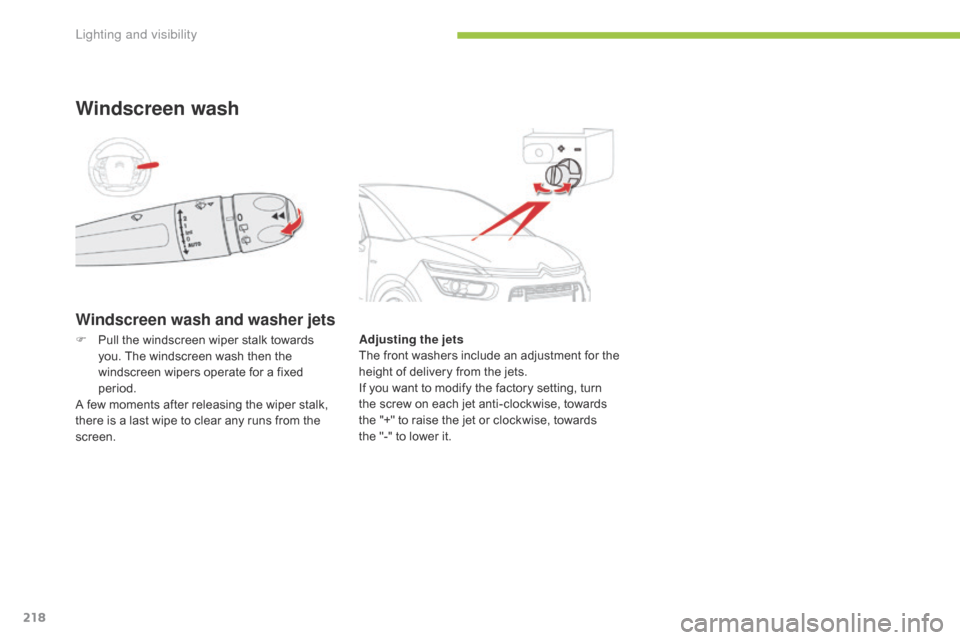
Windscreen wash and washer jets
Windscreen wash
Adjusting the jets
The f ront w ashers i nclude a n a djustment f or t he
h
eight of delivery from the jets.
If
you want to modify the factory setting, turn
t
he screw on each jet anti-clockwise, towards
t
he "+" to raise the jet or clockwise, towards
t
he "-" to lower it.
F
P
ull
the
windscreen
wiper
stalk
towards
y
ou.
The
windscreen
wash
then
the
w
indscreen
wipers
operate
for
a
fixed
p
eriod.
A
few
moments
after
releasing
the
wiper
stalk,
t
here
is
a
last
wipe
to
clear
any
runs
from
the
sc
reen.
Lighting and visibility
Page 281 of 523
279
Recommendations on storage
AdBlue® freezes at about -11°C and d
eteriorates above 25°C. It is recommended
t
hat
bottles be stored in a cool area and
p
rotected from direct sunlight.
Under
these conditions, the fluid can be kept
f
or
at
least a year.
If
the
additive has frozen, it can be used once it
h
as
completely thawed out.
Procedure
Before topping-up, ensure that the vehicle is parked on a flat and level sur face.
In
wintry conditions, ensure that the
t
emperature of the vehicle is above -11°C.
O
ther wise, by freezing, the AdBlue
® cannot
be
poured
into
its
tank.
Park
your
vehicle in a
w
armer
area
for
a
few
hours
to
allow the top-up
t
o
be
carried
out.
F
P
ress
the
START/STOP
button
to switch
o
ff
the
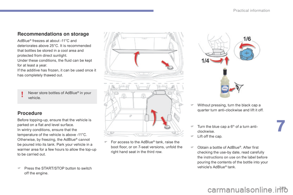
engine. F
F or access to the AdBlue® tank, raise the b
oot
floor,
or
on
7-seat
versions, unfold the
r
ight
hand
seat
in
the
third
row.
Never
store
bottles
of
AdBlue
® in your
vehicle.
F
W
ithout pressing, turn the black cap a
q
uarter turn anti-clockwise and lift it off.
F
T
urn the blue cap a 6
th of a turn anti-
c
lockwise.
F
L
ift
off
the
cap.
F
O
btain
a
bottle
of
AdBlue
®. After first c
hecking
the
use-by
date,
read carefully
t
he instructions on use on the label before
pouring
the
contents
of
the bottle into your
v
ehicle's
Ad
Blue
® tank.
7
Practical information
Page 282 of 523
280
Important: if your vehicle's AdBlue®
tank
is
completely
empty
-
which
is
c
onfirmed
by
the
alert
messages
and
t
he
impossibility
of
starting
the
engine,
y
ou
must
add
at
least
3.8
litres
of
fluid. Important: w
hen topping-up after
running out of AdBlue®, signalled b
y
the
message
"Top-up
AdBlue :
S
tarting
prevented",
you
must wait
f
or
approximately
5
minutes before
s
witching
on
the
ignition,
without
opening the driver's door, unlocking
the vehicle, placing the key of the
"Keyless Entr y and Star ting" system
inside the vehicle or inser ting the
electronic key in the reader.
Switch
on
the
ignition,
wait for
1
0 seconds,
then
start
the engine.
If
any
fluid
is
spilt
or
splashed,
wash
i
mmediately
w
ith
c
old
w
ater
o
r
w
ipe
w
ith
a
damp
cloth.
If
the
fluid
has
crystallised,
clean
it
off
u
sing
a
sponge
and
hot
water.
F
A
fter
emptying
the
bottle,
wipe
away
any
s
pillage
around
the
tank
filler
using
a
damp
c
loth. F
R
efit
the
blue
cap
to
the
tank
and
turn
it
a
6th of a turn clockwise, to its stop.
F
R
efit the black cap and turn it a quarter of
a
turn clockwise without pressing. Ensure
t
hat the indicator on the cap lines up with
t
he indicator on the support.
F
D
epending on equipment, return the spare
w
heel and/or the storage box to the bottom
o
f
the boot.
F
R
efit the boot carpet and close the tailgate.
Do
not dispose of AdBlue
® bottles in
the
household
waste.
Place them in a
c
ontainer
provided
for
this
purpose or
t
ake
them
to
your
dealer.
Practical information
Page 294 of 523
292
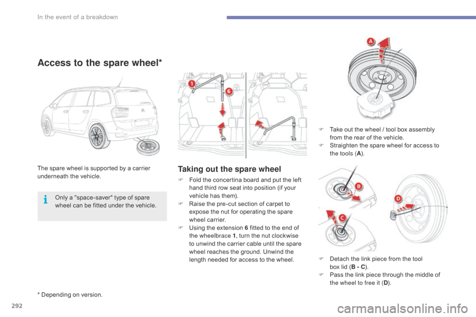
Taking out the spare wheelThe spare wheel is supported by a carrier underneath t he v ehicle.
Access to the spare wheel*
F Take out the wheel / tool box assembly f
rom the rear of the vehicle.
F
S
traighten the spare wheel for access to
t
he tools ( A).
F
F
old
the
concertina
board
and
put
the
left
h
and
third
row
seat
into
position
(if
your
v
ehicle
has
them).
F
R
aise
the
pre-cut
section
of
carpet
to
e
xpose
the
nut
for
operating
the
spare
w
heel
carrier.
F
U
sing
the
extension
6
fitted
to
the
end
of
t
he wheelbrace 1 ,
turn
the
nut
clockwise
t
o
unwind
the
carrier
cable
until
the
spare
w
heel
reaches
the
ground.
Unwind
the
l
ength
needed
for
access
to
the
wheel.
Only
a
"space-saver"
type
of
spare
w
heel
can
be
fitted
under
the
vehicle.
*
Depending
on
version. F
D
etach the link piece from the tool
b
ox lid ( B - C).
F
P
ass the link piece through the middle of
t
he wheel to free it ( D).
In the event of a breakdown
Page 295 of 523
293
A punctured wheel from the vehicle cannot be fitted under the vehicle. It
m
ust
b
e
c
arried
i
n
t
he
b
oot.
U
se
a
c
over
t
o protect the boot.
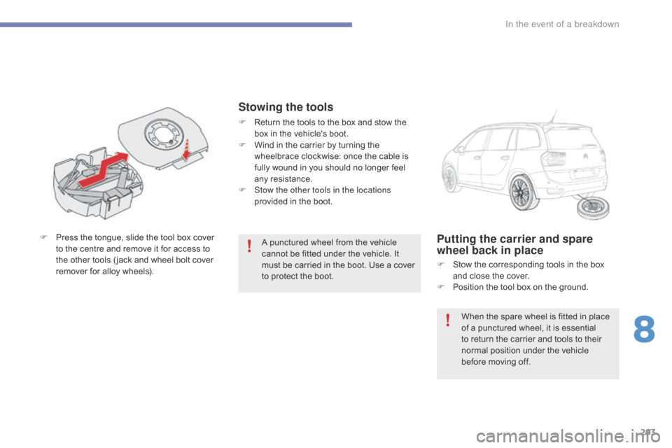
F
P
ress
the
tongue,
slide
the
tool
box
cover
t
o
the
centre
and
remove
it
for
access
to
t
he
other
tools
( jack
and
wheel
bolt
cover
r
emover
for
alloy
wheels).Putting the carrier and spare
wheel back in place
F Stow the corresponding tools in the box a
nd close the cover.
F
P
osition the tool box on the ground.
Stowing the tools
F Return the tools to the box and stow the b
ox in the vehicle's boot.
F
W
ind in the carrier by turning the
w
heelbrace clockwise: once the cable is
f
ully wound in you should no longer feel
an
y
r
esistance.
F
S
tow the other tools in the locations
provided
in the boot.
When
the spare wheel is fitted in place
o
f a punctured wheel, it is essential
t
o return the carrier and tools to their
n
ormal position under the vehicle
b
efore moving off.
8
In the event of a breakdown
Page 296 of 523
294
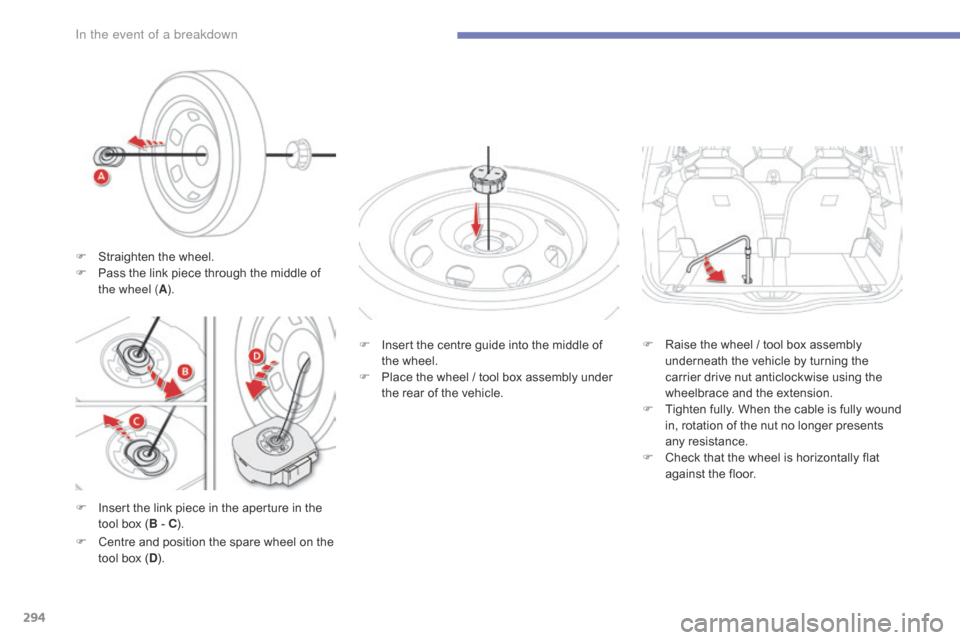
F Insert the link piece in the aperture in the t
ool box (B
- C). F
I
nsert the centre guide into the middle of
t
he wheel.
F
P
lace the wheel / tool box assembly under
t
he rear of the vehicle.
F
C
entre and position the spare wheel on the
t
ool box (D ). F
R
aise the wheel / tool box assembly
u
nderneath the vehicle by turning the
c
arrier drive nut anticlockwise using the
w
heelbrace and the extension.
F
T
ighten fully. When the cable is fully wound
i
n, rotation of the nut no longer presents
an
y
r
esistance.
F
C
heck that the wheel is horizontally flat
a
gainst the floor.
F
S
traighten the wheel.
F
P
ass the link piece through the middle of
t
he wheel (
A).
In the event of a breakdown
Page 304 of 523
302
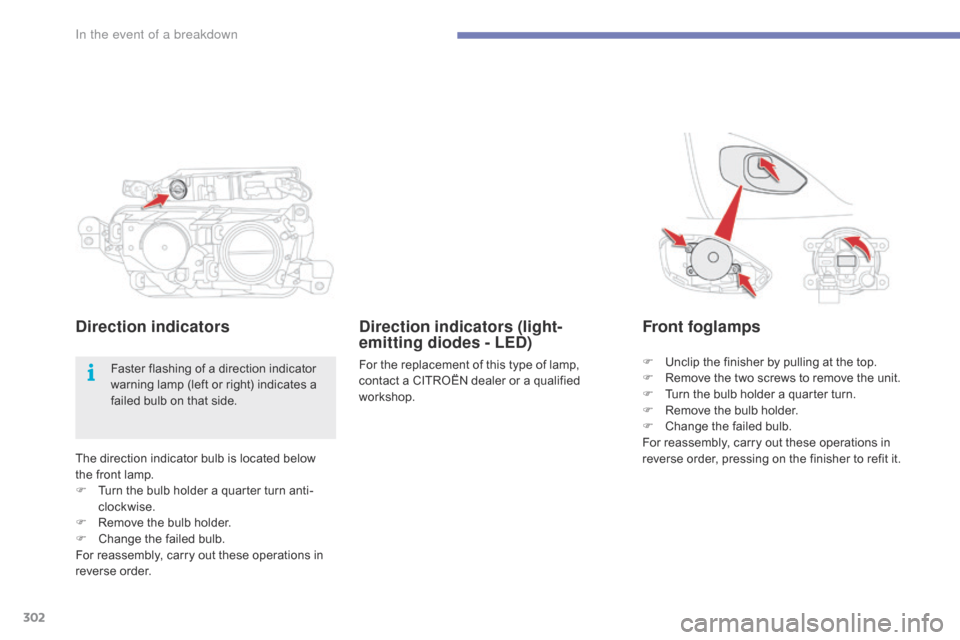
The direction indicator bulb is located below the front lamp.
F
T
urn the bulb holder a quarter turn anti-
clockwise.
F
R
emove the bulb holder.
F
C
hange the failed bulb.
For
reassembly, carry out these operations in
r
everse
o
rder.
Direction indicators Front foglamps
F Unclip the finisher by pulling at the top.
F R emove the two screws to remove the unit.
F
T
urn the bulb holder a quarter turn.
F
R
emove the bulb holder.
F
C
hange the failed bulb.
For
reassembly, carry out these operations in
r
everse order, pressing on the finisher to refit it.
Faster
flashing
of
a
direction
indicator
w
arning
lamp
(left
or
right)
indicates
a
f
ailed
bulb
on
that
side.
Direction indicators (light-
emitting diodes - LED)
For the replacement of this type of lamp, c ontact a CITROËN dealer or a qualified
w
orkshop.
In the event of a breakdown
Page 306 of 523
304
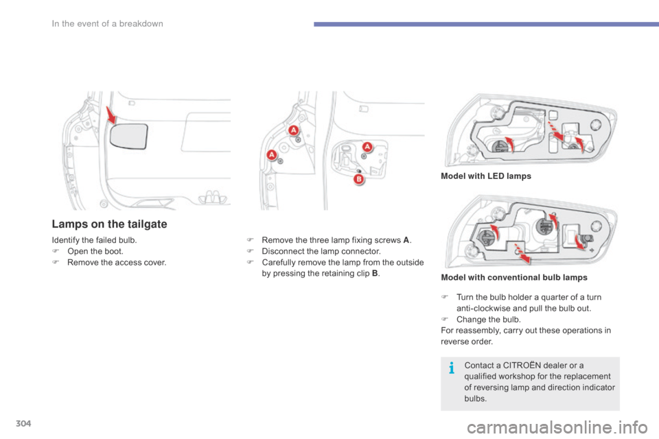
Lamps on the tailgate
Contact a CITROËN dealer or a qualified workshop for the replacement
o
f reversing lamp and direction indicator
b
ulbs.
Identify
the
failed
bulb.
F
O
pen
the
boot.
F
R
emove
the
access
cover.
F
R
emove
the
three
lamp
fixing
screws
A
.
F
D
isconnect
the
lamp
connector.
F
C
arefully
remove
the
lamp
from
the
outside
b
y
pressing
the
retaining
clip
B
.
F
T
urn the bulb holder a quarter of a turn
a
nti-clockwise and pull the bulb out.
F
C
hange the bulb.
For
reassembly, carry out these operations in
r
everse
o
rder.
Model with LED lamps
Model with conventional bulb lamps
In the event of a breakdown
Page 308 of 523
306
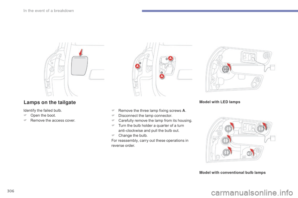
Lamps on the tailgateModel with LED lamps
Model with conventional bulb lamps
Identify
the
failed
bulb.
F
O
pen
the
boot.
F
R
emove
the
access
cover. F
R
emove
the
three
lamp
fixing
screws
A .
F
D
isconnect
the
lamp
connector.
F
C
arefully
r
emove
t
he
l
amp
f
rom
i
ts
h
ousing.
F
T
urn
the
bulb
holder
a
quarter
of
a
turn
a
nti-clockwise
and
pull
the
bulb
out.
F
C
hange
the
bulb.
For
reassembly,
carry
out
these
operations
in
r
everse
o
rder.
In the event of a breakdown
Page 345 of 523
306
In the event of a breakdown
C4-Picasso_II_en_Chap08_en_cas_panne_p306_ed01-2016
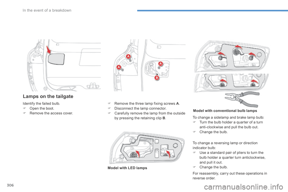
Lamps on the tailgate
For reassembly, carry out these operations in reverse order.
Identify the failed bulb. Open the boot. Remove the access cover.
Remove the three lamp fixing screws A . Disconnect the lamp connector. Carefully remove the lamp from the outside by pressing the retaining clip B .
To change a reversing lamp or direction indicator bulb: Use a standard pair of pliers to turn the bulb holder a quarter turn anticlockwise, and pull it out. Change the bulb. Model with LED lamps
Model with conventional bulb lamps
To change a sidelamp and brake lamp bulb: Turn the bulb holder a quarter of a turn anti-clockwise and pull the bulb out. Change the bulb.