Spanner Citroen XSARA PICASSO 2005 1.G Workshop Manual
[x] Cancel search | Manufacturer: CITROEN, Model Year: 2005, Model line: XSARA PICASSO, Model: Citroen XSARA PICASSO 2005 1.GPages: 462, PDF Size: 10.48 MB
Page 164 of 462
![Citroen XSARA PICASSO 2005 1.G Workshop Manual Downloaded from www.Manualslib.com manuals search engine 158
ENGINE
B1BP234C
XSARA PICASSOAUXILIARY EQUIPMENT DRIVE BELT
Engine: NFV
Without air conditioning
Tools.
[1]Pliers for removing plastic pegs Citroen XSARA PICASSO 2005 1.G Workshop Manual Downloaded from www.Manualslib.com manuals search engine 158
ENGINE
B1BP234C
XSARA PICASSOAUXILIARY EQUIPMENT DRIVE BELT
Engine: NFV
Without air conditioning
Tools.
[1]Pliers for removing plastic pegs](/img/9/4138/w960_4138-163.png)
Downloaded from www.Manualslib.com manuals search engine 158
ENGINE
B1BP234C
XSARA PICASSOAUXILIARY EQUIPMENT DRIVE BELT
Engine: NFV
Without air conditioning
Tools.
[1]Pliers for removing plastic pegs: 7504 -T
[2]Belt tension measuring instrument: 4122 -T
[3] TORX spanner
Remove.
Release the central screw (1), tool[3].
Detension the tensioner roller (2)
(flat spanner 27on flat).
Remove the belt.
Refit.
Position the belt.
Hold the belt in position using the tensioner roller (2).
Pre-tension the belt 120 SEEMunits, tool [2].
Lock the central screw (1)tool [3].
Remove the tool [2].
Rotate the crankshaft 2to 4 times.
Check the tension, 120 SEEMunits.
If not, restart the operation.
Angl.-t2-page135-239-2005 9/01/06 10:14 Page 158
Page 165 of 462
![Citroen XSARA PICASSO 2005 1.G Workshop Manual Downloaded from www.Manualslib.com manuals search engine 159
ENGINE
AUXILIARY EQUIPMENT DRIVE BELT
Engine: NFV
With air conditioning
XSARA PICASSO
B1BP235C
Tools.
[1]Pliers for removing plastic pegs: Citroen XSARA PICASSO 2005 1.G Workshop Manual Downloaded from www.Manualslib.com manuals search engine 159
ENGINE
AUXILIARY EQUIPMENT DRIVE BELT
Engine: NFV
With air conditioning
XSARA PICASSO
B1BP235C
Tools.
[1]Pliers for removing plastic pegs:](/img/9/4138/w960_4138-164.png)
Downloaded from www.Manualslib.com manuals search engine 159
ENGINE
AUXILIARY EQUIPMENT DRIVE BELT
Engine: NFV
With air conditioning
XSARA PICASSO
B1BP235C
Tools.
[1]Pliers for removing plastic pegs: 7504 -T
[2]Belt tension measuring instrument: 4122 -T
[3] 10 mmsquare
(drain spanner)[4] TORX spanner
Remove.
Detension the automatic tensioner, tool [3].
Place a Ø 6 mmpeg at (a)to immobilise the automatic tensioner.
Remove the belt.
Refit.
Position the belt.
Detension the automatic tensioner, tool [3].
Remove the Ø 6 mmpeg.
Release the automatic tensioner.
Remove the tool [3].
Angl.-t2-page135-239-2005 9/01/06 10:14 Page 159
Page 170 of 462
![Citroen XSARA PICASSO 2005 1.G Workshop Manual Downloaded from www.Manualslib.com manuals search engine 164
ENGINE
B1BP39AC
B1BP23RC
AUXILIARY EQUIPMENT DRIVE BELT
Engine: RFK
Tools.
[1]Detensioning lever for auxiliaries drive belt tensioner rolle Citroen XSARA PICASSO 2005 1.G Workshop Manual Downloaded from www.Manualslib.com manuals search engine 164
ENGINE
B1BP39AC
B1BP23RC
AUXILIARY EQUIPMENT DRIVE BELT
Engine: RFK
Tools.
[1]Detensioning lever for auxiliaries drive belt tensioner rolle](/img/9/4138/w960_4138-169.png)
Downloaded from www.Manualslib.com manuals search engine 164
ENGINE
B1BP39AC
B1BP23RC
AUXILIARY EQUIPMENT DRIVE BELT
Engine: RFK
Tools.
[1]Detensioning lever for auxiliaries drive belt tensioner roller:
Dynamic spanner extension: FACOM SJ.214
Adaptor for socket 9x12 : FACOM J.274
Polygon socket 9x12 : 016
Removing.
Raise and support the vehicle, wheels hanging.
Remove the front RH wheel, the plastic pins and the splash-shield.
Turn the tensioner roller(1)by the screw (2)
(anti-clockwise), using tool [1]to detension the belt (3).
NOTE: Screw (2)has a left hand thread.
Remove the auxiliaries drive belt (3).
Refitting.
IMPERATIVE: Check that the rollers (4) and (5) turn freely
(without play and without tight spots).
Refitting.
Compress the tensioner roller (1), using tool [1].
Fit the auxiliaries drive belt (3).
IMPERATIVE: Make sure that the auxiliaries drive belt is correctly positioned in the grooves of
the various pulleys.
Complete the refitting.
Tightening torques:
- Tensioner roller screw (4)tighten to: 2 ± 0,2 m.daN.
- Guide roller screw (5)tighten to: 3,5 ± 0,3 m.daN.
C4
Angl.-t2-page135-239-2005 9/01/06 10:14 Page 164
Page 198 of 462
Downloaded from www.Manualslib.com manuals search engine 192
ENGINECHECKING AND SETTING THE VALVE TIMING
Engine: KFU
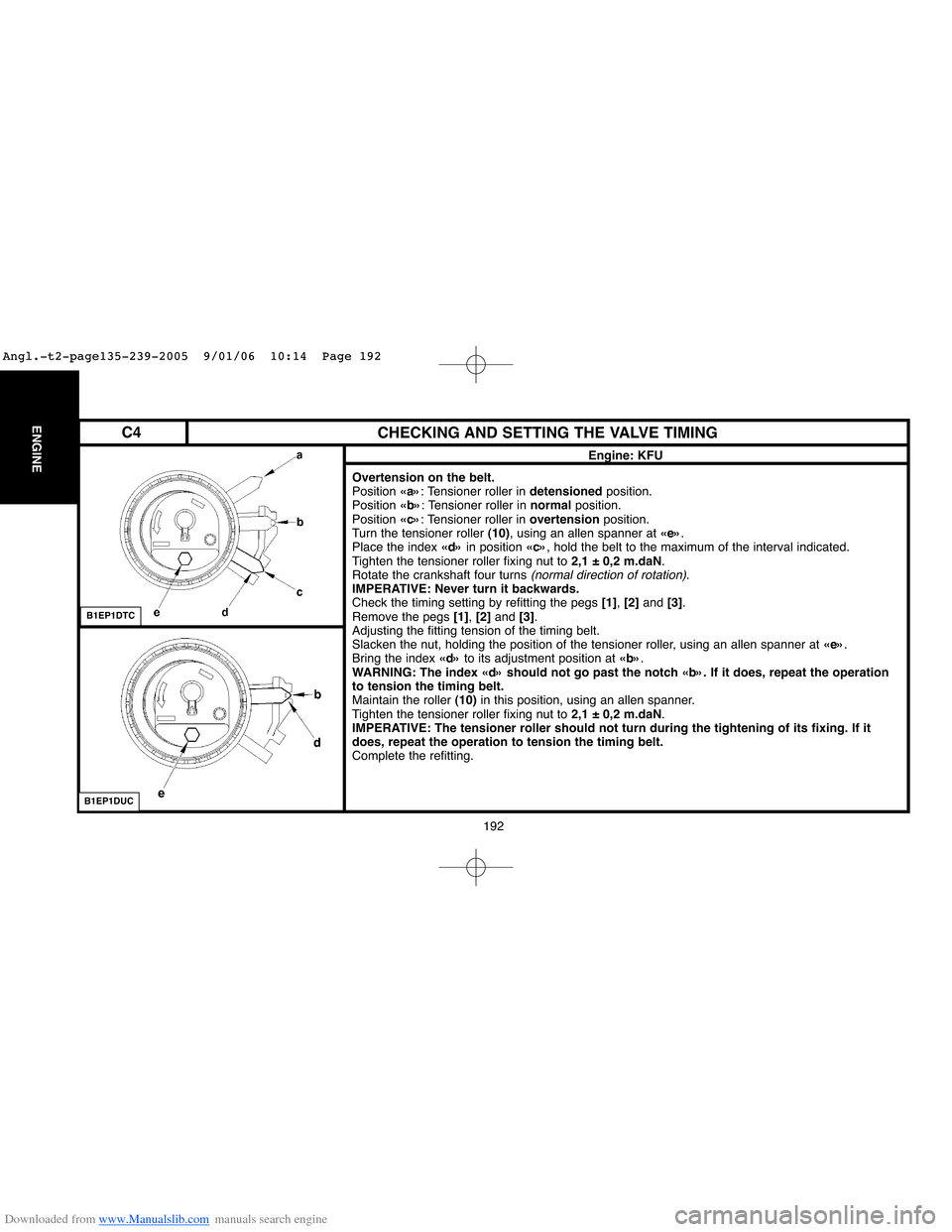
Overtension on the belt.
Position «a»: Tensioner roller in detensionedposition.
Position «b»: Tensioner roller in normalposition.
Position «c»: Tensioner roller in overtensionposition.
Turn the tensioner roller (10), using an allen spanner at «e».
Place the index «d»in position «c», hold the belt to the maximum of the interval indicated.
Tighten the tensioner roller fixing nut to 2,1 ± 0,2 m.daN.
Rotate the crankshaft four turns
(normal direction of rotation).
IMPERATIVE: Never turn it backwards.
Check the timing setting by refitting the pegs [1], [2] and [3].
Remove the pegs [1], [2]and [3].
Adjusting the fitting tension of the timing belt.
Slacken the nut, holding the position of the tensioner roller, using an allen spanner at «e».
Bring the index «d»to its adjustment position at «b».
WARNING: The index «d» should not go past the notch «b». If it does, repeat the operation
to tension the timing belt.
Maintain the roller (10)in this position, using an allen spanner.
Tighten the tensioner roller fixing nut to 2,1 ± 0,2 m.daN.
IMPERATIVE: The tensioner roller should not turn during the tightening of its fixing. If it
does, repeat the operation to tension the timing belt.
Complete the refitting.
B1EP1DTC
B1EP1DUC
C4
Angl.-t2-page135-239-2005 9/01/06 10:14 Page 192
Page 207 of 462
Downloaded from www.Manualslib.com manuals search engine 201
ENGINE
CHECKING AND SETTING THE VALVE TIMING
Engine: NFU
Refitting.
Fit the
(new)timing belt in position, in the following order:
- Inlet camshaft pulley, exhaust camshaft pulley, guide roller, crankshaft pulley, position tool [5],
coolant pump pulley, dynamic tensioner roller.
Remove tools [1], [2a], [2b]and [4].
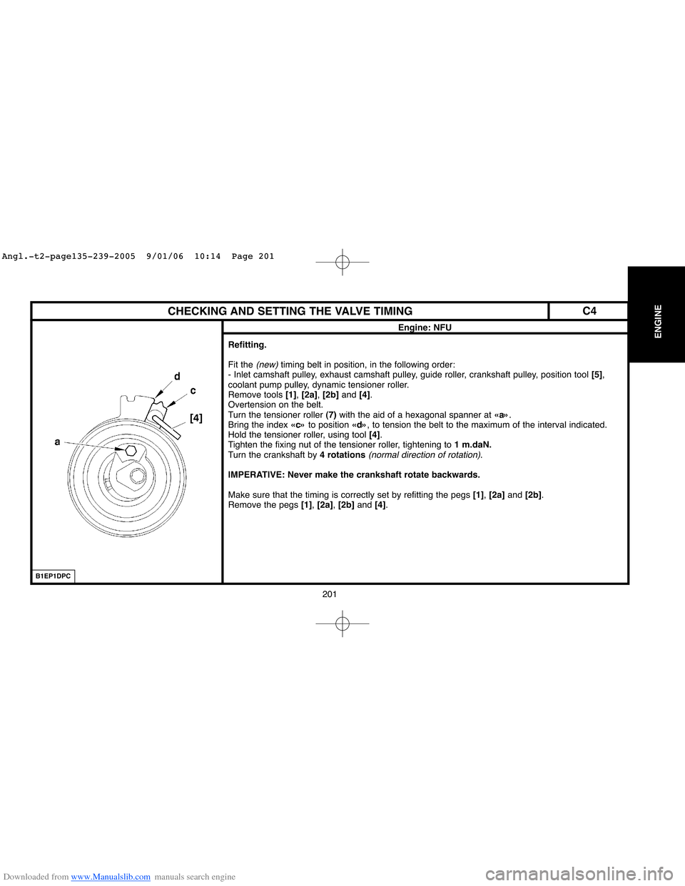
Overtension on the belt.
Turn the tensioner roller (7)with the aid of a hexagonal spanner at «a».
Bring the index «c»to position «d», to tension the belt to the maximum of the interval indicated.
Hold the tensioner roller, using tool [4].
Tighten the fixing nut of the tensioner roller, tightening to 1 m.daN.
Turn the crankshaft by 4 rotations
(normal direction of rotation).
IMPERATIVE: Never make the crankshaft rotate backwards.
Make sure that the timing is correctly set by refitting the pegs [1], [2a]and [2b].
Remove the pegs [1], [2a], [2b]and[4].
B1EP1DPC
C4
Angl.-t2-page135-239-2005 9/01/06 10:14 Page 201
Page 208 of 462
Downloaded from www.Manualslib.com manuals search engine 202
ENGINECHECKING AND SETTING THE VALVE TIMING
Engine: NFU
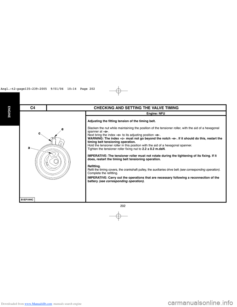
Adjusting the fitting tension of the timing belt.
Slacken the nut while maintaining the position of the tensioner roller, with the aid of a hexagonal
spanner at «a».
Next bring the index «c»to its adjusting position «e».
WARNING: The index «c» must not go beyond the notch «e». If it should do this, restart the
timing belt tensioning operation.
Hold the tensioner roller in this position with the aid of a hexagonal spanner.
Tighten the tensioner roller fixing nut to 2.2 ± 0.2 m.daN.
IMPERATIVE: The tensioner roller must not rotate during the tightening of its fixing. If it
does, restart the timing belt tensioning operation.
Refitting.
Refit the timing covers, the crankshaft pulley, the auxiliaries drive belt
(see corresponding operation).
Complete the refitting.
IMPERATIVE: Carry out the operations that are necessary following a reconnection of the
battery
(see corresponding operation).
B1EP1HHC
C4
Angl.-t2-page135-239-2005 9/01/06 10:14 Page 202
Page 214 of 462
Downloaded from www.Manualslib.com manuals search engine 208
ENGINECHECKING AND SETTING THE VALVE TIMING
Engine: RFJ
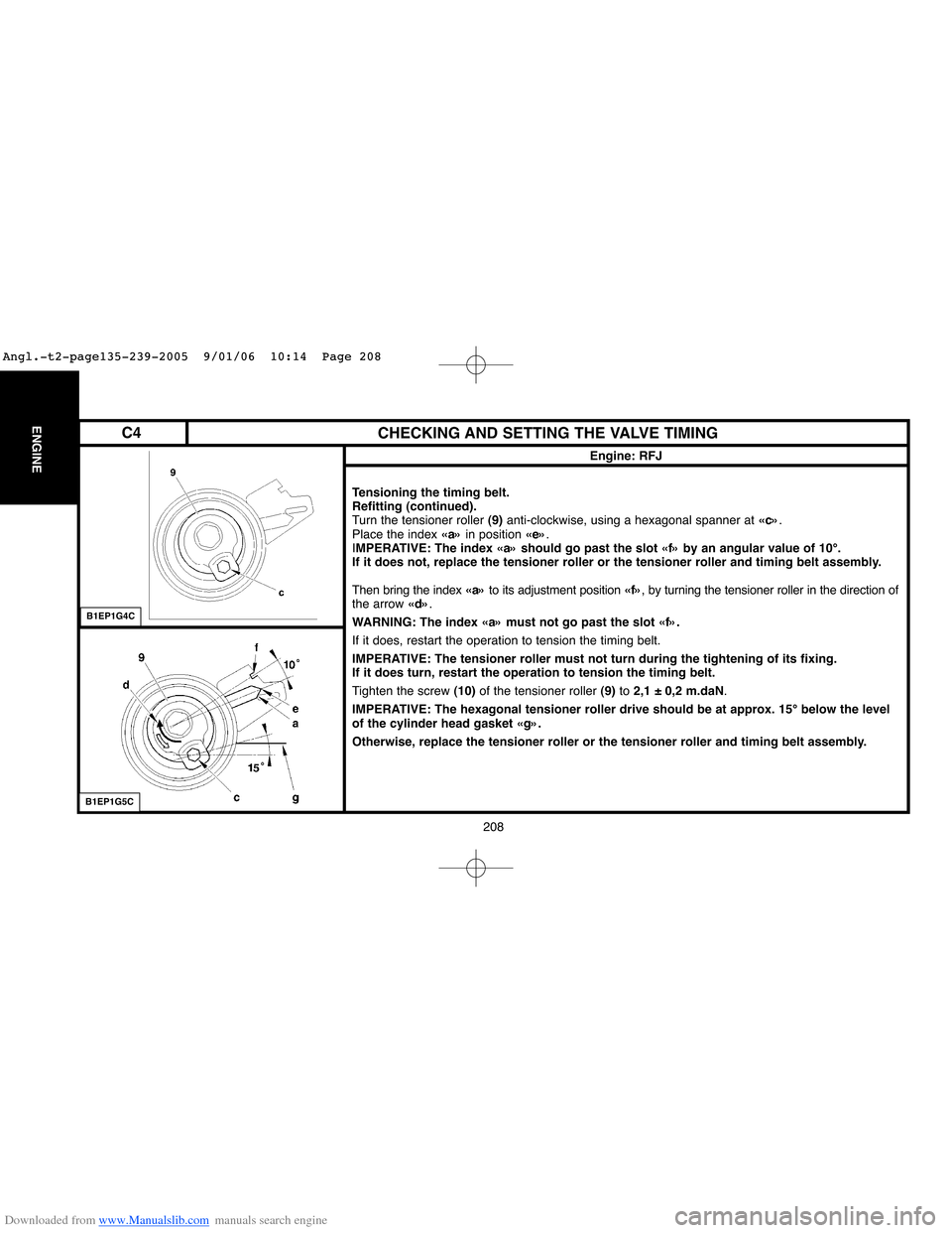
Tensioning the timing belt.
Refitting (continued).
Turn the tensioner roller (9)anti-clockwise, using a hexagonal spanner at «c».
Place the index «a»in position «e».
IMPERATIVE: The index «a» should go past the slot «f» by an angular value of 10°.
If it does not, replace the tensioner roller or the tensioner roller and timing belt assembly.
Then bring the index «a»to its adjustment position «f», by turning the tensioner roller in the direction of
the arrow «d».
WARNING: The index «a» must not go past the slot «f».
If it does, restart the operation to tension the timing belt.
IMPERATIVE: The tensioner roller must not turn during the tightening of its fixing.
If it does turn, restart the operation to tension the timing belt.
Tighten the screw (10)of the tensioner roller (9)to 2,1 ± 0,2 m.daN.
IMPERATIVE: The hexagonal tensioner roller drive should be at approx. 15° below the level
of the cylinder head gasket «g».
Otherwise, replace the tensioner roller or the tensioner roller and timing belt assembly.
B1EP1G4C
B1EP1G5C
C4
Angl.-t2-page135-239-2005 9/01/06 10:14 Page 208
Page 221 of 462
Downloaded from www.Manualslib.com manuals search engine 215
ENGINE
CHECKING AND SETTING THE VALVE TIMING
Engine: RFN
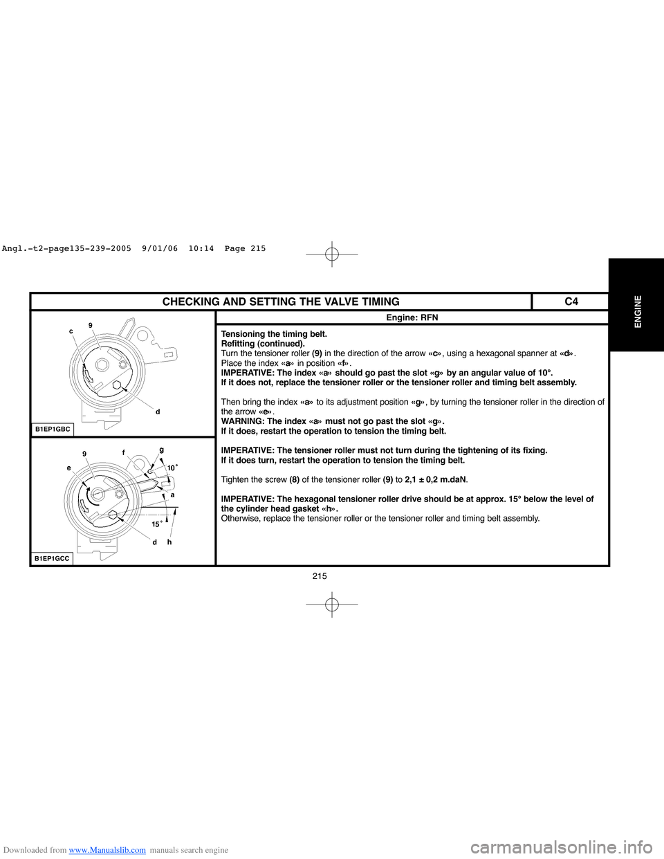
Tensioning the timing belt.
Refitting (continued).
Turn the tensioner roller (9)in the direction of the arrow «c», using a hexagonal spanner at «d».
Place the index «a»in position «f».
IMPERATIVE: The index «a» should go past the slot «g» by an angular value of 10°.
If it does not, replace the tensioner roller or the tensioner roller and timing belt assembly.
Then bring the index «a»to its adjustment position «g», by turning the tensioner roller in the direction of
the arrow «e».
WARNING: The index «a» must not go past the slot «g».
If it does, restart the operation to tension the timing belt.
IMPERATIVE: The tensioner roller must not turn during the tightening of its fixing.
If it does turn, restart the operation to tension the timing belt.
Tighten the screw (8)of the tensioner roller (9)to 2,1 ± 0,2 m.daN.
IMPERATIVE: The hexagonal tensioner roller drive should be at approx. 15° below the level of
the cylinder head gasket «h».
Otherwise, replace the tensioner roller or the tensioner roller and timing belt assembly.
B1EP1GBC
B1EP1GCC
C4
Angl.-t2-page135-239-2005 9/01/06 10:14 Page 215
Page 228 of 462
Downloaded from www.Manualslib.com manuals search engine 222
ENGINECHECKING AND SETTING THE VALVE TIMING
Engines: 6FZ - RFN
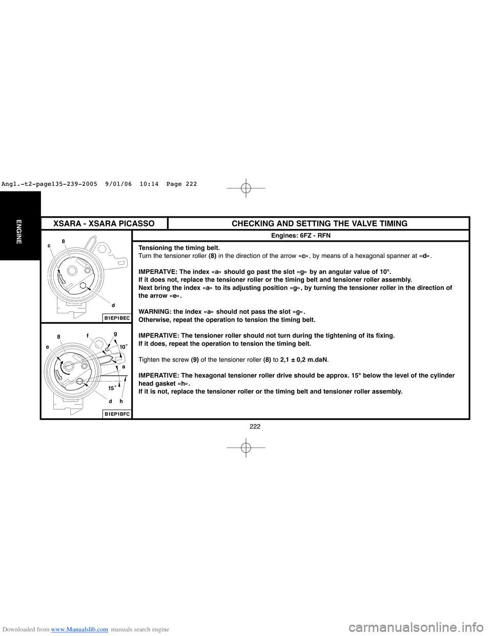
Tensioning the timing belt.
Turn the tensioner roller (8)in the direction of the arrow «c», by means of a hexagonal spanner at «d».
IMPERATVE: The index «a» should go past the slot «g» by an angular value of 10°.
If it does not, replace the tensioner roller or the timing belt and tensioner roller assembly.
Next bring the index «a» to its adjusting position «g», by turning the tensioner roller in the direction of
the arrow «e».
WARNING: the index «a» should not pass the slot «g».
Otherwise, repeat the operation to tension the timing belt.
IMPERATIVE: The tensioner roller should not turn during the tightening of its fixing.
If it does, repeat the operation to tension the timing belt.
Tighten the screw (9)of the tensioner roller (8)to 2,1 ± 0,2 m.daN.
IMPERATIVE: The hexagonal tensioner roller drive should be approx. 15° below the level of the cylinder
head gasket «h».
If it is not, replace the tensioner roller or the timing belt and tensioner roller assembly.
B1EP1BEC
B1EP1BFC
XSARA - XSARA PICASSO
Angl.-t2-page135-239-2005 9/01/06 10:14 Page 222
Page 236 of 462
Downloaded from www.Manualslib.com manuals search engine 230
ENGINECHECKING AND SETTING THE VALVE TIMING
Engine: RFK
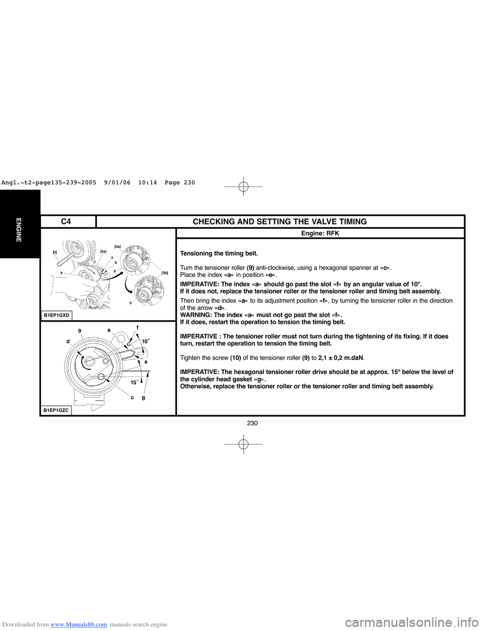
Tensioning the timing belt.
Turn the tensioner roller (9)anti-clockwise, using a hexagonal spanner at «c».
Place the index «a»in position «e».
IMPERATIVE: The index «a» should go past the slot «f» by an angular value of 10°.
If it does not, replace the tensioner roller or the tensioner roller and timing belt assembly.
Then bring the index «a»to its adjustment position «f», by turning the tensioner roller in the direction
of the arrow «d».
WARNING: The index «a» must not go past the slot «f».
If it does, restart the operation to tension the timing belt.
IMPERATIVE : The tensioner roller must not turn during the tightening of its fixing. If it does
turn, restart the operation to tension the timing belt.
Tighten the screw (10)of the tensioner roller (9)to 2,1 ± 0,2 m.daN.
IMPERATIVE: The hexagonal tensioner roller drive should be at approx. 15° below the level of
the cylinder head gasket «g».
Otherwise, replace the tensioner roller or the tensioner roller and timing belt assembly.
B1EP1GXD
B1EP1GZC
C4
Angl.-t2-page135-239-2005 9/01/06 10:14 Page 230