main relay DAEWOO LACETTI 2004 Service Owner's Manual
[x] Cancel search | Manufacturer: DAEWOO, Model Year: 2004, Model line: LACETTI, Model: DAEWOO LACETTI 2004Pages: 2643, PDF Size: 80.54 MB
Page 349 of 2643

ENGINE CONTROLS 1F – 103
DAEWOO V–121 BL4
StepNo Yes Value(s) Action
20Check the wire between the cooling fan control relay
connector terminal 87A and the auxiliary cooling fan
connector terminal 2 for an open.
Is the problem found?–Go to Step 22Go to Step 21
21Check for an open wire between the auxiliary cooling
fan connector terminal 1 and ground.
Is the problem found?–Go to Step 22Go to Step 29
22Repair the open wire as needed.
Is the repair complete?–System OK–
23Repair the open between the cooling fan relay Low
connector terminal 30 and the fuse Ef21.
Is the repair complete?–System OK–
24Repair the open between the cooling fan relay Low
connector terminal 86 and the ignition switch.
Is the repair complete?–System OK–
25Repair the open wire between the cooling fan relay
Low connector terminal 85 and the ECM connector
terminal K28.
Is the repair complete?–System OK–
26Replace the cooling fan relay Low.
Is the repair complete?–System OK–
27Replace the cooling fan control relay.
Is the repair complete?–System OK–
28Replace the main cooling fan.
Is the repair complete?–System OK–
29Replace the auxiliary cooling fan.
Is the repair complete?–System OK–
30Replace the ECM.
Is the repair complete?–System OK–
311. Turn the ignition OFF.
2. Disconnect the main cooling fan connector.
3. Connect a test light between the main cooling
fan connector termina 2 and ground.
4. Turn the A/C switch ON.
5. Start the engine.
Is the test light on?–Go to Step 32Go to Step 12
321. Turn the ignition OFF.
2. Connect a test light between the main cooling
fan connector terminal 1 and battery positive.
3. Turn the A/C switch ON.
4. Start the engine.
Is the test light on?–Go to Step 28Go to Step 17
331. Turn the ignition OFF.
2. Disconnect the cooling fan relay Hi.
3. Connect a test light between the cooling fan
relay Hi connector terminal 86 and ground.
4. Turn the ignition ON.
Is the test light on?–Go to Step 34Go to Step 44
Page 350 of 2643

1F – 104IENGINE CONTROLS
DAEWOO V–121 BL4
StepNo Yes Value(s) Action
341. Turn the ignition OFF.
2. Connect a test light between the cooling fan
relay Hi connector terminal 30 and ground.
Is the test light on?–Go to Step 35Go to Step 45
351. Disconnect the cooling fan control relay.
2. Connect a test light between the cooling fan
control relay connector terminal 85 and ground.
3. Turn the ignition ON.
Is the test light on?–Go to Step 36Go to Step 46
361. Turn the ignition OFF.
2. Connect a test light between the cooling fan
control relay connector terminal 87 and battery
positive.
Is the test light on?–Go to Step 37Go to Step 47
371. Connect the main cooling fan connector.
2. Connect the cooling fan relay Hi.
3. Connect the cooling fan control relay.
4. Disconnect the ECM connector.
5. Connect a fused jumper between the ECM
connector terminal K28 and ground.
6. Connect a fused jumper between the ECM
connector terminal K12 and ground.
7. Turn the ignition ON.
Do the cooling fans run at high speed?–Go to Step 30Go to Step 38
381. Turn the ignition OFF.
2. Check for an open wire between the cooling
fan relay Hi connector terminal 85 and the
ECM connector terminal K12.
Is the problem found?–Go to Step 22Go to Step 39
391. Disconnect the cooling fan relay Hi.
2. Connect a test light between the cooling fan
relay Hi connector terminal 87 and battery posi-
tive.
Is the test light on?–Go to Step 40Go to Step 48
401. Disconnect the ECM connector.
2. Connect a fused jumper between the ECM
connector terminal K12 and ground.
3. Disconnect the cooling fan relay Hi.
4. Connect a test light between the cooling fan
control relay connector terminal 86 and battery
positive.
Is the test light on?–Go to Step 41Go to Step 49
Page 359 of 2643

ENGINE CONTROLS 1F – 113
DAEWOO V–121 BL4
DTCIlluminate MIL Error
Type Function
P1321Crankshaft Segment Period Tooth ErrorEYES
P1382Rough Road Data Invalid (Non ABS)CnlNO
P1382Rrough Road Data Invalid (ABS)CnlNO
P1385Rough Road Sensor Circuit Fault (Non ABS)CnlNO
P1402Exhaust Gas Recirculation BlockedEYES
P1403Exhaust Gas Recirculation Valve FailureEYES
P1404Exhaust Gas Recirculation (EGR) ClosedEYES
P1511Idle Charge Actuactor Circuit FaultEYES
P1512Idle Charge Actuactor Mechanical ErrorEYES
P1513Idle Charge Actuactor Functionnal ErrorCnlNO
P1537A/C Compressor Relay High VoltageCnlNO
P1538A/C Compressor Relay Low VoltageCnlNO
P1610Main Relay High Voltage (1.4L DOHC)CnlNO
P1610Main Relay High Voltage (1.6L DOHC)AYES
P1611Main Relay Low Voltage (1.4L DOHC)CnlNO
P1611Main Relay Low Voltage (1.6L DOHC)AYES
P1628Immobilizer No Successful CommunicationCnlNO
P1629Immobilizer Wrong ComputationCnlNO
P1660Malfunction Indicator Lamp(MIL) High VoltageEYES
P1661Malfunction Indicator Lamp(MIL) Low VoltageEYES
Page 480 of 2643

1F – 234IENGINE CONTROLS
DAEWOO V–121 BL4
StepNo Yes Value(s) Action
51. Repair the line break in the wire between the
EVAP canister purge valve connector 1 and the
main relay connector terminal 65.
2. Clear any Diagnostic Trouble Codes (DTCs)
from the ECM.
3. Perform the diagnostic system check.
Is the repair complete?–System OK–
61. Replace the ECM.
2. Perform the diagnostic system check.
Is the repair complete?–Go to Step 7–
71. Using the scan tool, clear the Diagnostic
Trouble Codes (DTCs).
2. Start the engine and idle at normal operating
temperature.
3. Operate the vehicle within the Conditions for
setting this DTC as specified in the supporting
text.
Does the scan tool indicate that this diagnostic has
run and passed?–Go to Step 8Go to Step 2
8Check if any additional DTCs are set.
Are any DTCs displayed that have not been diag-
nosed?–Go to
Applicable DTC
tableSystem OK
Page 516 of 2643

1F – 270IENGINE CONTROLS
DAEWOO V–121 BL4
DIAGNOSTIC TROUBLE CODE (DTC) P0562
SYSTEM VOLTAGE(ENGINE SIDE) TOO LOW
Circuit Description
The engine control module (ECM) monitors the ignition
voltage on the ignition feed circuit to terminal 29 at the
ECM. A system voltage Diagnostic Trouble Code (DTC)
will set whenever the voltage is below a calibrated value.
Conditions for Setting the DTC
S The main relay voltage is less than 5.0v or higher
than 16.6v during 7.65 seconds. (1.4L DOHC)
S The main relay voltage is less than 5.0v or higher
than 26v during 7.6 seconds. (1.6L DOHC)
Action Taken When the DTC Sets
S The Malfunction Indicator Lamp (MIL) will not illumi-
nate.
S The ECM will store conditions which were present
when the DTC was set as Failure Records data
only.
S This information will not be stored in the Freeze
Frame data.Conditions for Clearing the MIL/DTC
S A history DTC will clear after 40 consecutive warm–
up cycles without a fault.
S DTC(s) can be cleared by using the scan tool.
S Disconnecting the ECM battery feed for more than
10 seconds.
Diagnostic Aids
An Intermittent problem may be caused by a poor connec-
tion, rubbed through wire insulation, or wire that is broken
inside the insulation.
Any circuitry, that is suspected as causing the complaint,
should be thoroughly checked for the following conditions.
S Backed–out terminals
S Improper mating
S Broken locks
S Improperly formed
S Damaged terminals
S Poor terminal to wiring connections
S Physical damage to the wiring harness
Page 518 of 2643

1F – 272IENGINE CONTROLS
DAEWOO V–121 BL4
DIAGNOSTIC TROUBLE CODE (DTC) P0563
SYSTEM VOLTAGE(ENGINE SIDE) TOO HIGH
Circuit Description
The engine control module (ECM) monitors the ignition
voltage on the ignition feed circuit to terminal 29 at the
ECM. A system voltage Diagnostic Trouble Code (DTC)
will set whenever the voltage is below a calibrated value.
Conditions for Setting the DTC
S The main relay voltage is greater than 7.9V.
Action Taken When the DTC Sets
S The Malfunction Indicator Lamp (MIL) will not illumi-
nate.
S The ECM will store conditions which were present
when the DTC was set as Failure Records data
only.
S This information will not be stored in the Freeze
Frame data.
Conditions for Clearing the MIL/DTCS A history DTC will clear after 40 consecutive warm–
up cycles without a fault.
S DTC(s) can be cleared by using the scan tool.
S Disconnecting the ECM battery feed for more than
10 seconds.
Diagnostic Aids
An Intermittent problem may be caused by a poor connec-
tion, rubbed through wire insulation, or wire that is broken
inside the insulation.
Any circuitry, that is suspected as causing the complaint,
should be thoroughly checked for the following conditions.
S Backed–out terminals
S Improper mating
S Broken locks
S Improperly formed
S Damaged terminals
S Poor terminal to wiring connections
S Physical damage to the wiring harness
Page 574 of 2643
1F – 328IENGINE CONTROLS
DAEWOO V–121 BL4
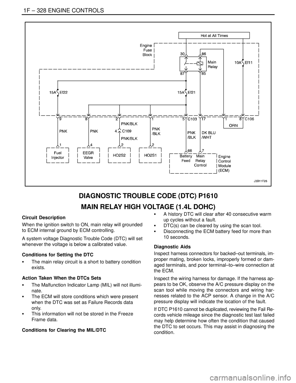
DIAGNOSTIC TROUBLE CODE (DTC) P1610
MAIN RELAY HIGH VOLTAGE (1.4L DOHC)
Circuit Description
When the ignition switch to ON, main relay will grounded
to ECM internal ground by ECM controlling.
A system voltage Diagnostic Trouble Code (DTC) will set
whenever the voltage is below a calibrated value.
Conditions for Setting the DTC
S The main relay circuit is a short to battery condition
exists.
Action Taken When the DTCs Sets
S The Malfunction Indicator Lamp (MIL) will not illumi-
nate.
S The ECM will store conditions which were present
when the DTC was set as Failure Records data
only.
S This information will not be stored in the Freeze
Frame data.
Conditions for Clearing the MIL/DTCS A history DTC will clear after 40 consecutive warm
up cycles without a fault.
S DTC(s) can be cleared by using the scan tool.
S Disconnecting the ECM battery feed for more than
10 seconds.
Diagnostic Aids
Inspect harness connectors for backed–out terminals, im-
proper mating, broken locks, improperly formed or dam-
aged terminals, and poor terminal–to–wire connection at
the ECM.
Inspect the wiring harness for damage. If the harness ap-
pears to be OK, observe the A/C pressure display on the
scan tool while moving the connectors and wiring har-
nesses related to the ACP sensor. A change in the A/C
pressure display will indicate the location of the fault.
If DTC P1610 cannot be duplicated, reviewing the Fail Re-
cords vehicle mileage since the diagnostic test last failed
may help determine how often the condition that caused
the DTC to set occurs. This may assist in diagnosing the
condition.
Page 575 of 2643

ENGINE CONTROLS 1F – 329
DAEWOO V–121 BL4
DTC P1610 – Main Relay High Voltage (1.4L DOHC)
StepActionValue(s)YesNo
1Perform an On–Board Diagnostic (EOBD) System
Check.
Is the system check complete?–Go to Step 2Go to
”On–Board
Diagnostic Sys-
tem Check”
21. Disconnect the main relay.
2. Measure the resistance between main relay
terminals 85 and 86.
Does the resistance within the specified value?75~85WGo to Step 3Go to Step 6
31. Turn the ignition switch to LOCK.
2. With the test light, connected to ground, probe
the ignition feed circuit, at terminal 85 in the
relay harness connector.
Does the test light illuminate?–Go to Step 4Go to
”Diagnostic
Aids”
41. Turn the ignition switch to LOCK.
2. Disconnect the ECM wiring harness connector.
3. With the test light, connected to ground, probe
the ignition feed circuit, at terminal 85 in the
relay harness connector.
Does the test light illuminate?–Go to Step 5Go to Step 7
5Repair a high voltage between the ECM wiring con-
nector terminal 7 and main relay terminal 85.
Is the repair complete?–Go to Step 7–
6Replace the main relay.
Is the replacement complete?–Go to Step 7–
71. Using the scan tool, clear the Diagnostic
Trouble Codes(DTCs).
2. Start the engine and idle at normal operating
temperature.
3. Operate the vehicle within the conditions for
setting this DTC as specified in the supporting
text.
Does the scan tool indicate that this diagnostic has
run and passed?–Go to Step 8Go to Step 2
8Check if any additional DTCs are set.
Are any DTCs displayed that have not been diag-
nosed?–Go to
applicable DTC
tableSystem OK
Page 576 of 2643
1F – 330IENGINE CONTROLS
DAEWOO V–121 BL4
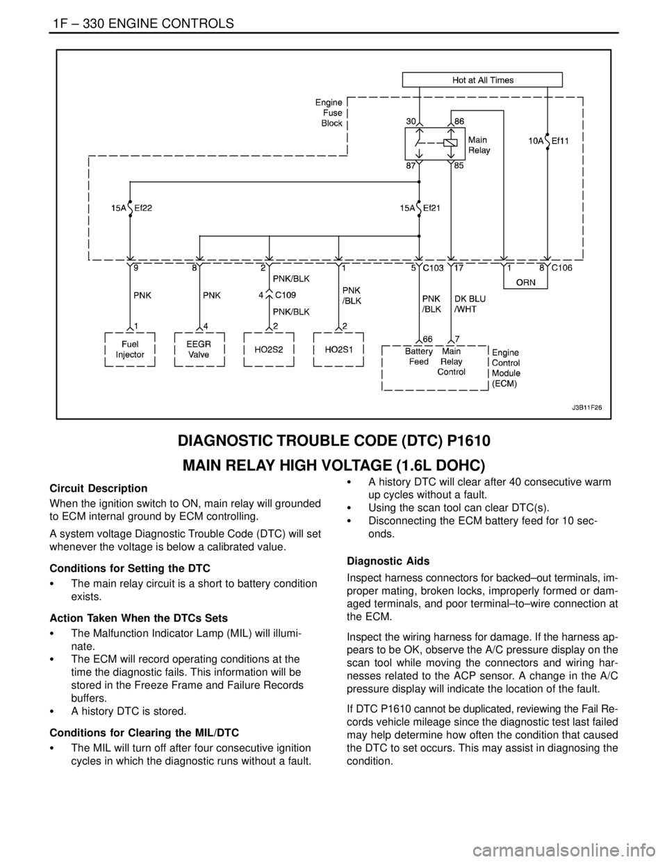
DIAGNOSTIC TROUBLE CODE (DTC) P1610
MAIN RELAY HIGH VOLTAGE (1.6L DOHC)
Circuit Description
When the ignition switch to ON, main relay will grounded
to ECM internal ground by ECM controlling.
A system voltage Diagnostic Trouble Code (DTC) will set
whenever the voltage is below a calibrated value.
Conditions for Setting the DTC
S The main relay circuit is a short to battery condition
exists.
Action Taken When the DTCs Sets
S The Malfunction Indicator Lamp (MIL) will illumi-
nate.
S The ECM will record operating conditions at the
time the diagnostic fails. This information will be
stored in the Freeze Frame and Failure Records
buffers.
S A history DTC is stored.
Conditions for Clearing the MIL/DTC
S The MIL will turn off after four consecutive ignition
cycles in which the diagnostic runs without a fault.S A history DTC will clear after 40 consecutive warm
up cycles without a fault.
S Using the scan tool can clear DTC(s).
S Disconnecting the ECM battery feed for 10 sec-
onds.
Diagnostic Aids
Inspect harness connectors for backed–out terminals, im-
proper mating, broken locks, improperly formed or dam-
aged terminals, and poor terminal–to–wire connection at
the ECM.
Inspect the wiring harness for damage. If the harness ap-
pears to be OK, observe the A/C pressure display on the
scan tool while moving the connectors and wiring har-
nesses related to the ACP sensor. A change in the A/C
pressure display will indicate the location of the fault.
If DTC P1610 cannot be duplicated, reviewing the Fail Re-
cords vehicle mileage since the diagnostic test last failed
may help determine how often the condition that caused
the DTC to set occurs. This may assist in diagnosing the
condition.
Page 577 of 2643

ENGINE CONTROLS 1F – 331
DAEWOO V–121 BL4
DTC P1610 – Main Relay High Voltage (1.6L DOHC)
StepActionValue(s)YesNo
1Perform an On–Board Diagnostic (EOBD) System
Check.
Is the system check complete?–Go to Step 2Go to
”On–Board
Diagnostic Sys-
tem Check”
21. Disconnect the main relay.
2. Measure the resistance between main relay
terminals 85 and 86.
Does the resistance within the specified value?75~85WGo to Step 3Go to Step 6
31. Turn the ignition switch to LOCK.
2. With the test light, connected to ground, probe
the ignition feed circuit, at terminal 85 in the
relay harness connector.
Does the test light illuminate?–Go to Step 4Go to
”Diagnostic
Aids”
41. Turn the ignition switch to LOCK.
2. Disconnect the ECM wiring harness connector.
3. With the test light, connected to ground, probe
the ignition feed circuit, at terminal 85 in the
relay harness connector.
Does the test light illuminate?–Go to Step 5Go to Step 7
5Repair a high voltage between the ECM wiring con-
nector terminal 7 and main relay terminal 85.
Is the repair complete?–Go to Step 7–
6Replace the main relay.
Is the replacement complete?–Go to Step 7–
71. Using the scan tool, clear the Diagnostic
Trouble Codes(DTCs).
2. Start the engine and idle at normal operating
temperature.
3. Operate the vehicle within the conditions for
setting this DTC as specified in the supporting
text.
Does the scan tool indicate that this diagnostic has
run and passed?–Go to Step 8Go to Step 2
8Check if any additional DTCs are set.
Are any DTCs displayed that have not been diag-
nosed?–Go to
applicable DTC
tableSystem OK