stop start DAEWOO LACETTI 2004 Service Owner's Manual
[x] Cancel search | Manufacturer: DAEWOO, Model Year: 2004, Model line: LACETTI, Model: DAEWOO LACETTI 2004Pages: 2643, PDF Size: 80.54 MB
Page 1395 of 2643

5A1 – 46IZF 4 HP 16 AUTOMATIC TRANSAXLE
DAEWOO V–121 BL4
sible, drive the vehicle for a few kilometers (N–D,
N–R, shift until two gear). This will allow the trans-
axle to be within the correct temperature range.
Transaxle fluid level should be checked at tempera-
ture 20 to 45°C (68 to 113°F).
CAUTION : Removal of the fluid filler plug when the
transaxle fluid is hot may cause injury if fluid drains
from the filler hole.
2. Switch off accessories, especially air conditioner,
heater.
3. With the brake pedal pressed, move the gear shift
control lever through the gear ranges, pausing a
few seconds in each range. Return the gearshift
lever to P(Park). Turn the engine OFF.
4. Park the vehicle on a hoist, inspection pit or similar
raised level surface. The vehicle must be level to
obtain a correct fluid level measurement.
5. Place a fluid container below the fluid filler plug.
6. Clean all dirt from around the fluid filler plug.
Remove the fluid filler plug. Clean the filler plug and
check that there is no damage to the ”O” ring.
S If fluid drains through the filler hole the transaxle
may have been overfilled. When the fluid stops
draining the fluid level is correct. Install the fluid
filler plug and tighten it to 45NSm(34 lb–ft).
S If fluid does not drain through the filler hole, the
transaxle fluid level may be low. Lower the ve-
hicle, and start the vehicle in P(Park) with the
parking brake and the brake applied. With the
engine idling, move the gear shift lever through
the gear ranges, pausing a few seconds in each
range and adding the fluid until gear application
is felt. Return the gear shift lever to P(Park).
Turn the engine OFF and raise the vehicle.
Check if the fluid level is aligned with the bottom
of the filler hole. If not, add a small quantity of
fluid to the correct level. Install the fluid filler
plug and tighten it to 45NSm(34 lb–ft).
7. When the fluid level checking procedure is com-
pleted, wipe any fluid around the filler plug with a
rag or shop towel.
Fluid Level Set After Service
1. Depending on the service procedure performed,
add the following amounts of fluid through the filler
plug hole prior to adjusting the fluid level:
Oil pan removal – 4 liters (4.23 quarts)
Converter removal – 2 liters ( 2.11 quarts)
Overhaul – 6.9liters (7.3 quarts)
Oil drain plug removal – 4 liters (4.23 quarts)
2. Follow steps 1 through 4 of the Fluid Level Diagno-
sis Procedure.
3. Clean all dirt from around the fluid filler plug.
Remove the fluid filler plug. Clean the filler plug and
check that there is no damage to the ”O” ring.
4. Lower the vehicle with the filler plug still removed
and start the vehicle in P(Park) with the parking
brake and the brake applied. With the engine idling,move the gear shift lever through the gear ranges,
pausing a few seconds in each range and adding
the fluid until gear application is felt. Then add an
additional 0.5 liters of fluid. Return the gear shift
lever to P(Park). Turn the engine OFF and raise the
vehicle. Install the fluid filler plug and tighten it to
45NSm (34 lb–ft).
5. Drive the vehicle at 2.2 miles(3.5km) to 2.8
miles(4.5 km) with light throttle so that the engine
does not exceed 2500 rpm. This should result in
the transaxle temperature being in the range 20 to
45°C (68 to 11°F). With the brake applied, move
the shift lever through the gear ranges, pausing a
few seconds in each range at the engine idling.
6. Return the gear shift lever to P(Park). Turn the en-
gine OFF and raise the vehicle on the hoist, if appli-
cable, ensuring the vehicle is level. When the three
minutes passed after the engine stopped, remove
the filler plug. Check if the fluid level is aligned with
the bottom of the filler hole. If not, add a small
quantity of fluid to the correct level. Install the fluid
filler plug and tighten it to 45NSm (34 lb–ft).
7. Wipe any fluid around the filler plug with a rag or
shop towel.
Fluid Leak Diagnosis and Repair
The cause of most external leaks can generally be Lo-
cated and repaired with the transaxle in the vehicle.
Methods for Locating Leaks
General Method
1. Verify that the leak is transaxle fluid.
2. Thoroughly clean the suspected leak area.
3. Drive the vehicle for approximately 25 km (15
miles) or until the transaxle reaches normal operat-
ing temperature (88°C, 190°F).
4. Park the vehicle over clean paper or cardboard.
5. Turn the engine OFF and look for fluid spots on the
paper.
6. Make the necessary repairs to correct the leak.
Powder Method
1. Thoroughly clean the suspected leak area.
2. Apply an aerosol type powder (foot powder) to the
suspected leak area.
3. Drive the vehicle for approximately 25 km (15
miles) or until the transaxle reaches normal operat-
ing temperature (88°C, 190°F).
4. Turn the engine OFF.
5. Inspect the suspected leak area and trace the leak
path through the powder to find the source of the
leak.
6. Make the necessary repairs.
Dye and Black Light Method
1. Add dye to the transaxle though the transaxle fluid
filler plug. Follow the manufacturer’s recommenda-
tion for the amount of dye to be used.
2. Use the black light to find the fluid leak.
3. Make the necessary repairs.
Page 1398 of 2643

ZF 4 HP 16 AUTOMATIC TRANSAXLE 5A1 – 49
DAEWOO V–121 BL4
Functional Check Procedure
Inspect
1. Install a tachometer or scan tool.
2. Operate the vehicle unit proper operating tempera-
ture is reached.
3. Drive the vehicle at 80 to 88km/h (50 to 55 mph)
with light throttle(road load).
4. Maintaining throttle position, lightly touch the brake
pedal and check for release of the TCC and a slight
increase in engine speed(rpm).
5. Release the brake slowly accelerate and check for
a reapply of the Lock up clutch and a slight de-
crease in engine speed(rpm).
Torque Converter Evaluation
Torque Converter Stator
The torque converter stator roller clutch can have one of
two different type malfunctions :
A. Stator assembly freewheels in both directions.
B. Stator assembly remains Locked up at all times.
Condition A – Poor Acceleration Low
Speed
The car tends to have poor acceleration from a stand still.
At speeds above 50 to 55km/h(30 to 35mph), the car may
act normal. If poor acceleration is noted, it should first be
determined that the exhaust system is not blocked, and
the transaxle is in 1st(First) gear when starting out.
If the engine freely accelerates to high rpm in N(Neutral),
it can be assumed that the engine and exhaust system are
normal. Checking for poor performance in ”Drive” and ”Re-
verse” will help determine if the stator is freewheeling at all
times.
Condition B – Poor Acceleration High
Speed
Engine rpm and car speed limited or restricted at high
speeds. Performance when accelerating from a standstill
is normal. Engine may overheat. Visual examination of the
converter may reveal a blue color from overheating.
If the converter has been removed, the stator roller clutch
can be checked by inserting two fingers into the splined in-
ner race of the roller clutch and trying to turn freely clock-
wise, but not turn or be very difficult to turn counter clock-
wise.
Noise
Torque converter whine is usually noticed when the ve-
hicle is stopped and the transaxle is in ”Drive” or ”Re-
verse”. The noise will increase when engine rpm is in-
creased. The noise will stop when the vehicle is moving or
when the torque converter clutch is applied because both
halves of the converter are turning at the same speed.
Perform a stall test to make sure the noise is actually com-
ing from the converter :1. Place foot on brake.
2. Put gear selector in ”Drive”.
3. Depress accelerator to approximately 1200rpm for
no more than six seconds.
Notice : If the accelerator is depressed for more than six
seconds, damage to the transaxle may occur.
A torque converter noise will increase under this load.
Important : This noise should not be confused with pump
whine noise which is usually noticeable in P (Park), N
(Neutral) and all other gear ranges. Pump whine will vary
with pressure ranges.
The torque converter should be replaced under any of the
following conditions:
S External leaks in the hub weld area.
S Converter hub is scored or damaged.
S Converter pilot is broken, damaged or fits poorly
into crankshaft.
S Steel particles are found after flushing the cooler
and cooler lines.
S Pump is damaged or steel particles are found in the
converter.
S Vehicle has TCC shudder and/or no TCC apply.
Replace only after all hydraulic and electrical diag-
noses have been made.(Lock up clutch material
may be glazed.)
S Converter has an imbalance which cannot be cor–
rected. (Refer To Converter Vibration Test Proce-
dure.)
S Converter is contaminated with engine coolant con-
taining antifreeze.
S Internal failure of stator roller clutch.
S Excess end play.
S Heavy clutch debris due to overheating (blue con-
verter).
S Steel particles or clutch lining material found in fluid
filter or on magnet when no internal parts in unit are
worn or damaged(indicates that lining material
came from converter).
The torque converter should not be replace if :
S The oil has an odor, is discolored, and there is no
evidence of metal or clutch facing particles.
S The threads in one or more of the converter bolt
holes are damaged.
–correct with thread insert.
S Transaxle failure did not display evidence of dam-
age or worn internal parts, steel particles or clutch
plate lining material in unit and inside the fluid filter.
S Vehicle has been exposed to high mileage(only).
The exception may be where the Lock up clutch
damper plate lining has seen excess wear by ve-
hicles operated in heavy and/or constant traffic,
such as taxi, delivery or police use.
Lock–Up Clutch Shudder Diagnosis
The key to diagnosing lock–up clutch(TCC) shudder is to
note when it happens and under what conditions.
Page 1903 of 2643

6A – 2IPOWER STEERING SYSTEM
DAEWOO V–121 BL4
DIAGNOSIS
POWER STEERING SYSTEM
PRESSURE TEST
Tools Required
KM–354–B Pressure Test Gauge Kit
Check the fluid pressure as follows to determine whether
the trouble is in the pump or the gear unit.
Test Procedure
1. Check the power steering fluid level and the power
steering pump belt tension. Refer to ”Checking and
Adding Fluid” in this section and Section 6B, Power
Steering Pump.
2. Disconnect the high pressure line at the pump. Use
a small container to catch any fluid.
3. Connect the hose of the pressure test gauge kit
KM–354–B to the power steering pressure hose
from the power steering pump.
4. Place the gear selector lever in PARK (automatic
transaxle–equipped vehicles) or NEUTRAL (manual
transaxle–equipped vehicles). Set the parking
brake.
5. Open the gauge valve fully.
6. Start the engine and let it idle.
7. Turn the steering wheel from lock to lock several
times to warm the fluid to operating temperature.
8. Increase the engine speed to 1,500 rpm.
Notice : The power steering pump could be damaged if
the valve is fully closed for more than 5 seconds.
9. Close the gauge valve fully, and read the pressure.
The pump pressure with the valve closed should be
between 8,330 kPa to 8,820 kPa (1,208 psi to
1,279 psi). With electronic variable orifice, the pres-
sure should be between 8,500 kPa to 8,960 kPa
(1,233 psi to 1,299 psi).
10. Immediately open the gauge valve fully.
11. Turn the steering wheel all the way to the left and
the right. If the pressure is within the specified lim-
its, the problem is not in the pump. Check the pow-
er steering gear for leaks.
POWER STEERING SYSTEM LEAK
TEST
General Procedure
Inspect the following:
S The fluid reservoir for overfill.
S Fluid for aeration and overflow.
S The hoses for loose connections.
S The torsion bar, stub shaft and adjuster seals for
leaks.
S The component sealing surfaces for damage.
Important : Verify the exact point of the leak. The point
from which the fluid is dripping is not necessarily the point
at which the system is leaking. When service is required,
clean the leak area upon disassembly, replace the leaking
seal, check the component sealing surfaces for damage
and reset the torque bolt to specifications, where required.
External Leak Check
The purpose of this procedure is to pinpoint the location of
the leak. In some cases, the leak can be easily located, but
seepage–type leaks may be harder to find. To locate seep-
age leaks, use the following method:
1. With the engine off, wipe dry the complete power
steering system.
2. Check the power steering fluid level in the pump’s
reservoir. Adjust the fluid level as necessary. Refer
to ”Checking and Adding Fluid” in this section.
Notice : Do not hold the steering wheel at a stop for any
length of time as this can damage the power steering
pump.
3. Start the engine. Turn the steering wheel counter-
clockwise and clockwise from stop to stop several
times.
4. Find the exact area of the leak and repair it.
Page 1904 of 2643

POWER STEERING SYSTEM 6A – 3
DAEWOO V–121 BL4
MAINTENANCE AND REPAIR
ON–VEHICLE SERVICE
BLEEDING THE POWER STEERING
SYSTEM
If the power steering hydraulic system has been serviced,
an accurate fluid level reading cannot be obtained until the
air is bled from the system. Follow these steps to bleed the
air from the system.
1. Turn the wheels all the way to the left and add the
power steering fluid to the MIN mark on the fluid
level indicator.
Notice : When adding fluid or making a complete fluid
change, always use DEXRON®–II or III power steering
fluid. Failure to use the proper fluid will cause hose and
seal damage and fluid leaks.
2. Start the engine. With the engine running at fast
idle, recheck the fluid level. If necessary, add fluid
to bring the level up to the MIN mark.
3. Bleed the system by turning the wheels from side to
side without reaching the stop at either end. Keep
the fluid level at the MIN mark. The air must be
eliminated from the fluid before normal steering ac-
tion can be obtained.
4. Return the wheels to the center position. Continue
running the engine for 2 to 3 minutes.
5. Road test the car to be sure the steering functions
normally and is free from noise.
6. Recheck the fluid level as described in steps 1 and
2. Make sure the fluid level is at the MAX mark af-
ter the system has stabilized at its normal operating
temperature. Add fluid as needed.
CHECKING AND ADDING FLUID
Notice : When adding fluid or making a complete fluid
change, always use DEXRON®–II or III power steering
fluid. Failure to use the proper fluid will cause hose and
seal damage and fluid leaks.
1. The power steering fluid level is indicated either by
marks on a see–through fluid reservoir or by marks
on a fluid level indicator on the fluid reservoir cap.
2. If the fluid is warmed up to 66°C (150°F), the fluid
level should be between the MAX and MIN marks.
Add fluid as needed.
3. If the fluid is cool, 21°C (70°F), the fluid level
should be at the MIN mark. Add fluid as needed.
Page 1922 of 2643

POWER STEERING GEAR 6C – 5
DAEWOO V–121 BL4
POWER RACK AND PINION
STEERING GEAR BENCH TESTING
Removal, Setup and Testing Procedure
Notice : Pressure checks or pressure and flow checks
may also be conducted using this set–up.
1. Disconnect and remove the power steering gear.
Refer to ”Rack and Pinion Assembly” in this sec-
tion.
2. Place the power steering gear on a bench next to
the vehicle.
3. Disconnect the pressure line at the point where the
hose connects to the pipe. Extend this line in order
to reach the power steering gear on the bench.
4. Disconnect the return line from the the power steer-
ing fluid reservoir. Extend this line in order to reach
the power steering gear on the bench.
5. Connect the power steering pipes to the power
steering gear.6. Start the engine and allow it to idle for 10 seconds.
7. Check the power steering fluid level. Refer to Sec-
tion 6A, Power Steering System.
8. Start the engine and turn the rack and pinion stub
shaft to a full turn in each direction. Hold the shaft
against each stop for 5 seconds.
9. Inspect for possible leak points. Refer to Section
6A, Power Steering System.
Installation Procedure
1. Stop the engine.
2. Disconnect the power steering pipes from the pow-
er steering gear.
3. Remove the extensions and reconnect the pressure
and return lines.
4. Install and connect the power steering gear. Refer
to ”Rack and Pinion Assembly” in this section.
5. Start the engine and stay idle for 10 seconds.
6. Check the power steering fluid level. Refer to Sec-
tion 6A, Power Steering System.
Page 2272 of 2643

9B – 46ILITHING SYSTEMS
DAEWOO V–121 BL4
GENERAL DESCRIPTION
AND SYSTEM OPERATION
HEADLAMPS–ON REMINDER CHIME
When the headlamp switch is in the headlamps–on or
parking lamps–on position, voltage is applied to the chime
module. When the ignition is in ON, ACC or START, volt-
age is applied through the fuse block to the module. These
two voltages are sensed, and the chime module is not
sounded.
When the ignition is not in ON, ACC or START, the module
loses voltage. The chime module senses change. If the
voltage is still available, it is applied to sound the chime.
The chime can be turned off by turning the headlamp
switch off. The module no longer senses voltage from the
headlamp switch, so the chime module does not sound.
HEADLAMPS
The headlamps are controlled by the multifunction lever
located on the left side of the steering column. They will
come on with the ignition switch in any position. Turning
the headlamp switch to the first position turns on the park-
ing lamps, the license plate lamps and the instrument pan-
el illumination. Turning the switch to the second position
turns on all of the previous lamps and the headlamps.
Turning the switch to the OFF position turns off all the
lamps.
Headlamp high beams and low beams are also controlled
by this lever. When the headlamps are on, pushing the le-
ver away from the driver until the switch clicks changes the
lamp from low beam to high beam. An indicator lamp on
the instrument cluster assembly will come on when the
high beam headlamps are on. To return the headlamps to
low beam, pull the lever toward the driver.
The headlamps must be aimed for proper illumination of
the road. Headlamp aim should be checked whenever a
new headlamp assembly is installed, or whenever service
repairs to the front end area may have disturbed the head-
lamp assembly or its mountings.
DAYTIME RUNNING LAMPS
The Daytime Running Lamps (DRL) will come on when:
S The ignition is ON.
S The light is OFF.
S The parking brake is released.
When the exterior lights are on, the DRL will turn off. To
turn the DRL off when idling, apply the parking brake.
PARKING AND TURN SIGNAL LAMPS
The parking lamps can be turned on by turning the lighting
switch to the first position. The parking lamps can be
turned off by turning the switch to the OFF position.When the turn signals are activated, the front and rear turn
signal lamps flash to signal a turn. The turn signals work
only when the ignition is ON.
The turn signals are controlled by the light switch on the
left side of the steering column. Moving the lever all the
way up or down (past the detent) will turn on the front and
rear turn signals. When the turn is completed, the lever will
return to horizontal and the turn signals will stop flashing.
For changing lanes, or for shallow turns in which the steer-
ing wheel does not turn far enough to cancel the signal,
move the signal lever only to the first detent and hold it
there. When the lever is released, it will return to horizontal
and the turn signals will cancel.
FOG LAMPS
The fog lamp switch is on the instrument panel to the right
of the steering column. To use the fog lamps, first turn on
the headlamps or the parking lamps. Then push the fog
lamp switch. The indicator light in the switch will illuminate
to indicate that the fog lamps are on. Push the switch again
to turn off the fog lamps. The indicator light will then go off.
The fog lamps should not be used as a substitute for the
headlamps.
The fog lamps must be aimed for proper illumination of the
road. Fog lamp aim should be checked when a new bulb
is installed or if service or repairs in the front end area may
have disturbed the fog lamp mountings.
REAR COMBINATION LAMPS
The taillamps, stoplamps, turn signal lamps and backup
lamp are one assembly.
Turning on either the headlamps or the parking lamps will
also turn on the taillamps. When the brake pedal is
pushed, the taillamps will glow brighter to serve as sto-
plamps.
The center high–mounted stoplamp is located in the rear
window and will come on when the brake pedal is pressed.
LICENSE PLATE LAMP
The license plate lamps will come on when the headlamps
or the parking lamps are on. The license plate lamps are
mounted above the license plate.
INTERIOR COURTESY LAMP
The courtesy lamp is located on the headliner just behind
the front seats. The lamp switch has three positions. If the
switch is left in the center position, the lamp will go on
whenever a door is opened and go off when it is closed.
In the ON position, the lamp will stay on until it is turned off.
In the OFF position, the lamp will not come on, even when
a door is opened.
LUGGAGE COMPARTMENT LAMP
The luggage compartment lamp is located under the deck
lid sill plate on the notchback. The lamp is located on the
left–side wheelhouse trim panel on the hatchback. It will
come on whenever the luggage compartment is opened.
Page 2621 of 2643
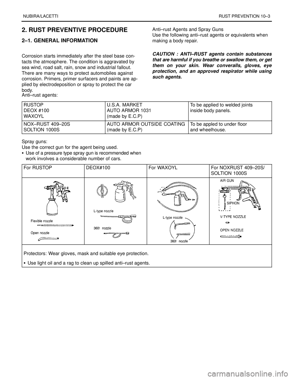
NUBIRA/LACETTIRUST PREVENTION 10–3
2. RUST PREVENTIVE PROCEDURE
2–1. GENERAL INFORMATION
.
Corrosion starts immediately after the steel base con-
tacts the atmosphere. The condition is aggravated by
sea wind, road salt, rain, snow and industrial fallout.
There are many ways to protect automobiles against
corrosion. Primers, primer surfacers and paints are ap-
plied by electrodeposition or spray to protect the car
body.Anti–rust Agents and Spray Guns
Use the following anti–rust agents or equivalents when
making a body repair.
.
CAUTION : ANTI–RUST agents contain substances
that are harmful if you breathe or swallow them, or get
them on your skin. Wear converalls, gloves, eye
protection, and an approved respirator while using
such agents.
.
.
Anti–rust agents:
RUSTOP
DEOX #100
WAXOYL
U.S.A. MARKET
AUTO ARMOR 1031
(made by E.C.P)To be applied to welded joints
inside body panels.
NOX–RUST 409–20S
SOLTION 1000SAUTO ARMOR OUTSIDE COATING
(made by E.C.P)To be appled to under floor
and wheelhouse.
Spray guns:
Use the correct gun for the agent being used.
S Use of a pressure type spray gun is recommended when
work involves a considerable number of cars.
For RUSTOP
DEOX#100For WAXOYLFor NOXRUST 409–20S/
SOLTION 1000S
Protectors: Wear gloves, mask and suitable eye protection.
S Use light oil and a rag to clean up spilled anti–rust agents.