transmission oil DAEWOO LACETTI 2004 Service Owner's Manual
[x] Cancel search | Manufacturer: DAEWOO, Model Year: 2004, Model line: LACETTI, Model: DAEWOO LACETTI 2004Pages: 2643, PDF Size: 80.54 MB
Page 1552 of 2643
ZF 4 HP 16 AUTOMATIC TRANSAXLE 5A1 – 203
DAEWOO V–121 BL4
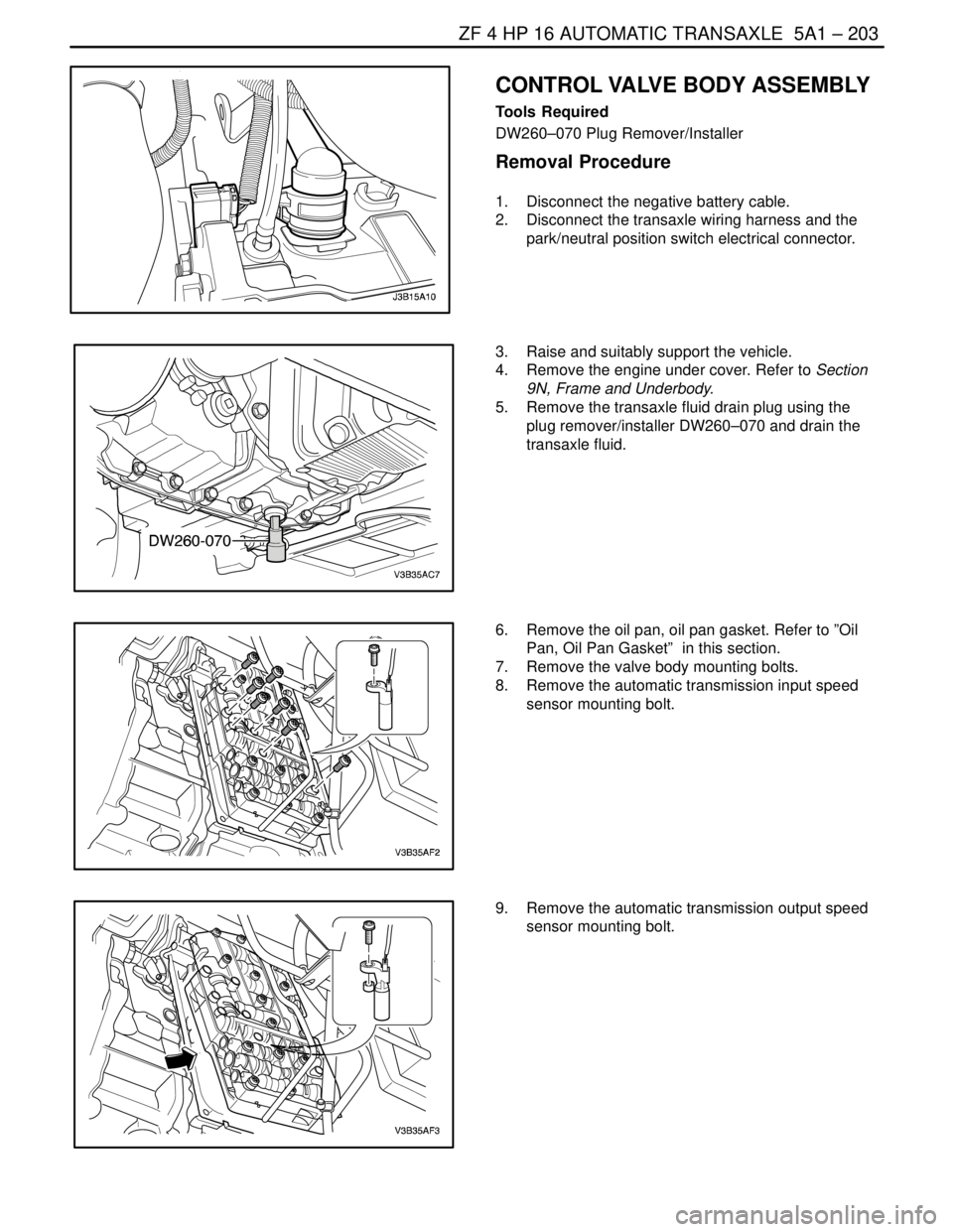
CONTROL VALVE BODY ASSEMBLY
Tools Required
DW260–070 Plug Remover/Installer
Removal Procedure
1. Disconnect the negative battery cable.
2. Disconnect the transaxle wiring harness and the
park/neutral position switch electrical connector.
3. Raise and suitably support the vehicle.
4. Remove the engine under cover. Refer to Section
9N, Frame and Underbody.
5. Remove the transaxle fluid drain plug using the
plug remover/installer DW260–070 and drain the
transaxle fluid.
6. Remove the oil pan, oil pan gasket. Refer to ”Oil
Pan, Oil Pan Gasket” in this section.
7. Remove the valve body mounting bolts.
8. Remove the automatic transmission input speed
sensor mounting bolt.
9. Remove the automatic transmission output speed
sensor mounting bolt.
Page 1592 of 2643
5A2 – 2IAISIN AUTOMATIC TRANSAXLE
DAEWOO V–121 BL4
Shift Control Lever Assembly 5A2–100. . . . . . . . . . . . .
Transmission Range (TR) Switch 5A2–101. . . . . . . . .
Shift Control Cable 5A2–104. . . . . . . . . . . . . . . . . . . . . .
Shift Select Cover 5A2–105. . . . . . . . . . . . . . . . . . . . . .
Input Shaft Speed (ISS) Sensor 5A2–106. . . . . . . . . .
Output Shaft Speed (OSS) Sensor 5A2–107. . . . . . . .
Transmission Control Module (TCM) 5A2–108. . . . . .
Fluid Cooler Inlet Pipes and Hoses 5A2–109. . . . . . . .
Fluid Cooler Outlet Pipes and Hoses 5A2–110. . . . . .
Transaxle Assembly 5A2–111. . . . . . . . . . . . . . . . . . . . .
UNIT REPAIR 5A2–117. . . . . . . . . . . . . . . . . . . . . . . . . . .
Major Component Disassembly 5A2–117. . . . . . . . . . .
Major Component Assembly 5A2–137. . . . . . . . . . . . .
Oil Pump 5A2–167. . . . . . . . . . . . . . . . . . . . . . . . . . . . . . Direct Clutch 5A2–171. . . . . . . . . . . . . . . . . . . . . . . . . . .
Planetary Ring Gear 5A2–178. . . . . . . . . . . . . . . . . . . .
One–Way Clutch 5A2–180. . . . . . . . . . . . . . . . . . . . . . .
Forward and Reverse Clutch 5A2–183. . . . . . . . . . . . .
Counter Driven Gear 5A2–192. . . . . . . . . . . . . . . . . . . .
Valve Body 5A2–195. . . . . . . . . . . . . . . . . . . . . . . . . . . .
Differential Case 5A2–208. . . . . . . . . . . . . . . . . . . . . . . .
GENERAL DESCRIPTION AND SYSTEM
OPERATION5A2–218 . . . . . . . . . . . . . . . . . . . . . . . . . . .
Transaxle Description 5A2–218. . . . . . . . . . . . . . . . . . .
Electronical Components 5A2–218. . . . . . . . . . . . . . . .
Hydraulic Control System 5A2–221. . . . . . . . . . . . . . . .
Automatic Transaxle System 5A2–222. . . . . . . . . . . . .
Page 1594 of 2643

5A2 – 4IAISIN AUTOMATIC TRANSAXLE
DAEWOO V–121 BL4
FASTENER TIGHTENING SPECIFICATIONS
ApplicationNSmLb–FtLb–In
Drain Plug1713–
Control Cable Adjusting Nut8–71
Shift Control Lever Assembly Mounting Bolts8–71
Manual Valve Lever Shaft Nut12–106
Transmission Range (TR) Switch Bolts5.4–48
Input Speed Sensor Retaining Bolt5.4–48
Output Speed Sensor Retaining Bolt7.4–65
TCM Retaining Bolts5–44
Fluid Cooler Inlet Pipe Fitting Nut3526–
Fluid Cooler Inlet Pipe Bolt9–80
Inlet Pipe Union Bolt3526–
Fluid Cooler Rear Outlet Pipe Fitting Nut3526–
Fluid Cooler Rear Outlet Pipe Clip Bolt9–80
Front Outlet Pipe Union Bolt3526–
Lower Transaxle–to–Engine Retaining Bolts (a)7354–
Lower Transaxle–to–Engine Retaining Bolts (b)3123–
Lower Transaxle–to–Engine Retaining Bolts (c)2115–
Upper Transaxle–to–Engine Mounting Bolts7354–
Upper Transaxle Mounting Bracket Bolts6044–
Rear Mounting Bracket Bolts6044–
Damping Block Connection Nut and Bolt8059–
Torque Converter Bolts4543–
Screw Plugs7.4–65
Transaxle Apply Clamp Bolt5.4–48
Oil Reservoir Lock Plate Bolts5.4–48
Transaxle Case Plate Bolt9.8–87
Transaxle Housing Bolts2922–
Manual Detent Spring Bolt9.8–87
Parking Lock Pawl Bracket Bolts7.4–65
Planetary Ring Gear Nut (Standard)9.8–87
Planetary Ring Gear Nut (Maximum)2922–
Transaxle Rear Cover Bolts2518–
Oil Pump Bolts2518–
Valve Body Bolts11–97
Oil Strainer Bolts9.8–87
Oil Pan Bolts7–62
Unions2518–
Stator Shaft Bolts2518–
Shift Solenoid Valve Bolts11–97
Differential Case–to–Differential Ring Gear Bolt10275–
Page 1610 of 2643

5A2 – 20IAISIN AUTOMATIC TRANSAXLE
DAEWOO V–121 BL4
1. Transaxle Housing
2. Oil Seal
3. Oil Reservoir Plate
4. Transaxle Oil Apply Pipe
5. Differential Gear Oil Apply Pipe
6. Transaxle Oil Apply Pipe Clamp
7. Spring
8. Check Valve Pipe Clamp
9. Apply Gasket
10. Brake Drun Gasket
11. Transaxle Wire
12. O–ring
13. Valve Body
14. Parking Lock Pawl
15. Parking Lock Pawl Shaft
16. Torsion Spring
17. Manual Valve lever Shaft
18. Manual Valve Lever
19. Parking Lock Rod
20. Parking Lock Pawl Bracket
21. Manual Detent Spring
22. Pin
23. Spacer24. Oil Seal
25. Transmission Range (TR) Switch
26. Lock Washer
27. Control Lever
28. Washer
29. Gasket
30. Oil Strainer
31. Oil Pan
32. Gasket
33. Magnet
34. Direct Clutch Accumulator Piston
35. O–ring
36. Spring
37. O–ring
38. Forward Clutch Accumulator Piston
39. O–ring
40. Spring
41. O–ring
42. Overdrive Brake Accumulator Piston
43. O–ring
44. O–ring
45. Spring
Page 1709 of 2643

AISIN AUTOMATIC TRANSAXLE 5A2 – 119
DAEWOO V–121 BL4
17. Remove the three bolts and oil strainer.
18. Remove the gasket from the oil strainer.
19. Remove the bolt and transmission fluid temperature
sensor with the clamp.
20. Disconnect the 5 solenoid connectors.
a. Lock–up control solenoid
b. Pressure control solenoid.
c. No.2 shift solenoid.
d. No.1 shift solenoid.
e. Timing solenoid
21. Support the valve body assembly and remove the
14 bolts.
Page 2501 of 2643
IMMOBILIZER ANTI–THEFT SYSTEM 9T2 – 11
DAEWOO V–121 BL4
GENERAL DESCRIPTION
AND SYSTEM OPERATION
IMMOBILIZER SYSTEM
The purpose of the Immobilizer system is to provide addi-
tional theft deterrence to the vehicle in which it is installed
and to prevent it from being stolen or driven by unautho-
rized users.
The verification of the user authorization is done by an igni-
tion key with integrated transponder.
The external LED displays the Immobilizer status and has
an additional theft deterrence function.
To secure the communication, the status is exchanged be-
tween the Immobilizer and the ECM in a 5 byte of encoded
data.
These 5 bytes are composed by a mixture of random data
and two types of fixed code
S a vehicle model identification number : MIN
S a vehicle specific identification : VIN
The MIN is known from the first supply of the system.
The VIN is realized by ICU on the special order from the
key coding (reading of transponder code and storing it as
valid key code in Immobilizer EEPROM).
A different random data is computed at each key transi-
tion.
All the immobilization communication between the ECM
and ICU is made on K–line (K line : Serial data line ’7’).
Due to the learning of the Vehicle specific identification
Number, both ICU and ECM can stay in 3 stable modes
S Virgin mode (VIN not learnt)
S Learnt mode (VIN learnt)
S Neutral mode (for a new VIN learning)
In case of using valid key, the release message commu-
nication with the ECM take place and the LED displays the
Immobilizer status valid key In case of using invalid key,
the ECM disables the fuel injector circuit with coded inter-
vention and sets DTC(Diagnostic Trouble Code)
The above conditions are maintained until the ignition is
switched off.
An ECM without an immobilizer control unit cannot be in-
terchanged for an ECM that is used with an immobilizer
control unit system. The Immobilizer control unit and ECM
must have a matching ID code. ID coding and key coding
are accomplished by using Scanner–100
The Immobilizer system consists of
S a maximum or 5 ignition keys with integrated trans-
ponder
S the toroidal coil (Detection coil) for energizing and
reading the transponder mounted at the ignition
lock.S the Immobilizer control unit(ICU) with :
– power supply
– ignition input circuit
– transponder modulation and demodulation unit
– EEPROM
– driver electronic for the external status LED
– serial data link hardware
S the external status LED for displaying the Immobi-
lizer status
S the serial data link between Immobilizer and ECM
ELECTRONICALLY CODED KEYS
Each valid ignition key has an internal transponder which
is a read /write transponder.
The transponder contains an implementation of a crypto–
algorithm with 96 bits of user configurable s cret–key con-
tained in EEPROM and transmits data to the ICU by mod-
ulating the amplitude of the ele tromagnetic field, and
receives data and commands in a similar way.
DETECTION COIL
The toroidal coil is mounted at the ignition lock in front of
the key barrel.
It is connected to the ICU with a four terminal connector
fixed at the body of the coil.
The length of the connection between coil and Immobilizer
is restricted to 50cm. The correct placement on the ignition
lock and the exact electrical data is very important for the
reading distance of transponder.
he toroidal coil and receiving coil inside the transponder
built a transformer. During the readingprocess the coil in-
duces energy into the transponder. The transponder
charges the field and generates an amplitude modulated
signal with the manchester coded data. This charge of the
field is demodulated inside the Immobilizer.
The Immobilizer contains the coil driver hardware for di-
rect connection of the toroidal coil.
IMMOBILIZER CONTROL UNIT
The function of the Immobilizer System is shared between
the ICU and the ECM.
The task of the Immobilizer Electronic Control unit (ICU)
are:
S Reading of the input information ”ignition ON/OFF”
S Controlling the states LED
S Controlling the transponder read/write process
(modulation, demodulation, decoding, comparison
of the read code with the code of the valid keys).
S Communication with the ECM after ignition ON (re-
ceiving of the ECM–request and transmission of
release message).
S Special functions for calculation and handling of the
VIN–code.
The VIN code is calculated by the Immobilizer using a ran-
dom generator.
Page 2524 of 2643
2–4 PREPARATIONS OF BODYWORK NUBIRA/LACETTI
2. CHECKPOINTS
S Accurate Inspection of Damaged Parts(Visual)
.
Seat Belts
Always replace the seat belt if :
1. The belt material is cut, punctured, burned or in any
way damaged.
2. The buckle or retractor does not work properly.
3. They were being worn at the time of a collision(also
check for damage at the seat belt anchor points).
4. Their condition is questionable.
.
Front Section :
1. Is there any bending, splitting, denting or other dam-
age to the suspension and its related parts?
2. Is there any deformation of the front panel or radiator
crossmember? Have any of the connected sections
come apart?
3. Are there any creases or distortion in the front wheel-
house or side frame? Have any of the connected sec-
tions come apart?
4. Is there any bending or twisting of the whole front
area?
5. Is there any deformation like creases, bulges, or dents
in the front pillar, dash panel, floor, etc.?
6. Is there any vertical twisting or misaligned clearance
in the door?
7. Is the windshield seal broken?
8. Is there any deformation in the vicinity of the top part
of the roof panel’s center pillar?
9. Is there any damage inside the automobile(is there
any twisting of the dash panel, or anything irregular with
the clearances or sheet–mounting parts)?
10. Is there any damage to the steering wheel? Is there
any deformation in the column and the column–mounted
parts?
11. Is there any oil or water leakage and damage to the en-
gine, transmission or brakes?
12. Is there any irregular noise in the gear changing opera-
tion, engine and transmission rotation?
13. Are there any traces of contact between the engine
block and the center crossmember ?
14. Is there any damage to brake or fuel lines, or wire har-
nesses?Rear Section :
1. Is there any twisting, bulging or denting of the rear floor
any rear bolsters? Have any of the connected sections
come apart?
2. Is there any irregular bulging or denting in the rear
fender?
3. Is there any distortion in the rear inner panel? Is there
any bending and denting in the vicinity of the rear pillar?
4. Is there any distortion or creasing is the rear wheel-
house and arch sections? Have any of the connected
sections come apart?
5. Is there anything irregular in the rear glass seal clear-
ance?
6. Is there any twisting or misalignment of the clearance
of the trunk lid opening section?
7. Is there any bending, splitting, denting or other dam-
age to the suspension and its related parts?
8. Is there any deformation of the rear floor crossmem-
ber, trunk floor panel and back panel? Have any of the
connected sections come apart?
.
Impact Beam :
Always replace the door assembly if :
1. The external force makes the impact beam of door in-
ner deform.
Always replace impact beam if :
2. The external force makes the impact beam of front
bumper and rear bumper deform.