water pump DAEWOO LACETTI 2004 Service Owner's Manual
[x] Cancel search | Manufacturer: DAEWOO, Model Year: 2004, Model line: LACETTI, Model: DAEWOO LACETTI 2004Pages: 2643, PDF Size: 80.54 MB
Page 206 of 2643
ENGINE COOLING 1D – 11
DAEWOO V–121 BL4
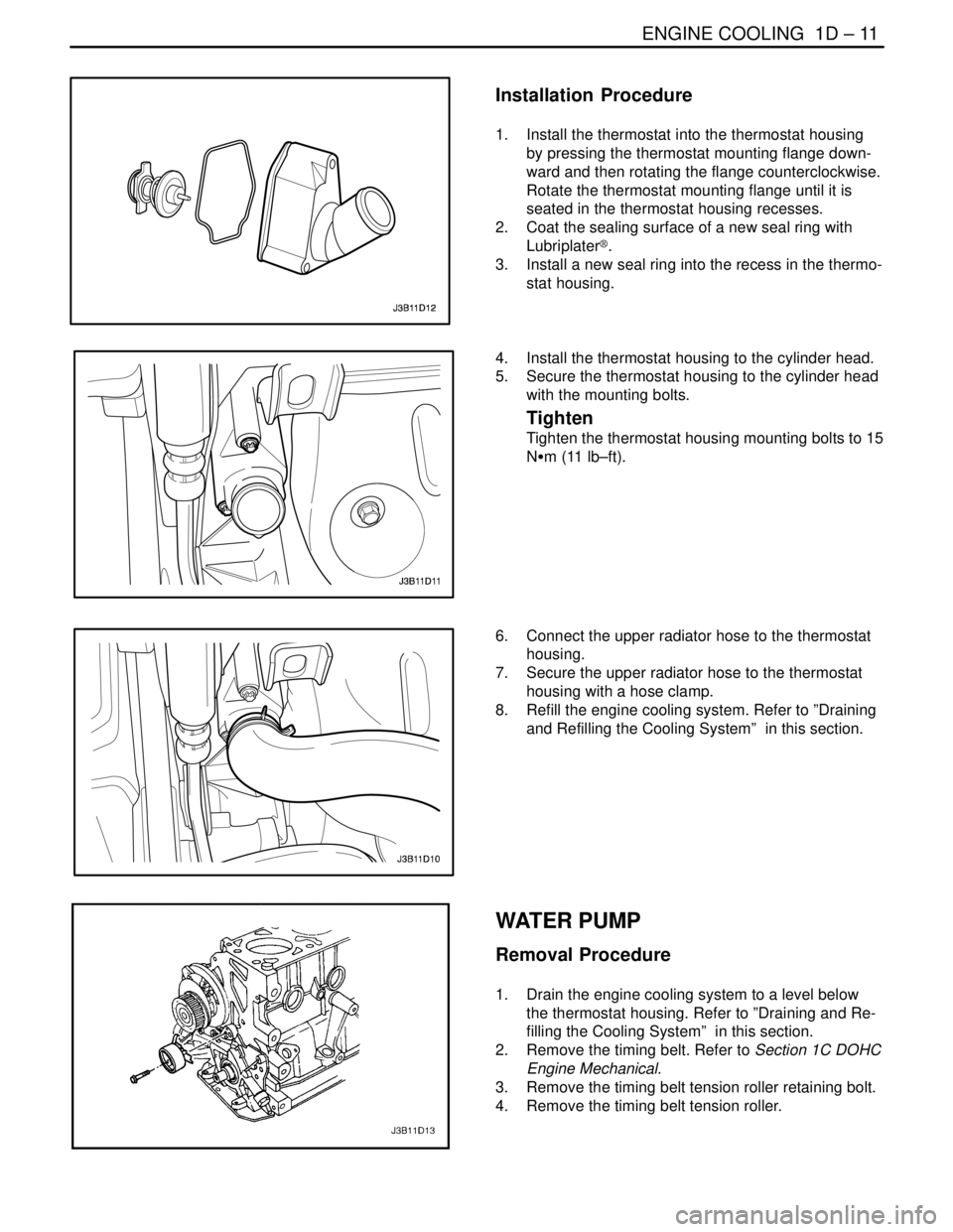
Installation Procedure
1. Install the thermostat into the thermostat housing
by pressing the thermostat mounting flange down-
ward and then rotating the flange counterclockwise.
Rotate the thermostat mounting flange until it is
seated in the thermostat housing recesses.
2. Coat the sealing surface of a new seal ring with
Lubriplater®.
3. Install a new seal ring into the recess in the thermo-
stat housing.
4. Install the thermostat housing to the cylinder head.
5. Secure the thermostat housing to the cylinder head
with the mounting bolts.
Tighten
Tighten the thermostat housing mounting bolts to 15
NSm (11 lb–ft).
6. Connect the upper radiator hose to the thermostat
housing.
7. Secure the upper radiator hose to the thermostat
housing with a hose clamp.
8. Refill the engine cooling system. Refer to ”Draining
and Refilling the Cooling System” in this section.
WATER PUMP
Removal Procedure
1. Drain the engine cooling system to a level below
the thermostat housing. Refer to ”Draining and Re-
filling the Cooling System” in this section.
2. Remove the timing belt. Refer to Section 1C DOHC
Engine Mechanical.
3. Remove the timing belt tension roller retaining bolt.
4. Remove the timing belt tension roller.
Page 207 of 2643
1D – 12IENGINE COOLING
DAEWOO V–121 BL4
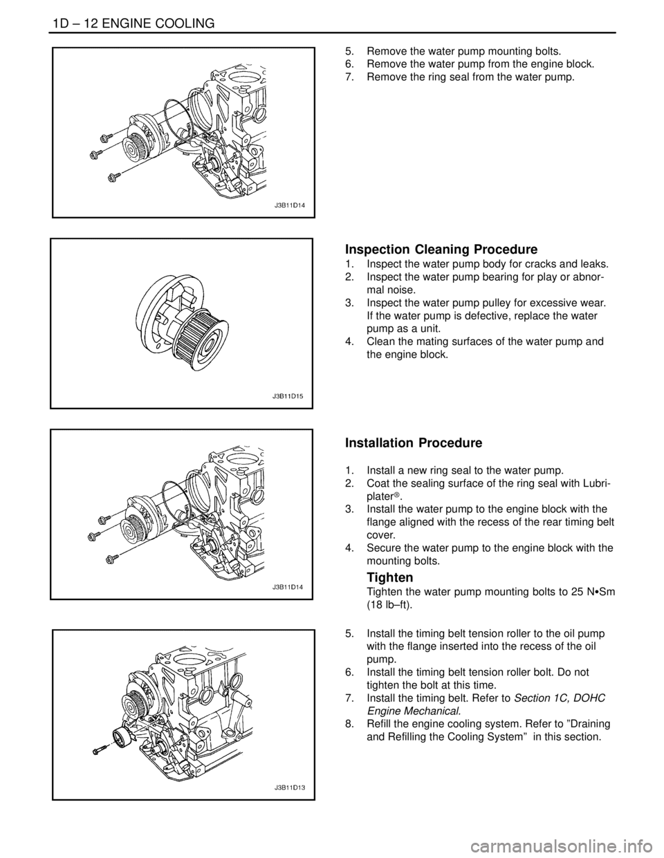
5. Remove the water pump mounting bolts.
6. Remove the water pump from the engine block.
7. Remove the ring seal from the water pump.
Inspection Cleaning Procedure
1. Inspect the water pump body for cracks and leaks.
2. Inspect the water pump bearing for play or abnor-
mal noise.
3. Inspect the water pump pulley for excessive wear.
If the water pump is defective, replace the water
pump as a unit.
4. Clean the mating surfaces of the water pump and
the engine block.
Installation Procedure
1. Install a new ring seal to the water pump.
2. Coat the sealing surface of the ring seal with Lubri-
plater®.
3. Install the water pump to the engine block with the
flange aligned with the recess of the rear timing belt
cover.
4. Secure the water pump to the engine block with the
mounting bolts.
Tighten
Tighten the water pump mounting bolts to 25 NSSm
(18 lb–ft).
5. Install the timing belt tension roller to the oil pump
with the flange inserted into the recess of the oil
pump.
6. Install the timing belt tension roller bolt. Do not
tighten the bolt at this time.
7. Install the timing belt. Refer to Section 1C, DOHC
Engine Mechanical.
8. Refill the engine cooling system. Refer to ”Draining
and Refilling the Cooling System” in this section.
Page 213 of 2643
1D – 18IENGINE COOLING
DAEWOO V–121 BL4
GENERAL DESCRIPTION
AND SYSTEM OPERATION
GENERAL DESCRIPTION
The cooling system maintains the engine temperature at
an efficient level during all engine operating conditions.
When the engine is cold, the cooling system cools the en-
gine slowly or not at all. This slow cooling of the engine al-
lows the engine to warm up quickly.
The cooling system includes a radiator and recovery sub-
system, cooling fans, a thermostat and housing, a coolant
pump, and a coolant pump drive belt. The timing belt
drives the coolant pump.
All components must function properly in order for the
cooling system to operate. The coolant pump draws the
coolant from the radiator. The coolant then circulates
through water jackets in the engine block, the intake man-
ifold, and the cylinder head. When the coolant reaches the
operating temperature of the thermostat, the thermostat
opens. The coolant then goes back to the radiator where
it cools.
This system directs some coolant through the hoses to the
heater core. This provides for heating and defrosting. The
surge tank is connected to the radiator to recover the cool-
ant displaced by expansion from the high temperatures.
The surge tank maintains the correct coolant level.
The cooling system for this vehicle has no radiator cap or
filler neck. The coolant is added to the cooling system
through the surge tank.
RADIATOR
This vehicle has a lightweight tube–and–fin aluminum ra-
diator. Plastic tanks are mounted on the right and the left
sides of the radiator core.
On vehicles equipped with automatic transaxles, the
transaxle fluid cooler lines run through the left radiator
tank. A radiator drain cock is on this radiator.
To drain the cooling system, open the drain cock.
SURGE TANK
The surge tank is a transparent plastic reservoir, similar to
the windshield washer reservoir.
The surge tank is connected to the radiator by a hose and
to the engine cooling system by another hose. As the ve-
hicle is driven, the engine coolant heats and expands. The
portion of the engine coolant displaced by this expansion
flows from the radiator and the engine into the surge tank.
The air trapped in the radiator and the engine is degassed
into the surge tank.When the engine stops, the engine coolant cools and con-
tracts. The displaced engine coolant is then drawn back
into the radiator and the engine. This keeps the radiator
filled with the coolant to the desired level at all times and
increases the cooling efficiency.
Maintain the coolant level between the MIN and the MAX
marks on the surge tank when the system is cold.
WATER PUMP
The belt–driven centrifugal water pump consists of an im-
peller, a drive shaft, and a belt pulley. The water pump is
mounted on the front of the transverse–mounted engine,
and is driven by the timing belt.
The impeller is supported by a completely sealed bearing.
The water pump is serviced as an assembly and, there-
fore, cannot be disassembled.
THERMOSTAT
A wax pellet–type thermostat controls the flow of the en-
gine coolant through the engine cooling system. The ther-
mostat is mounted in the thermostat housing to the front
of the cylinder head.
The thermostat stops the flow of the engine coolant from
the engine to the radiator in order to provide faster warm–
up, and to regulate the coolant temperature. The thermo-
stat remains closed while the engine coolant is cold, pre-
venting circulation of the engine coolant through the
radiator. At this point, the engine coolant is allowed to cir-
culate only throughout the heater core to warm it quickly
and evenly.
As the engine warms, the thermostat opens. This allows
the engine coolant to flow through the radiator, where the
heat is dissipated through the radiator. This opening and
closing of the thermostat permits enough engine coolant
to enter the radiator to keep the engine within proper en-
gine temperature operating limits.
The wax pellet in the thermostat is hermetically sealed in
a metal case. The wax element of the thermostat expands
when it is heated and contracts when it is cooled.
As the vehicle is driven and the engine warms, the engine
coolant temperature increases. When the engine coolant
reaches a specified temperature, the wax pellet element
in the thermostat expands and exerts pressure against the
metal case, forcing the valve open. This allows the engine
coolant to flow through the engine cooling system and cool
the engine.
As the wax pellet cools, the contraction allows a spring to
close the valve.
The thermostat begins to open at 87°C (189°F) and is fully
open at 102°C (216°F). The thermostat closes at 86°C
(187°F).
Page 404 of 2643
1F – 158IENGINE CONTROLS
DAEWOO V–121 BL4
DIAGNOSTIC TROUBLE CODE (DTC) P0171
FUEL TRIM SYSTEM TOO LEAN
System Description
If the adaptation value threshold is permanently exceed-
ed, the deviation of the adaptive terms enables to detect
a slow default coming out. Two time counters (one for the
rich side and another one for the lean side) are increased
while the lambda controller exceeds the adaptation
thresholds. As soon as one of the time counters reaches
its maximum value, the error is detected.
The aim of this test is to simulate a failure that would result
in exceeding the adaptive terms. Two kinds of failure must
be created.
S A lean side deviation: P0171
S A rich side deviation : P0172
It is thus necessary to determine, for each kind of failure,
the limit good and the limit bad. For a given failure, mea-
sure the emission threshold until the legal emission
thresholds are exceeded.
Note that the problem is due to the emission thresholds re-
quired, it is not simple to disturb the system so that the
emission thresholds will be exceeded. The tuning has
been made thanks to a dedicated calibration but, as such
a procedure is not permitted by the regulation, it is neces-
sary to create some material malfunction (fuel pressure
regulator, fuel injector, air leakage...).
Conditions for Setting the DTC
S DTCs P0107, P0108, P0112, P0113, P0117,
P0118, P0122, P0123, P0131, P0132, P0337,
P0338, P0341, P0342, P0400, P1319, P1402,
P1404, P1405, P1671 and P1672 are not set.
S Coolant temperature is greater than 20°C (68°F).
(1.4L DOHC)
S Coolant temperature is greater than 80°C (176°F).
(1.6L DOHC)
S Manifold Absolute Pressure (MAP) is greater than
70 kPa (10.2 psi).
S System is in closed loop.
Action Taken When the DTC Sets
S The Malfunction Indicator Lamp (MIL) will illuminate
after three consecutive trip with a fail.
S The ECM will record operating conditions at the
time the diagnostic fail. This information will be
stored in the Freeze Frame and Failure Records
buffers.S A history DTC is stored.
Conditions for Clearing the MIL/DTC
S The MIL will turn off after four consecutive ignition
cycles in which the diagnostic runs without a fault.
S A history DTC will clear after 40 consecutive warm
up cycles without a fault.
S DTC(s) can be cleared by using the scan tool.
S Disconnecting the ECM battery feed for 10 sec-
onds.
Diagnostic Aids
Important : After repairs, use the scan tool Fuel Trim Re-
set function to reset the long–term fuel trim to 128 (0%).
S Fuel pressure – The system will be lean if the pres-
sure is too low. It may be necessary to monitor fuel
pressure while driving the vehicle at various road
speeds and/or loads to confirm.
S Map sensor – An output that causes the ECM to
sense a lower than normal manifold pressure (high
vacuum) can cause the system to go lean. Discon-
necting the MAP sensor will allow the ECM to sub-
stitute a fixed (default) value for the MAP sensor. If
the lean condition is gone when the sensor is dis-
connected, substitute a known good sensor and
recheck.
S Fuel contamination – Water, in even small amounts,
near the in–tank fuel pump inlet can be delivered to
the injector. The water causes a lean exhaust and
can set DTC P0171.
Check for poor O2S or MAP sensor connection at the
ECM. Inspect the harness connectors for the following
conditions:
S Backed–out terminals
S Improper mating
S Broken locks
S Improperly formed
S Damaged terminals
S Poor terminal–to–wire connection
Inspect the wiring harness for damage. If the harness ap-
pears to be OK, observe the O2S display on the scan tool
while moving the connectors and the wiring harness re-
lated to the engine harness. A change in the display will
indicate the location of the fault.
Check the brake power booster check valve for possible
leaks.
Page 406 of 2643
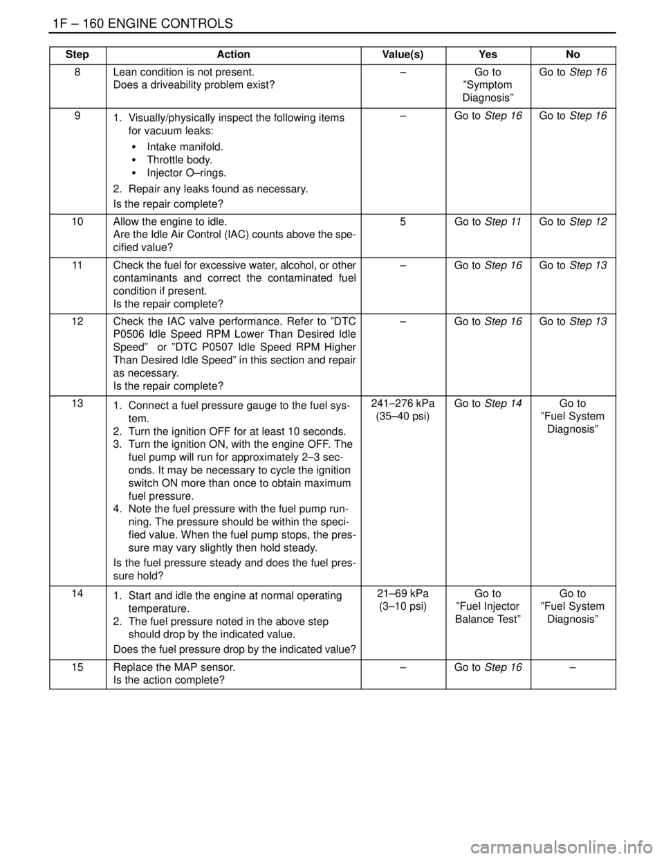
1F – 160IENGINE CONTROLS
DAEWOO V–121 BL4
StepNo Yes Value(s) Action
8Lean condition is not present.
Does a driveability problem exist?–Go to
”Symptom
Diagnosis”Go to Step 16
91. Visually/physically inspect the following items
for vacuum leaks:
S Intake manifold.
S Throttle body.
S Injector O–rings.
2. Repair any leaks found as necessary.
Is the repair complete?–Go to Step 16Go to Step 16
10Allow the engine to idle.
Are the Idle Air Control (IAC) counts above the spe-
cified value?5Go to Step 11Go to Step 12
11Check the fuel for excessive water, alcohol, or other
contaminants and correct the contaminated fuel
condition if present.
Is the repair complete?–Go to Step 16Go to Step 13
12Check the IAC valve performance. Refer to ”DTC
P0506 Idle Speed RPM Lower Than Desired Idle
Speed” or ”DTC P0507 Idle Speed RPM Higher
Than Desired Idle Speed” in this section and repair
as necessary.
Is the repair complete?–Go to Step 16Go to Step 13
131. Connect a fuel pressure gauge to the fuel sys-
tem.
2. Turn the ignition OFF for at least 10 seconds.
3. Turn the ignition ON, with the engine OFF. The
fuel pump will run for approximately 2–3 sec-
onds. It may be necessary to cycle the ignition
switch ON more than once to obtain maximum
fuel pressure.
4. Note the fuel pressure with the fuel pump run-
ning. The pressure should be within the speci-
fied value. When the fuel pump stops, the pres-
sure may vary slightly then hold steady.
Is the fuel pressure steady and does the fuel pres-
sure hold?241–276 kPa
(35–40 psi)Go to Step 14Go to
”Fuel System
Diagnosis”
141. Start and idle the engine at normal operating
temperature.
2. The fuel pressure noted in the above step
should drop by the indicated value.
Does the fuel pressure drop by the indicated value?21–69 kPa
(3–10 psi)Go to
”Fuel Injector
Balance Test”Go to
”Fuel System
Diagnosis”
15Replace the MAP sensor.
Is the action complete?–Go to Step 16–
Page 619 of 2643
ENGINE CONTROLS 1F – 373
DAEWOO V–121 BL4
Conditions for Clearing the MIL/DTC
S The MIL will turn off after four consecutive ignition
cycles in which the diagnostic runs without a fault.
S A history DTC will clear after 40 consecutive warm–
up cycles without a fault.
S The DTC(s) can be cleared by using the scan tool.
S Disconnecting the ECM battery feed for more than
10 seconds.
Diagnostic Aids
S Fuel pressure – The system will be lean if the fuel
pressure is too low. It may be necessary to monitor
the fuel pressure while driving the vehicle at various
road speeds and/or loads to confirm. Refer to ”Fuel
System Diagnosis” in this section.
S Manifold Absolute Pressure (MAP) sensor – An
output that causes the ECM to sense a lower than
normal manifold pressure (high vacuum) can cause
the system to go lean. Disconnecting the MAP sen-
sor will allow the ECM to substitute a fixed (default)
value for the MAP sensor. If the lean condition is
gone when the sensor is disconnected, substitute a
known good sensor and recheck.
S Fuel contamination – Water, in even small amounts
near the in–tank fuel pump inlet can be delivered to
the injector. The water causes a lean exhaust and
can set DTC P0131.
S Sensor harness – The HO2S1 sensor pigtail may
be mis–positioned and contacting the exhaust man-
ifold.
S Engine misfire – A misfiring cylinder will result in
unburned oxygen in the exhaust, which could cause
DTC P0131 to set. Refer to DTC P0300 Engine
Misfire in this section.S Cracked Front Heated Oxygen Sensor – A cracked
HO2S1 or poor ground at the sensor could cause
DTC P0131. Refer to”Symptoms Diagnosis” in this
section.
S Plugged fuel filter – A plugged fuel filter can cause
a lean condition and cause a DTC P0131 to set.
S Plugged Front Heated Oxygen Sensor – A plugged
reference port on the HO2S1 will indicate a lower–
than–normal voltage output from the HO2S1.
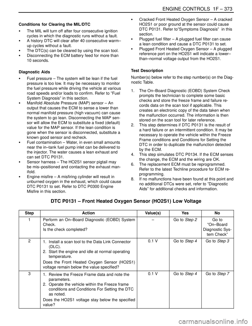
Test Description
Number(s) below refer to the step number(s) on the Diag-
nostic Table.
1. The On–Board Diagnostic (EOBD) System Check
prompts the technician to complete some basic
checks and store the freeze frame and failure re-
cords data on the scan tool if applicable. This
creates an electronic copy of the data taken when
the malfunction occurred. The information is then
stored on the scan tool for later reference.
2. This step determines if DTC P0131 is the result of
a hard failure or an intermittent condition. It may be
necessary to operate the vehicle within the Freeze
Frame conditions and Conditions for Setting the
DTC in order to duplicate the malfunction detected
by the ECM.
4. This step simulates DTC P0134. If the ECM senses
the change, the ECM and the wiring are OK.
6. The replacement ECM must be reprogrammed.
Refer to the latest Techline procedure for ECM re-
programming.
8. If no malfunctions have been found at this point and
no additional DTCs were set, refer to ”Diagnostic
Aids” for additional checks and information.
DTC P0131 – Front Heated Oxygen Sensor (HO2S1) Low Voltage
StepActionValue(s)YesNo
1Perform an On–Board Diagnostic (EOBD) System
Check.
Is the check completed?–Go to Step 2Go to
”On–Board
Diagnostic Sys-
tem Check”
21. Install a scan tool to the Data Link Connector
(DLC).
2. Start the engine and idle at normal operating
temperature.
Does the Front Heated Oxygen Sensor (HO2S1)
voltage remain below the value specified?0.1 VGo to Step 4Go to Step 3
31. Review the Freeze Frame data and note the
parameters.
2. Operate the vehicle within the Freeze frame
conditions and Conditions For Setting the DTC
as noted.
Does the HO2S1 voltage stay below the specified
value?0.1 VGo to Step 4Go to Step 7
Page 646 of 2643
1F – 400IENGINE CONTROLS
DAEWOO V–121 BL4
DIAGNOSTIC TROUBLE CODE (DTC) P0171
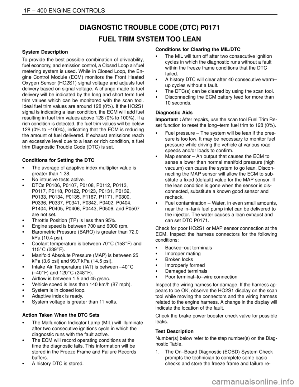
FUEL TRIM SYSTEM TOO LEAN
System Description
To provide the best possible combination of driveability,
fuel economy, and emission control, a Closed Loop air/fuel
metering system is used. While in Closed Loop, the En-
gine Control Module (ECM) monitors the Front Heated
Oxygen Sensor (HO2S1) signal voltage and adjusts fuel
delivery based on signal voltage. A change made to fuel
delivery will be indicated by the long and short term fuel
trim values which can be monitored with the scan tool.
Ideal fuel trim values are around 128 (0%). If the HO2S1
signal is indicating a lean condition, the ECM will add fuel
resulting in fuel trim values above 128 (0% to 100%). If a
rich condition is detected, the fuel trim values will be below
128 (0% to –100%), indicating that the ECM is reducing
the amount of fuel delivered. If exhaust emissions reach
an excessive level due to a lean or rich condition, a fuel
trim Diagnostic Trouble Code (DTC) is set.
Conditions for Setting the DTC
S The average of adaptive index multiplier value is
greater than 1.28.
S No intrusive tests active.
S DTCs P0106, P0107, P0108, P0112, P0113,
P0117, P0118, P0122, P0123, P0131, P0132,
P0133, P0134, P0135, P1167, P1171, P0300,
P0336, P0337, P0341, P0342, P0402, P0404,
P1404, P0405, P0406, P0443, P0506, and P0507
are not set.
S Throttle Position (TP) is less than 95%.
S Engine speed is between 700 and 6000 rpm.
S Barometric Pressure (BARO) is greater than 72.0
kPa (10.4 psi).
S Coolant temperature is between 70°C (158°F) and
11 5°C (239°F).
S Manifold Absolute Pressure (MAP) is between 25
kPa (3.6 psi) and 99.7 kPa (14.5 psi).
S Intake Air Temperature (IAT) is between –40°C
(–40°F) and 120°C (248°F).
S Airflow is between 1.5 and 45 g/sec.
S Vehicle speed is less than 140 km/h (87 mph).
S System is in closed loop.
S Adaptive index is ready.
S System voltage is greater than 11 volts.
Action Taken When the DTC Sets
S The Malfunction Indicator Lamp (MIL) will illuminate
after two consecutive ignitions cycle in which the
diagnostic runs with the fault active.
S The ECM will record operating conditions at the
time the diagnostic fails. This information will be
stored in the Freeze Frame and Failure Records
buffers.
S A history DTC is stored.Conditions for Clearing the MIL/DTC
S The MIL will turn off after two consecutive ignition
cycles in which the diagnostic runs without a fault
within the freeze frame conditions that the DTC
failed.
S A history DTC will clear after 40 consecutive warm–
up cycles without a fault.
S The DTC(s) can be cleared by using the scan tool.
S Disconnecting the ECM battery feed for more than
10 seconds.
Diagnostic Aids
Important : After repairs, use the scan tool Fuel Trim Re-
set function to reset the long–term fuel trim to 128 (0%).
S Fuel pressure – The system will be lean if the pres-
sure is too low. It may be necessary to monitor fuel
pressure while driving the vehicle at various road
speeds and/or loads to confirm.
S Map sensor – An output that causes the ECM to
sense a lower than normal manifold pressure (high
vacuum) can cause the system to go lean. Discon-
necting the MAP sensor will allow the ECM to sub-
stitute a fixed (default) value for the MAP sensor. If
the lean condition is gone when the sensor is dis-
connected, substitute a known good sensor and
recheck.
S Fuel contamination – Water, in even small amounts,
near the in–tank fuel pump inlet can be delivered to
the injector. The water causes a lean exhaust and
can set DTC P0171.
Check for poor HO2S1 or MAP sensor connection at the
ECM. Inspect the harness connectors for the following
conditions:
S Backed–out terminals
S Improper mating
S Broken locks
S Improperly formed
S Damaged terminals
S Poor terminal–to–wire connection
Inspect the wiring harness for damage. If the harness ap-
pears to be OK, observe the HO2S1 display on the scan
tool while moving the connectors and the wiring harness
related to the engine harness. A change in the display will
indicate the location of the fault.
Check the brake power booster check valve for possible
leaks.
Test Description
Number(s) below refer to the step number(s) on the Diag-
nostic Table.
1. The On–Board Diagnostic (EOBD) System Check
prompts the technician to complete some basic
checks and store the freeze frame and failure re-
Page 648 of 2643
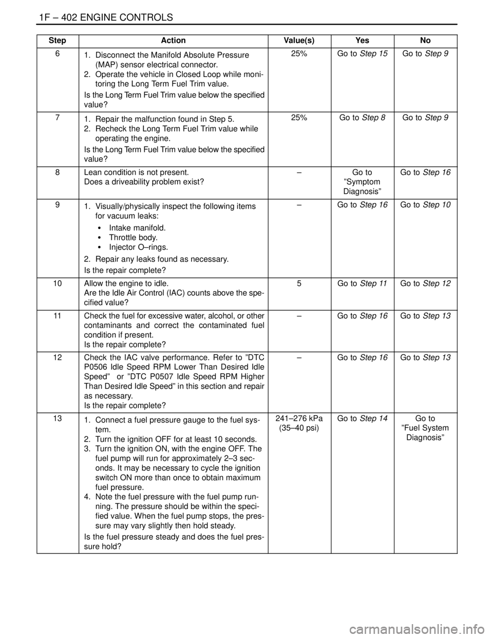
1F – 402IENGINE CONTROLS
DAEWOO V–121 BL4
StepNo Yes Value(s) Action
61. Disconnect the Manifold Absolute Pressure
(MAP) sensor electrical connector.
2. Operate the vehicle in Closed Loop while moni-
toring the Long Term Fuel Trim value.
Is the Long Term Fuel Trim value below the specified
value?25%Go to Step 15Go to Step 9
71. Repair the malfunction found in Step 5.
2. Recheck the Long Term Fuel Trim value while
operating the engine.
Is the Long Term Fuel Trim value below the specified
value?25%Go to Step 8Go to Step 9
8Lean condition is not present.
Does a driveability problem exist?–Go to
”Symptom
Diagnosis”Go to Step 16
91. Visually/physically inspect the following items
for vacuum leaks:
S Intake manifold.
S Throttle body.
S Injector O–rings.
2. Repair any leaks found as necessary.
Is the repair complete?–Go to Step 16Go to Step 10
10Allow the engine to idle.
Are the Idle Air Control (IAC) counts above the spe-
cified value?5Go to Step 11Go to Step 12
11Check the fuel for excessive water, alcohol, or other
contaminants and correct the contaminated fuel
condition if present.
Is the repair complete?–Go to Step 16Go to Step 13
12Check the IAC valve performance. Refer to ”DTC
P0506 Idle Speed RPM Lower Than Desired Idle
Speed” or ”DTC P0507 Idle Speed RPM Higher
Than Desired Idle Speed” in this section and repair
as necessary.
Is the repair complete?–Go to Step 16Go to Step 13
131. Connect a fuel pressure gauge to the fuel sys-
tem.
2. Turn the ignition OFF for at least 10 seconds.
3. Turn the ignition ON, with the engine OFF. The
fuel pump will run for approximately 2–3 sec-
onds. It may be necessary to cycle the ignition
switch ON more than once to obtain maximum
fuel pressure.
4. Note the fuel pressure with the fuel pump run-
ning. The pressure should be within the speci-
fied value. When the fuel pump stops, the pres-
sure may vary slightly then hold steady.
Is the fuel pressure steady and does the fuel pres-
sure hold?241–276 kPa
(35–40 psi)Go to Step 14Go to
”Fuel System
Diagnosis”
Page 822 of 2643
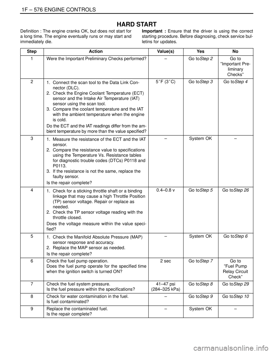
1F – 576IENGINE CONTROLS
DAEWOO V–121 BL4
HARD START
Definition : The engine cranks OK, but does not start for
a long time. The engine eventually runs or may start and
immediately die.Important : Ensure that the driver is using the correct
starting procedure. Before diagnosing, check service bul-
letins for updates.
Step
ActionValue(s)YesNo
1Were the Important Preliminary Checks performed?–Go toStep 2Go to
”Important Pre-
liminary
Checks”
21. Connect the scan tool to the Data Link Con-
nector (DLC).
2. Check the Engine Coolant Temperature (ECT)
sensor and the Intake Air Temperature (IAT)
sensor using the scan tool.
3. Compare the coolant temperature and the IAT
with the ambient temperature when the engine
is cold.
Do the ECT and the IAT readings differ from the am-
bient temperature by more than the value specified?5°F (3°C)Go toStep 3Go toStep 4
31. Measure the resistance of the ECT and the IAT
sensor.
2. Compare the resistance value to specifications
using the Temperature Vs. Resistance tables
for diagnostic trouble codes (DTCs) P0118 and
P0113.
3. If the resistance is not the same, replace the
faulty sensor.
Is the repair complete?–System OK–
41. Check for a sticking throttle shaft or a binding
linkage that may cause a high Throttle Position
(TP) sensor voltage. Repair or replace as
needed.
2. Check the TP sensor voltage reading with the
throttle closed.
Does the voltage measure within the value speci-
fied?0.4–0.8 vGo toStep 5Go toStep 26
51. Check the Manifold Absolute Pressure (MAP)
sensor response and accuracy.
2. Replace the MAP sensor as needed.
Is the repair complete?–System OKGo toStep 6
6Check the fuel pump operation.
Does the fuel pump operate for the specified time
when the ignition switch is turned ON?2 secGo toStep 7Go to
”Fuel Pump
Relay Circuit
Check”
7Check the fuel system pressure.
Is the fuel pressure within the specifications?41–47 psi
(284–325 kPa)Go toStep 8Go toStep 29
8Check for water contamination in the fuel.
Is fuel contaminated?–Go toStep 9Go toStep 10
9Replace the contaminated fuel.
Is the repair complete?–System OK–
Page 830 of 2643
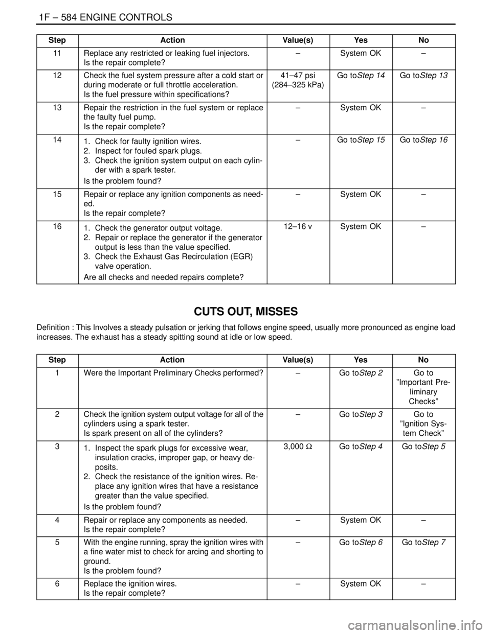
1F – 584IENGINE CONTROLS
DAEWOO V–121 BL4
StepNo Yes Value(s) Action
11Replace any restricted or leaking fuel injectors.
Is the repair complete?–System OK–
12Check the fuel system pressure after a cold start or
during moderate or full throttle acceleration.
Is the fuel pressure within specifications?41–47 psi
(284–325 kPa)Go toStep 14Go toStep 13
13Repair the restriction in the fuel system or replace
the faulty fuel pump.
Is the repair complete?–System OK–
141. Check for faulty ignition wires.
2. Inspect for fouled spark plugs.
3. Check the ignition system output on each cylin-
der with a spark tester.
Is the problem found?–Go toStep 15Go toStep 16
15Repair or replace any ignition components as need-
ed.
Is the repair complete?–System OK–
161. Check the generator output voltage.
2. Repair or replace the generator if the generator
output is less than the value specified.
3. Check the Exhaust Gas Recirculation (EGR)
valve operation.
Are all checks and needed repairs complete?12–16 vSystem OK–
CUTS OUT, MISSES
Definition : This Involves a steady pulsation or jerking that follows engine speed, usually more pronounced as engine load
increases. The exhaust has a steady spitting sound at idle or low speed.
Step
ActionValue(s)YesNo
1Were the Important Preliminary Checks performed?–Go toStep 2Go to
”Important Pre-
liminary
Checks”
2Check the ignition system output voltage for all of the
cylinders using a spark tester.
Is spark present on all of the cylinders?–Go toStep 3Go to
”Ignition Sys-
tem Check”
31. Inspect the spark plugs for excessive wear,
insulation cracks, improper gap, or heavy de-
posits.
2. Check the resistance of the ignition wires. Re-
place any ignition wires that have a resistance
greater than the value specified.
Is the problem found?3,000 ΩGo toStep 4Go toStep 5
4Repair or replace any components as needed.
Is the repair complete?–System OK–
5With the engine running, spray the ignition wires with
a fine water mist to check for arcing and shorting to
ground.
Is the problem found?–Go toStep 6Go toStep 7
6Replace the ignition wires.
Is the repair complete?–System OK–