light DAEWOO LACETTI 2004 Service Repair Manual
[x] Cancel search | Manufacturer: DAEWOO, Model Year: 2004, Model line: LACETTI, Model: DAEWOO LACETTI 2004Pages: 2643, PDF Size: 80.54 MB
Page 2329 of 2643

9E – 30IINSTRUMENTATION/DRIVER INFORMATION
DAEWOO V–121 BL4
GENERAL DESCRIPTION
AND SYSTEM OPERATION
CIGAR LIGHTER
The cigar lighter is located in the front portion of the floor
console. To use the lighter, push it in completely. When the
lighter is hot, it will release itself from contact with the heat-
ing element. The lighter and the heating element can be
damaged if the lighter is not allowed to release itself fully
from the heating element.
ASHTRAY
The ashtray is located below the audio system. To access
the ashtray, pull it out from the center console. The ashtray
lamp will go on when the parking lamps or the headlamps
are turned on.
INSTRUMENT PANEL VENTS
The center and the side vents in the instrument panel can
be adjusted up and down and from side to side. The side
vents can also be aimed toward the side windows in order
to defog them.
GLOVE BOX
The glove box can be opened by pulling up on the latch
handle. The glove box must be removed in order to gain
access to the passenger’s side airbag module.
DIGTAL CLOCK
The digital clock is located in the instrument panel, above
the audio system. The clock is capable of a 12–hour or a
24–hour display.
INSTRUMENT CLUSTER
The instrument cluster is located above the steering col-
umn and in the instrument cluster trim panel. The instru-
ment cluster contains the instruments that provide the
driver with vehicle performance information. The instru-
ment cluster contains a speedometer, an odometer, a trip
odometer, a temperature gauge, a fuel gauge, and several
indicator lamps. For replacement of the indicator lamp
bulbs contained in the instrument cluster, refer to ”Instru-
ment Cluster Indicator Lamps Specifications” and”Instru-
ment Cluster Indicator Lamps” in this section.
SPEEDOMETER/ODOMETER/TRIP
ODOMETER
The speedometer measures the speed of the vehicle in
km/h (mph in some countries). It consists of an instrument
cluster gauge connected to the vehicle speed sensor
(VSS) on the transaxle output shaft.The odometer measures in kilometers (miles in some
countries) the total distance the vehicle has traveled since
it was manufactured. It consists of an instrument cluster
gauge connected to the VSS on the transaxle output shaft.
The trip odometer measures the distance the vehicle has
traveled since the odometer was last reset. It consists of
an instrument cluster gauge connected to the VSS on the
transaxle output shaft. The trip odometer can be reset to
zero at any time so that the driver can record the distance
traveled from any starting point.
FUEL GAUGE
The fuel gauge consists of an instrument cluster gauge
connected to a sending unit in the fuel tank.
The fuel gauge indicates the quantity of fuel in the tank
only when the ignition switch is turned to ON or ACC.
When the ignition is turned to LOCK or START, the pointer
may come to rest at any position.
TEMPERATURE GAUGE
The temperature gauge consists of an instrument cluster
gauge connected to a temperature sensor that is in con-
tact with the circulating engine coolant.
The temperature gauge indicates the temperature of the
coolant. Prolonged driving or idling in very hot weather
may cause the pointer to move beyond the center of the
gauge. The engine is overheating if the pointer moves into
the red zone at the upper limit of the gauge.
INSTRUMENT CLUSTER INDICATOR
LAMPS
The instrument cluster contains indicator lamps that indi-
cate the functioning of certain systems or the existence of
potential problems with the operation of the vehicle. The
indicator lamps are replaceable. For replacement of the in-
dicator lamps contained in the instrument cluster, refer to
”Instrument Cluster Indicator Lamps Specifications”
and”Instrument Cluster Indicator Lamps” in this section.
CHIME MODULE
The chime module is located above the instrument panel
fuse block and will sound in order to bring attention to one
or more of the following conditions:
S The lamps are on, the door is ajar, and the ignition
switch is not in ACC, ON, or START.
S The seat belt is unbuckled when the ignition switch
is in ON or START.
S The door is open when the ignition switch is in ON
or START.
S The key is left in the ignition switch when the igni-
tion is in LOCK and the door is open.
Page 2340 of 2643

AUDIO SYSTEMS 9F – 11
DAEWOO V–121 BL4
GENERAL DESCRIPTION
AND SYSTEM OPERATION
STEREO CASSETTE AM/FM RADIO
There are three audio systems offered. The stereo digital
logic cassette AM/FM radio with electronic tape ejection
is offered in standard and deluxe models. Both models
feature RDS (radio data system) which automatically se-
lects the best station within the chain of RDS stations cur-
rently being listened to. A trunk mounted CD changer is
also available.
AUDIO SCURITY SYSTEM
The audio security system is activated whenever the audio
system circuit is disconnected from the battery. A four–
digit security code must be entered in order for the audio
system to resume functioning. The security code is
stamped on a card located in the vehicle (usually in the
glove box). The following security code entering proce-
dure must be used to deactivate the audio security sys-
tem:
1. After connecting the audio security system to the
battery, ”CODE” will flash on the display.
2. Enter the proper security number into the unit, us-
ing the preset buttons No. 1 through 8.
3. For example, if the security number is ”1234”:
a. Press the preset button No. 1. ”CODE” will
disappear and ”1 – – – ” will appear on the dis-
play.
b. Press the preset button No. 2, and ”12 – – ”
will appear.
c. Press the preset button No. 3, and ”123– ” will
appear.
d. Press the preset button No. 4, and ”1234” will
appear and flash three times.4. The audio system will function and will transfer to
the radio.
If the incorrect security number is entered into the unit,
”Err” will appear followed by ”CODE” and there will be sev-
eral audible beeps. If this happens, repeat the security en-
tering procedure beginning with Step 2.
SPEAKERS
All audio systems use eight speakers, four speakers and
four tweeters mounted in each door.
TAPE PLAYER AND CASSETTE
CARE
The head and the capstan are the two parts of the tape
player that should be cleaned. This service should be per-
formed every 100 hours of cassette operation.
To clean the head and the capstan, use a cotton swab
dipped in rubbing alcohol.
A cassette cleaning kit may also be used to clean the head
and the capstan. Follow the cleaning kit instructions to
clean the tape player.
Do not touch the tape head with magnetized tools. If the
head becomes magnetized, it will degrade cassettes
played in the player. No service is performed on the cas-
settes. The cassette manufacturer handles warranties of
the cassettes. Store cassettes away from extreme heat
and direct sunlight.
COMPACT DISC CARE
Handle discs carefully. Store the discs in protective cases
away from the sun, heat, and dust. If the surface is soiled,
dampen a clean, soft cloth in a solution of mild neutral de-
tergent and wipe the disc clean.
Page 2350 of 2643

9G – 10IINTERIOR TRIM
DAEWOO V–121 BL4
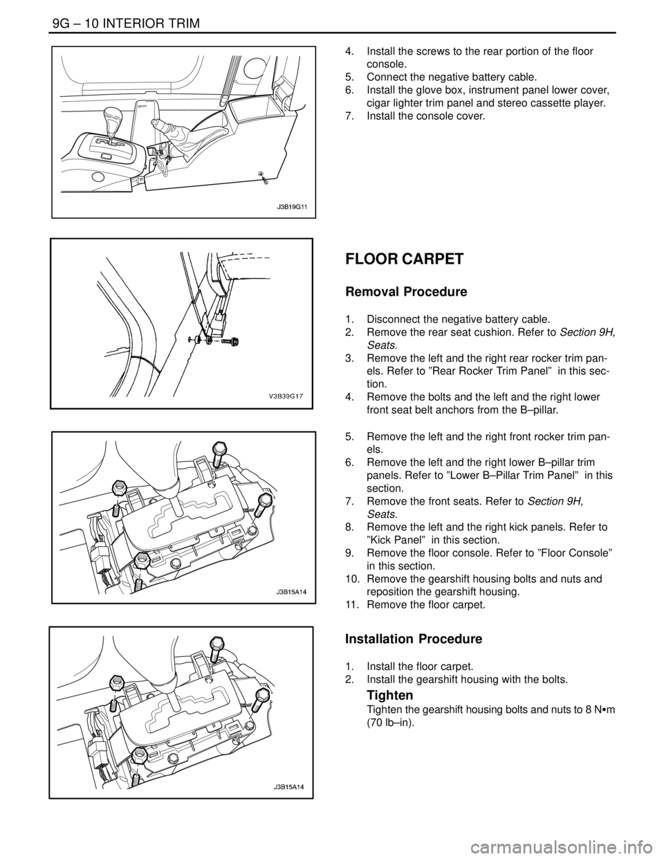
4. Install the screws to the rear portion of the floor
console.
5. Connect the negative battery cable.
6. Install the glove box, instrument panel lower cover,
cigar lighter trim panel and stereo cassette player.
7. Install the console cover.
FLOOR CARPET
Removal Procedure
1. Disconnect the negative battery cable.
2. Remove the rear seat cushion. Refer to Section 9H,
Seats.
3. Remove the left and the right rear rocker trim pan-
els. Refer to ”Rear Rocker Trim Panel” in this sec-
tion.
4. Remove the bolts and the left and the right lower
front seat belt anchors from the B–pillar.
5. Remove the left and the right front rocker trim pan-
els.
6. Remove the left and the right lower B–pillar trim
panels. Refer to ”Lower B–Pillar Trim Panel” in this
section.
7. Remove the front seats. Refer to Section 9H,
Seats.
8. Remove the left and the right kick panels. Refer to
”Kick Panel” in this section.
9. Remove the floor console. Refer to ”Floor Console”
in this section.
10. Remove the gearshift housing bolts and nuts and
reposition the gearshift housing.
11. Remove the floor carpet.
Installation Procedure
1. Install the floor carpet.
2. Install the gearshift housing with the bolts.
Tighten
Tighten the gearshift housing bolts and nuts to 8 NSm
(70 lb–in).
Page 2356 of 2643

9G – 16IINTERIOR TRIM
DAEWOO V–121 BL4
GENERAL DESCRIPTION
AND SYSTEM OPERATION
INTERIOR TRIM PANELS
The interior trim panels are molded plastic and fasten with
screws or plastic clips.
PRESSURE RELIEF VENT
When all the windows are closed and the ventilation sys-
tem is on, the addition of outside air to the interior of the
vehicle causes a positive pressure within the vehicle. To
relieve the pressure, air is released through a pressure re-
lief vent. The pressure relief vents are located at the rear
quarter of the vehicle, behind the bumper fascia.
FLOOR CONSOLE
The floor console fits over the tunnel in the floor of the ve-
hicle and extends from under the center of the instrument
panel to the rear seat area. The front portion of the consolecontains the cigar lighter and the transaxle shift lever. The
rear portion of the console contains the parking brake le-
ver, a cupholder, a storage compartment, and an ashtray
for the rear seat occupants.
The sensing and diagnostic module (SDM) for the airbag
system and the remote keyless entry module are located
under the console.
FLOOR CARPET
The one–piece floor carpet goes over both the front and
the rear floor pans.
REAR COMPARTMENT SECURITY
COVER (HATCHBACK)
A rear compartment security cover is provided on the
hatchback model. The security cover is attached to the
hatch and can be easily removed if more cargo space is
needed.
Page 2377 of 2643

SECTION : 9K
SQUEAKS AND RATTLES
TABLE OF CONTENTS
DIAGNOSIS9K–1 . . . . . . . . . . . . . . . . . . . . . . . . . . . . . . . .
Squeak and Rattle Diagnosis 9K–1. . . . . . . . . . . . . . . .
MAINTENANCE AND REPAIR9K–3 . . . . . . . . . . . . . . . ON–VEHICLE SERVICE 9K–3. . . . . . . . . . . . . . . . . . . . .
Squeak and Rattle Repair 9K–3. . . . . . . . . . . . . . . . . . .
DIAGNOSIS
SQUEAK AND RATTLE DIAGNOSIS
Rattle Coming From the Side Rail
ChecksAction
Check the brake lines.S Tap lightly on the brake lines and listen for a rattle.
S Install plastic tie straps to secure the brake lines
tightly together.
Rattle Under Vehicle at Higher RPM
ChecksAction
Check for heat shield contact with the underbody.S Raise the vehicle and perform a visual inspection.
S Bend the heat shield slightly to gain clearance from
the underbody.
Squeak From the Front of the Vehicle in Cold Weather
ChecksAction
Check the front stabilizer shaft insulators.S While the vehicle is cold, perform a test drive and
achieve full front suspension travel by driving through
a dip in the road.
S Remove the insulators and wrap teflon tape around
the stabilizer shaft. Reinstall the insulators over the
tape.
Thump From Rear of Vehicle on Bumps
ChecksAction
Check for a properly secured spare tire in the rear
compartment.S Open the rear compartment and perform a visual
inspection of the spare tire and the tools.
S Tightly secure the spare tire and all tools.
S Perform a road test to verify that the noise is elimi-
nated.
Page 2378 of 2643

9K – 2ISQUEAKS AND RATTLES
DAEWOO V–121 BL4
Glass Knock Coming From the Rear of the Vehicle When Driving
Over Bumps
ChecksAction
Check for an out–of–adjustment hatchback latch.S Test drive the vehicle in order to verify this condition.
S Loosen the latch nuts and adjust the latch downward.
Rattle Coming From Door
Checks Action
Check the door lock solenoid.S Remove the door trim panel and check if the sole-
noid is loose.
S Tighten the solenoid bolts.
Check for rattling electrical connectors inside the door trim
panel.S Tap on the trim panel and listen for a rattle.
S Remove the trim panel and wrap foam padding
around the connectors as required.
Squeak When Operating Doors
ChecksAction
Check for a lack of lubrication of the door hinge pins.S Operate the doors and listen for squeaks.
S Lubricate the door hinge pins with light oil and coat
with lithium grease.
Squeak Coming From Console When Shifting Manual Transaxle
(Condition Occurs In Cold Weather with a Cold Engine)
Checks Action
Check the manual transaxle control lever lower boot.S Move the control lever between gears and listen for
squeaks.
S Remove the floor console and replace the lower shift
boot or apply talcum powder to the lower shift boot.
Buzz From the Left Side of Instrument Panel
ChecksAction
Check for vibration of the fuse box cover against the instru-
ment panel side trim.S Tap on the cover with a finger and listen for a buzz.
S Apply 6.35 mm (0.250 inch) by 25.4 mm (1.00 inch)
felt pads to the side trim where the cover makes con-
tact.
Squeak Coming From Instrument Cluster Trim Plate
Checks Action
Check for rubbing of the cluster trim plate on the instru-
ment panel.S Test drive the vehicle in order to verify this condition.
S Remove the instrument cluster trim plate and install
felt tape to the edges.
Page 2384 of 2643

GLASS AND MIRRORS 9L – 5
DAEWOO V–121 BL4
DIAGNOSIS
TESTING REAR WINDOW
DEFOGGER GRID LINE
If it has been observed during use that a grid line is inop-
erative, the following procedure can be used to find the
break. If none of the grid lines is operating, a full system
diagnosis should be completed before attempting to repair
the grid lines.
1. Turn the ignition ON.
2. Turn the rear window defogger on.
3. From the inside of the vehicle, connect a voltmeter
to each end of a grid line. The voltmeter will indi-
cate battery voltage if the grid line is open.
Notice : Use care when touching the voltmeter leads to a
grid line. If the leads are roughly applied, the grid line may
be scratched, resulting in an open circuit.4. If a grid line is found to be open, move a voltmeter
lead from one side of the grid line and retest at a
point nearer to the other side of the window. Contin-
ue to retest, each time bringing one of the voltmeter
leads closer to the opposite side of the window
from where it was originally placed. The break in
the grid line is at the point where the voltmeter be-
gins reading 0 volts instead of battery voltage.
5. Use a marking crayon to lightly mark the break
point on the rear window. Mark the glass instead of
marking directly on the grid line, and make the
mark far enough from the grid line so that it can
easily be removed without disturbing the repair.
6. Use a grid line repair kit to fix the break in the grid
line. Refer to ”Rear Window Defogger Grid Line
Repair” in this section.
OUTSIDE REARVIEW MIRROR DEFOGGERS
StepActionValue(s)YesNo
1Check the rear window defogger.
Does the rear window defogger work?–Go to Step 4 Go to Step 2
2Repair the rear window defogger before proceeding
with the outside rearview mirror diagnosis.
Is the repair complete?–Go to Step 3–
3Test the outside rearview mirror defoggers.
Does the repair of the rear window defogger system
also fix the problem with the outside rearview mirror
defoggers?–System OKGo to Step 4
4Check fuse Ef25.
Is fuse Ef25 blown?–Go to Step 5 Go to Step 6
51. Check for a short circuit and repair it, if neces-
sary.
2. Replace the fuse.
Is the repair complete?–System OK–
61. On the side of the vehicle which has the mal-
functioning outside rearview mirror defogger,
remove the black plastic escutcheon from the
trim panel side of the door.
2. Disconnect the outside rearview mirror electri-
cal connector.
3. Turn the ignition ON.
4. Turn on the defogger.
5. Use a voltmeter to backprobe terminal 3 (ORN)
at the outside rearview mirror electrical connec-
tor.
Does the voltmeter indicate the specified value?11–14 v Go to Step 8 Go to Step 7
7Repair the open circuit between fuse Ef25 and the
outside rearview mirror connector.
Is the repair complete?–System OK–
Page 2413 of 2643

9O – 2IBUMPERS AND FASCIAS
DAEWOO V–121 BL4
MAINTENANCE AND REPAIR
ON–VEHICLE SERVICE
FRONT BUMPER FASCIA
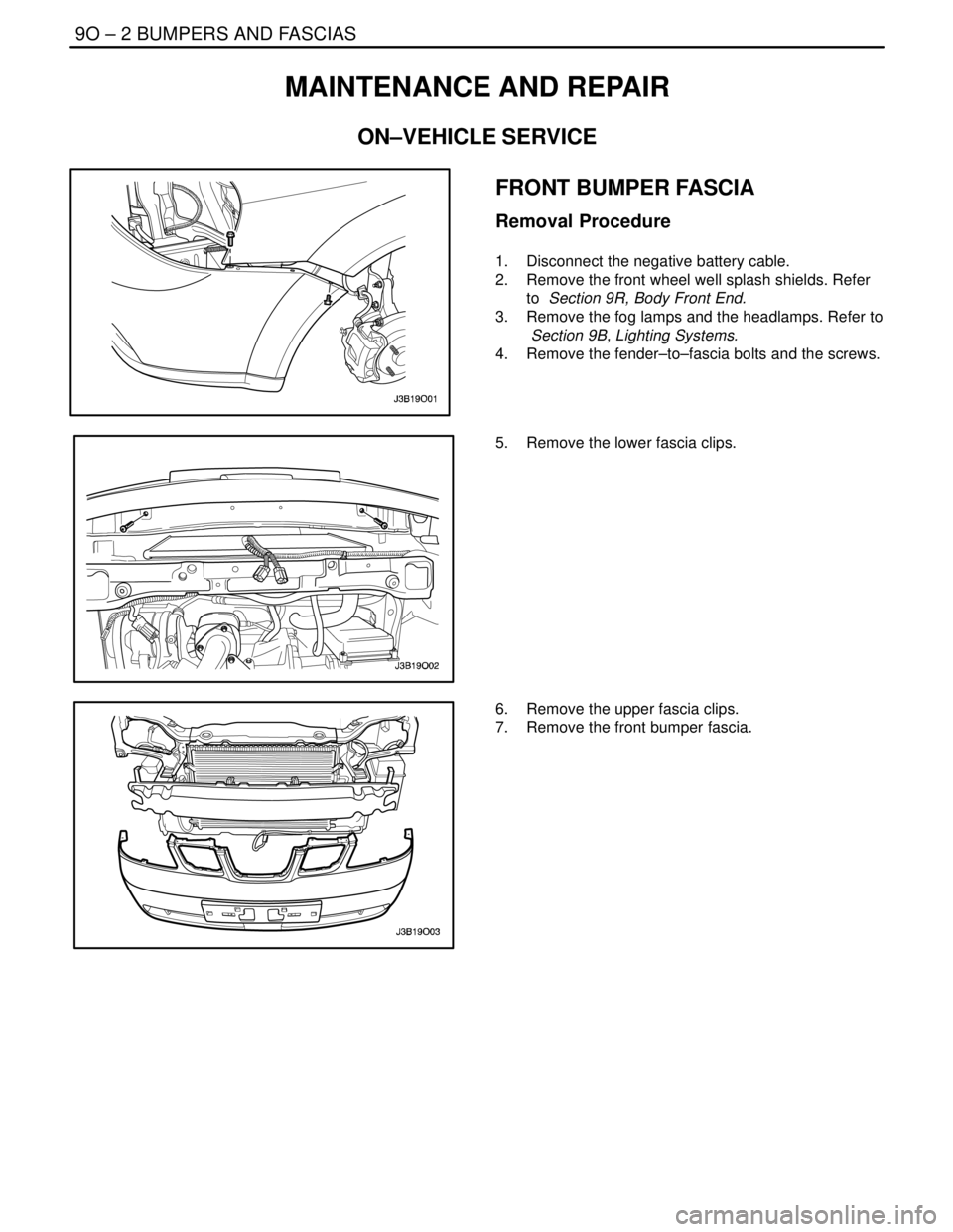
Removal Procedure
1. Disconnect the negative battery cable.
2. Remove the front wheel well splash shields. Refer
to Section 9R, Body Front End.
3. Remove the fog lamps and the headlamps. Refer to
Section 9B, Lighting Systems.
4. Remove the fender–to–fascia bolts and the screws.
5. Remove the lower fascia clips.
6. Remove the upper fascia clips.
7. Remove the front bumper fascia.
Page 2414 of 2643

BUMPERS AND FASCIAS 9O – 3
DAEWOO V–121 BL4
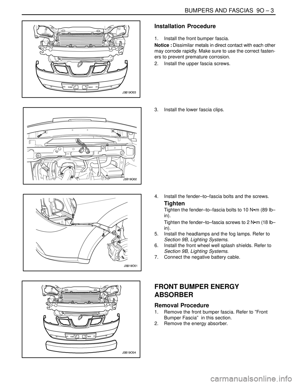
Installation Procedure
1. Install the front bumper fascia.
Notice : Dissimilar metals in direct contact with each other
may corrode rapidly. Make sure to use the correct fasten-
ers to prevent premature corrosion.
2. Install the upper fascia screws.
3. Install the lower fascia clips.
4. Install the fender–to–fascia bolts and the screws.
Tighten
Tighten the fender–to–fascia bolts to 10 NSm (89 lb–
in).
Tighten the fender–to–fascia screws to 2 NSm (18 lb–
in).
5. Install the headlamps and the fog lamps. Refer to
Section 9B, Lighting Systems.
6. Install the front wheel well splash shields. Refer to
Section 9B, Lighting Systems.
7. Connect the negative battery cable.
FRONT BUMPER ENERGY
ABSORBER
Removal Procedure
1. Remove the front bumper fascia. Refer to ”Front
Bumper Fascia” in this section.
2. Remove the energy absorber.
Page 2442 of 2643

9P – 22IDOORS
DAEWOO V–121 BL4
DOOR LOCK STRIKER ADJUSTMENT
(Front Door Shown, Rear Door Similar)
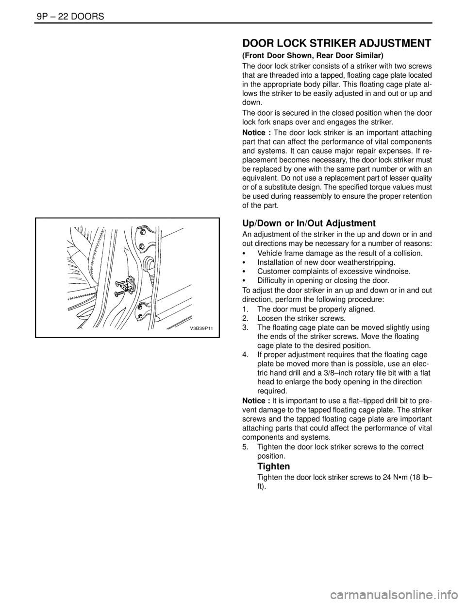
The door lock striker consists of a striker with two screws
that are threaded into a tapped, floating cage plate located
in the appropriate body pillar. This floating cage plate al-
lows the striker to be easily adjusted in and out or up and
down.
The door is secured in the closed position when the door
lock fork snaps over and engages the striker.
Notice : The door lock striker is an important attaching
part that can affect the performance of vital components
and systems. It can cause major repair expenses. If re-
placement becomes necessary, the door lock striker must
be replaced by one with the same part number or with an
equivalent. Do not use a replacement part of lesser quality
or of a substitute design. The specified torque values must
be used during reassembly to ensure the proper retention
of the part.
Up/Down or In/Out Adjustment
An adjustment of the striker in the up and down or in and
out directions may be necessary for a number of reasons:
S Vehicle frame damage as the result of a collision.
S Installation of new door weatherstripping.
S Customer complaints of excessive windnoise.
S Difficulty in opening or closing the door.
To adjust the door striker in an up and down or in and out
direction, perform the following procedure:
1. The door must be properly aligned.
2. Loosen the striker screws.
3. The floating cage plate can be moved slightly using
the ends of the striker screws. Move the floating
cage plate to the desired position.
4. If proper adjustment requires that the floating cage
plate be moved more than is possible, use an elec-
tric hand drill and a 3/8–inch rotary file bit with a flat
head to enlarge the body opening in the direction
required.
Notice : It is important to use a flat–tipped drill bit to pre-
vent damage to the tapped floating cage plate. The striker
screws and the tapped floating cage plate are important
attaching parts that could affect the performance of vital
components and systems.
5. Tighten the door lock striker screws to the correct
position.
Tighten
Tighten the door lock striker screws to 24 NSm (18 lb–
ft).