door lock DAEWOO LACETTI 2004 Service Owner's Guide
[x] Cancel search | Manufacturer: DAEWOO, Model Year: 2004, Model line: LACETTI, Model: DAEWOO LACETTI 2004Pages: 2643, PDF Size: 80.54 MB
Page 2056 of 2643
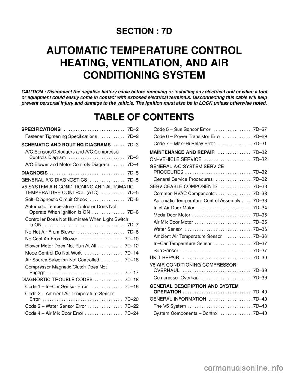
SECTION : 7D
AUTOMATIC TEMPERATURE CONTROL
HEATING, VENTILATION, AND AIR
CONDITIONING SYSTEM
CAUTION : Disconnect the negative battery cable before removing or installing any electrical unit or when a tool
or equipment could easily come in contact with exposed electrical terminals. Disconnecting this cable will help
prevent personal injury and damage to the vehicle. The ignition must also be in LOCK unless otherwise noted.
TABLE OF CONTENTS
SPECIFICATIONS7D–2 . . . . . . . . . . . . . . . . . . . . . . . . . .
Fastener Tightening Specifications 7D–2. . . . . . . . . . .
SCHEMATIC AND ROUTING DIAGRAMS7D–3 . . . . .
A/C Sensors/Defoggers and A/C Compressor
Controls Diagram 7D–3. . . . . . . . . . . . . . . . . . . . . . . .
A/C Blower and Motor Controls Diagram 7D–4. . . . . .
DIAGNOSIS7D–5 . . . . . . . . . . . . . . . . . . . . . . . . . . . . . . . .
GENERAL A/C DIAGNOSTICS 7D–5. . . . . . . . . . . . . . .
V5 SYSTEM AIR CONDITIONING AND AUTOMATIC
TEMPERATURE CONTROL (ATC) 7D–5. . . . . . . . . .
Self–Diagnostic Circuit Check 7D–5. . . . . . . . . . . . . . .
Automatic Temperature Controller Does Not
Operate When Ignition Is ON 7D–6. . . . . . . . . . . . . .
Controller Does Not Illuminate When Light Switch
Is ON 7D–7. . . . . . . . . . . . . . . . . . . . . . . . . . . . . . . . . .
No Hot Air From Blower 7D–8. . . . . . . . . . . . . . . . . . . .
No Cool Air From Blower 7D–10. . . . . . . . . . . . . . . . . .
Blower Motor Does Not Run At All 7D–12. . . . . . . . . .
Mode Control Do Not Work 7D–14. . . . . . . . . . . . . . . .
Air Source Selection Not Controlled 7D–16. . . . . . . . .
Compressor Magnetic Clutch Does Not
Engage 7D–17. . . . . . . . . . . . . . . . . . . . . . . . . . . . . . . .
DIAGNOSTIC TROUBLE CODES 7D–18. . . . . . . . . . . .
Code 1 – In–Car Sensor Error 7D–18. . . . . . . . . . . . .
Code 2 – Ambient Air Temperature Sensor
Error 7D–20. . . . . . . . . . . . . . . . . . . . . . . . . . . . . . . . . .
Code 3 – Water Sensor Error 7D–22. . . . . . . . . . . . . . .
Code 4 – Air Mix Door Error 7D–24. . . . . . . . . . . . . . . . Code 5 – Sun Sensor Error 7D–27. . . . . . . . . . . . . . . .
Code 6 – Power Transistor Error 7D–29. . . . . . . . . . . .
Code 7 – Max–Hi Relay Error 7D–31. . . . . . . . . . . . . .
MAINTENANCE AND REPAIR7D–32 . . . . . . . . . . . . . .
ON–VEHICLE SERVICE 7D–32. . . . . . . . . . . . . . . . . . . .
GENERAL A/C SYSTEM SERVICE
PROCEURES 7D–32. . . . . . . . . . . . . . . . . . . . . . . . . . . .
General Service Procedures 7D–32. . . . . . . . . . . . . . .
SERVICEABLE COMPONENTS 7D–33. . . . . . . . . . . . .
Common HVAC Components 7D–33. . . . . . . . . . . . . . .
Automatic Temperature Control Assembly 7D–33. . . .
Inlet Air Door Motor 7D–34. . . . . . . . . . . . . . . . . . . . . . .
Mode Door Motor 7D–35. . . . . . . . . . . . . . . . . . . . . . . . .
Air Mix Door Motor 7D–35. . . . . . . . . . . . . . . . . . . . . . . .
Water Sensor 7D–36. . . . . . . . . . . . . . . . . . . . . . . . . . . .
Ambient Air Temperature Sensor 7D–36. . . . . . . . . . .
In–Car Temperature Sensor 7D–37. . . . . . . . . . . . . . . .
Sun Sensor 7D–37. . . . . . . . . . . . . . . . . . . . . . . . . . . . . .
UNIT REPAIR 7D–39. . . . . . . . . . . . . . . . . . . . . . . . . . . . .
V5 AIR CONDITIONING COMPRESSOR
OVERHAUL 7D–39. . . . . . . . . . . . . . . . . . . . . . . . . . . . .
Compressor Overhaul 7D–39. . . . . . . . . . . . . . . . . . . . .
GENERAL DESCRIPTION AND SYSTEM
OPERATION7D–40 . . . . . . . . . . . . . . . . . . . . . . . . . . . . .
GENERAL INFORMATION 7D–40. . . . . . . . . . . . . . . . . .
The V5 System 7D–40. . . . . . . . . . . . . . . . . . . . . . . . . . .
System Components – Control 7D–40. . . . . . . . . . . . .
Page 2207 of 2643
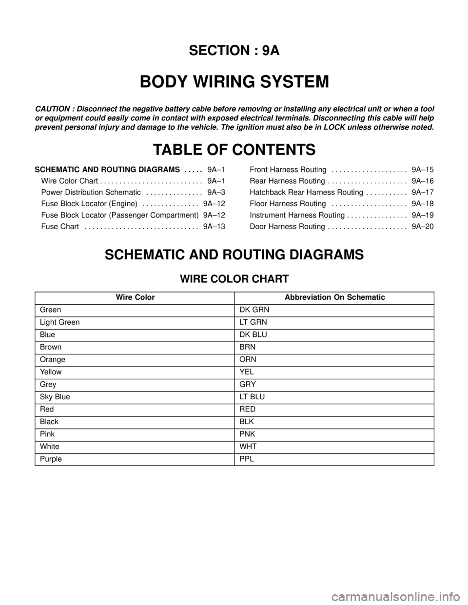
SECTION : 9A
BODY WIRING SYSTEM
CAUTION : Disconnect the negative battery cable before removing or installing any electrical unit or when a tool
or equipment could easily come in contact with exposed electrical terminals. Disconnecting this cable will help
prevent personal injury and damage to the vehicle. The ignition must also be in LOCK unless otherwise noted.
TABLE OF CONTENTS
SCHEMATIC AND ROUTING DIAGRAMS9A–1 . . . . .
Wire Color Chart 9A–1. . . . . . . . . . . . . . . . . . . . . . . . . . .
Power Distribution Schematic 9A–3. . . . . . . . . . . . . . .
Fuse Block Locator (Engine) 9A–12. . . . . . . . . . . . . . .
Fuse Block Locator (Passenger Compartment) 9A–12
Fuse Chart 9A–13. . . . . . . . . . . . . . . . . . . . . . . . . . . . . . Front Harness Routing 9A–15. . . . . . . . . . . . . . . . . . . .
Rear Harness Routing 9A–16. . . . . . . . . . . . . . . . . . . . .
Hatchback Rear Harness Routing 9A–17. . . . . . . . . . .
Floor Harness Routing 9A–18. . . . . . . . . . . . . . . . . . . .
Instrument Harness Routing 9A–19. . . . . . . . . . . . . . . .
Door Harness Routing 9A–20. . . . . . . . . . . . . . . . . . . . .
SCHEMATIC AND ROUTING DIAGRAMS
WIRE COLOR CHART
Wire ColorAbbreviation On Schematic
GreenDK GRN
Light GreenLT GRN
BlueDK BLU
BrownBRN
OrangeORN
YellowYEL
GreyGRY
Sky BlueLT BLU
RedRED
BlackBLK
PinkPNK
WhiteWHT
PurplePPL
Page 2219 of 2643
BODY WIRING SYSTEM 9A – 13
DAEWOO V–121 BL4
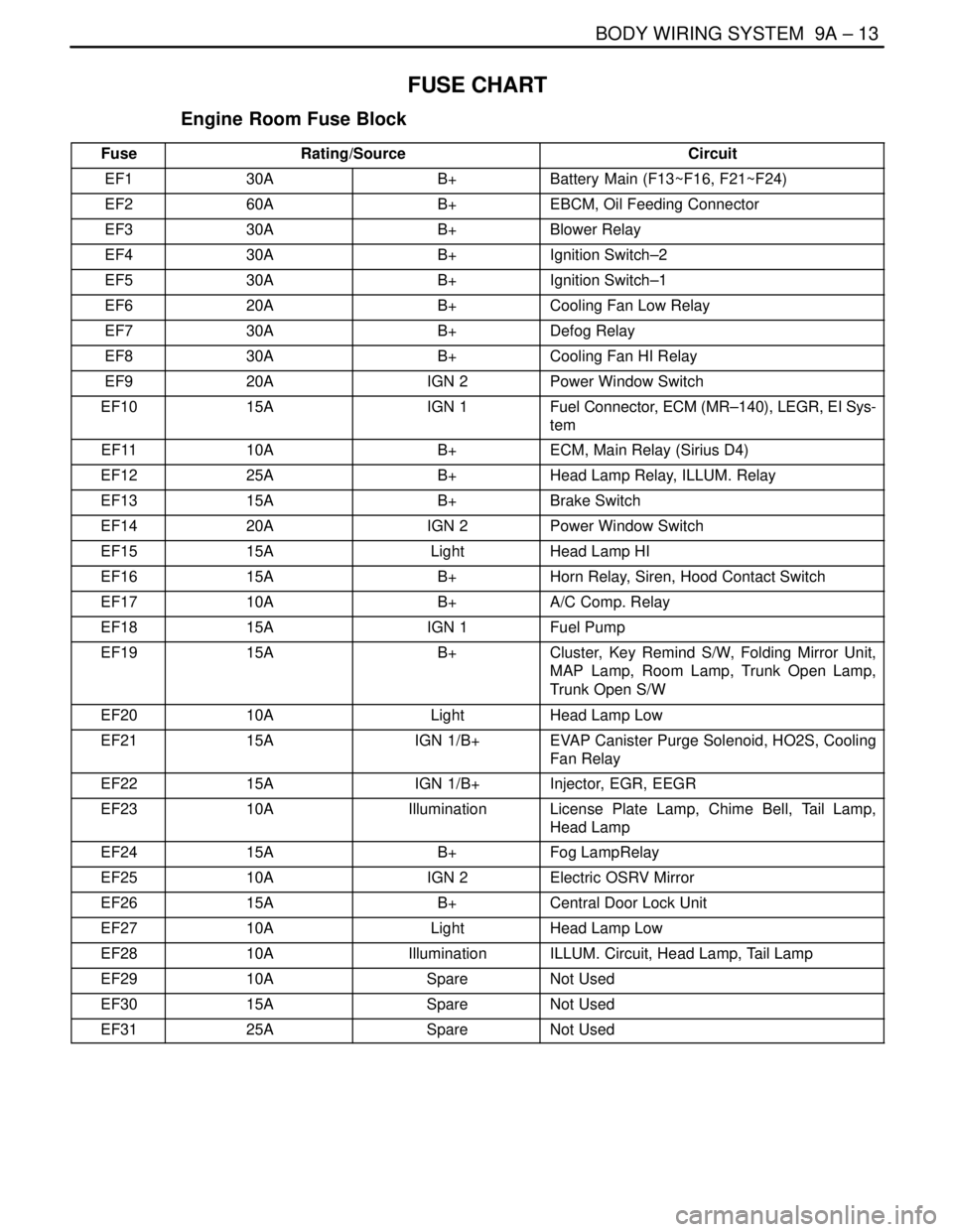
FUSE CHART
Engine Room Fuse Block
FuseRating/SourceCircuit
EF130AB+Battery Main (F13~F16, F21~F24)
EF260AB+EBCM, Oil Feeding Connector
EF330AB+Blower Relay
EF430AB+Ignition Switch–2
EF530AB+Ignition Switch–1
EF620AB+Cooling Fan Low Relay
EF730AB+Defog Relay
EF830AB+Cooling Fan HI Relay
EF920AIGN 2Power Window Switch
EF1015AIGN 1Fuel Connector, ECM (MR–140), LEGR, EI Sys-
tem
EF1110AB+ECM, Main Relay (Sirius D4)
EF1225AB+Head Lamp Relay, ILLUM. Relay
EF1315AB+Brake Switch
EF1420AIGN 2Power Window Switch
EF1515ALightHead Lamp HI
EF1615AB+Horn Relay, Siren, Hood Contact Switch
EF1710AB+A/C Comp. Relay
EF1815AIGN 1Fuel Pump
EF1915AB+Cluster, Key Remind S/W, Folding Mirror Unit,
MAP Lamp, Room Lamp, Trunk Open Lamp,
Trunk Open S/W
EF2010ALightHead Lamp Low
EF2115AIGN 1/B+EVAP Canister Purge Solenoid, HO2S, Cooling
Fan Relay
EF2215AIGN 1/B+Injector, EGR, EEGR
EF2310AIlluminationLicense Plate Lamp, Chime Bell, Tail Lamp,
Head Lamp
EF2415AB+Fog LampRelay
EF2510AIGN 2Electric OSRV Mirror
EF2615AB+Central Door Lock Unit
EF2710ALightHead Lamp Low
EF2810AIlluminationILLUM. Circuit, Head Lamp, Tail Lamp
EF2910ASpareNot Used
EF3015ASpareNot Used
EF3125ASpareNot Used
Page 2227 of 2643
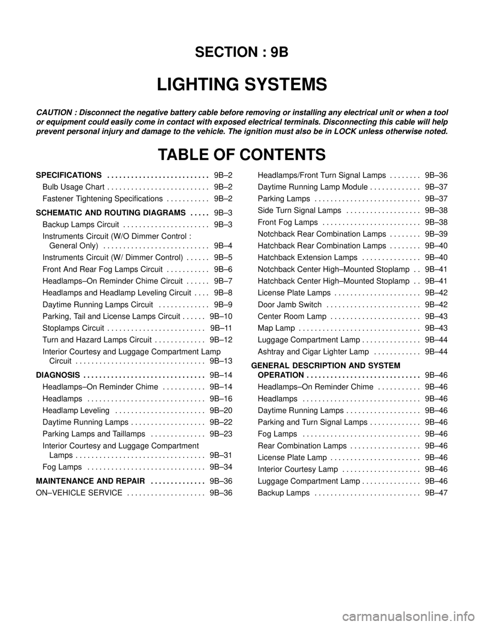
SECTION : 9B
LIGHTING SYSTEMS
CAUTION : Disconnect the negative battery cable before removing or installing any electrical unit or when a tool
or equipment could easily come in contact with exposed electrical terminals. Disconnecting this cable will help
prevent personal injury and damage to the vehicle. The ignition must also be in LOCK unless otherwise noted.
TABLE OF CONTENTS
SPECIFICATIONS9B–2 . . . . . . . . . . . . . . . . . . . . . . . . . .
Bulb Usage Chart 9B–2. . . . . . . . . . . . . . . . . . . . . . . . . .
Fastener Tightening Specifications 9B–2. . . . . . . . . . .
SCHEMATIC AND ROUTING DIAGRAMS9B–3 . . . . .
Backup Lamps Circuit 9B–3. . . . . . . . . . . . . . . . . . . . . .
Instruments Circuit (W/O Dimmer Control :
General Only) 9B–4. . . . . . . . . . . . . . . . . . . . . . . . . . .
Instruments Circuit (W/ Dimmer Control) 9B–5. . . . . .
Front And Rear Fog Lamps Circuit 9B–6. . . . . . . . . . .
Headlamps–On Reminder Chime Circuit 9B–7. . . . . .
Headlamps and Headlamp Leveling Circuit 9B–8. . . .
Daytime Running Lamps Circuit 9B–9. . . . . . . . . . . . .
Parking, Tail and License Lamps Circuit 9B–10. . . . . .
Stoplamps Circuit 9B–11. . . . . . . . . . . . . . . . . . . . . . . . .
Turn and Hazard Lamps Circuit 9B–12. . . . . . . . . . . . .
Interior Courtesy and Luggage Compartment Lamp
Circuit 9B–13. . . . . . . . . . . . . . . . . . . . . . . . . . . . . . . . .
DIAGNOSIS9B–14 . . . . . . . . . . . . . . . . . . . . . . . . . . . . . . .
Headlamps–On Reminder Chime 9B–14. . . . . . . . . . .
Headlamps 9B–16. . . . . . . . . . . . . . . . . . . . . . . . . . . . . .
Headlamp Leveling 9B–20. . . . . . . . . . . . . . . . . . . . . . .
Daytime Running Lamps 9B–22. . . . . . . . . . . . . . . . . . .
Parking Lamps and Taillamps 9B–23. . . . . . . . . . . . . .
Interior Courtesy and Luggage Compartment
Lamps 9B–31. . . . . . . . . . . . . . . . . . . . . . . . . . . . . . . . .
Fog Lamps 9B–34. . . . . . . . . . . . . . . . . . . . . . . . . . . . . .
MAINTENANCE AND REPAIR9B–36 . . . . . . . . . . . . . .
ON–VEHICLE SERVICE 9B–36. . . . . . . . . . . . . . . . . . . . Headlamps/Front Turn Signal Lamps 9B–36. . . . . . . .
Daytime Running Lamp Module 9B–37. . . . . . . . . . . . .
Parking Lamps 9B–37. . . . . . . . . . . . . . . . . . . . . . . . . . .
Side Turn Signal Lamps 9B–38. . . . . . . . . . . . . . . . . . .
Front Fog Lamps 9B–38. . . . . . . . . . . . . . . . . . . . . . . . .
Notchback Rear Combination Lamps 9B–39. . . . . . . .
Hatchback Rear Combination Lamps 9B–40. . . . . . . .
Hatchback Extension Lamps 9B–40. . . . . . . . . . . . . . .
Notchback Center High–Mounted Stoplamp 9B–41. .
Hatchback Center High–Mounted Stoplamp 9B–41. .
License Plate Lamps 9B–42. . . . . . . . . . . . . . . . . . . . . .
Door Jamb Switch 9B–42. . . . . . . . . . . . . . . . . . . . . . . .
Center Room Lamp 9B–43. . . . . . . . . . . . . . . . . . . . . . .
Map Lamp 9B–43. . . . . . . . . . . . . . . . . . . . . . . . . . . . . . .
Luggage Compartment Lamp 9B–44. . . . . . . . . . . . . . .
Ashtray and Cigar Lighter Lamp 9B–44. . . . . . . . . . . .
GENERAL DESCRIPTION AND SYSTEM
OPERATION9B–46 . . . . . . . . . . . . . . . . . . . . . . . . . . . . .
Headlamps–On Reminder Chime 9B–46. . . . . . . . . . .
Headlamps 9B–46. . . . . . . . . . . . . . . . . . . . . . . . . . . . . .
Daytime Running Lamps 9B–46. . . . . . . . . . . . . . . . . . .
Parking and Turn Signal Lamps 9B–46. . . . . . . . . . . . .
Fog Lamps 9B–46. . . . . . . . . . . . . . . . . . . . . . . . . . . . . .
Rear Combination Lamps 9B–46. . . . . . . . . . . . . . . . . .
License Plate Lamp 9B–46. . . . . . . . . . . . . . . . . . . . . . .
Interior Courtesy Lamp 9B–46. . . . . . . . . . . . . . . . . . . .
Luggage Compartment Lamp 9B–46. . . . . . . . . . . . . . .
Backup Lamps 9B–47. . . . . . . . . . . . . . . . . . . . . . . . . . .
Page 2272 of 2643
9B – 46ILITHING SYSTEMS
DAEWOO V–121 BL4
GENERAL DESCRIPTION
AND SYSTEM OPERATION
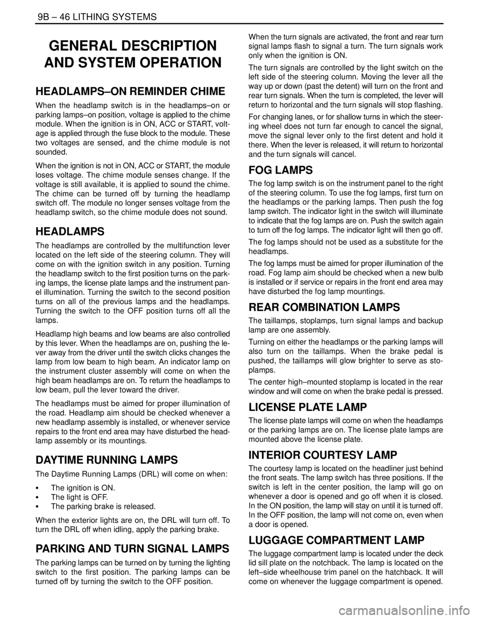
HEADLAMPS–ON REMINDER CHIME
When the headlamp switch is in the headlamps–on or
parking lamps–on position, voltage is applied to the chime
module. When the ignition is in ON, ACC or START, volt-
age is applied through the fuse block to the module. These
two voltages are sensed, and the chime module is not
sounded.
When the ignition is not in ON, ACC or START, the module
loses voltage. The chime module senses change. If the
voltage is still available, it is applied to sound the chime.
The chime can be turned off by turning the headlamp
switch off. The module no longer senses voltage from the
headlamp switch, so the chime module does not sound.
HEADLAMPS
The headlamps are controlled by the multifunction lever
located on the left side of the steering column. They will
come on with the ignition switch in any position. Turning
the headlamp switch to the first position turns on the park-
ing lamps, the license plate lamps and the instrument pan-
el illumination. Turning the switch to the second position
turns on all of the previous lamps and the headlamps.
Turning the switch to the OFF position turns off all the
lamps.
Headlamp high beams and low beams are also controlled
by this lever. When the headlamps are on, pushing the le-
ver away from the driver until the switch clicks changes the
lamp from low beam to high beam. An indicator lamp on
the instrument cluster assembly will come on when the
high beam headlamps are on. To return the headlamps to
low beam, pull the lever toward the driver.
The headlamps must be aimed for proper illumination of
the road. Headlamp aim should be checked whenever a
new headlamp assembly is installed, or whenever service
repairs to the front end area may have disturbed the head-
lamp assembly or its mountings.
DAYTIME RUNNING LAMPS
The Daytime Running Lamps (DRL) will come on when:
S The ignition is ON.
S The light is OFF.
S The parking brake is released.
When the exterior lights are on, the DRL will turn off. To
turn the DRL off when idling, apply the parking brake.
PARKING AND TURN SIGNAL LAMPS
The parking lamps can be turned on by turning the lighting
switch to the first position. The parking lamps can be
turned off by turning the switch to the OFF position.When the turn signals are activated, the front and rear turn
signal lamps flash to signal a turn. The turn signals work
only when the ignition is ON.
The turn signals are controlled by the light switch on the
left side of the steering column. Moving the lever all the
way up or down (past the detent) will turn on the front and
rear turn signals. When the turn is completed, the lever will
return to horizontal and the turn signals will stop flashing.
For changing lanes, or for shallow turns in which the steer-
ing wheel does not turn far enough to cancel the signal,
move the signal lever only to the first detent and hold it
there. When the lever is released, it will return to horizontal
and the turn signals will cancel.
FOG LAMPS
The fog lamp switch is on the instrument panel to the right
of the steering column. To use the fog lamps, first turn on
the headlamps or the parking lamps. Then push the fog
lamp switch. The indicator light in the switch will illuminate
to indicate that the fog lamps are on. Push the switch again
to turn off the fog lamps. The indicator light will then go off.
The fog lamps should not be used as a substitute for the
headlamps.
The fog lamps must be aimed for proper illumination of the
road. Fog lamp aim should be checked when a new bulb
is installed or if service or repairs in the front end area may
have disturbed the fog lamp mountings.
REAR COMBINATION LAMPS
The taillamps, stoplamps, turn signal lamps and backup
lamp are one assembly.
Turning on either the headlamps or the parking lamps will
also turn on the taillamps. When the brake pedal is
pushed, the taillamps will glow brighter to serve as sto-
plamps.
The center high–mounted stoplamp is located in the rear
window and will come on when the brake pedal is pressed.
LICENSE PLATE LAMP
The license plate lamps will come on when the headlamps
or the parking lamps are on. The license plate lamps are
mounted above the license plate.
INTERIOR COURTESY LAMP
The courtesy lamp is located on the headliner just behind
the front seats. The lamp switch has three positions. If the
switch is left in the center position, the lamp will go on
whenever a door is opened and go off when it is closed.
In the ON position, the lamp will stay on until it is turned off.
In the OFF position, the lamp will not come on, even when
a door is opened.
LUGGAGE COMPARTMENT LAMP
The luggage compartment lamp is located under the deck
lid sill plate on the notchback. The lamp is located on the
left–side wheelhouse trim panel on the hatchback. It will
come on whenever the luggage compartment is opened.
Page 2301 of 2643
9E – 2IINSTRUMENTATION/DRIVER INFORMATION
DAEWOO V–121 BL4
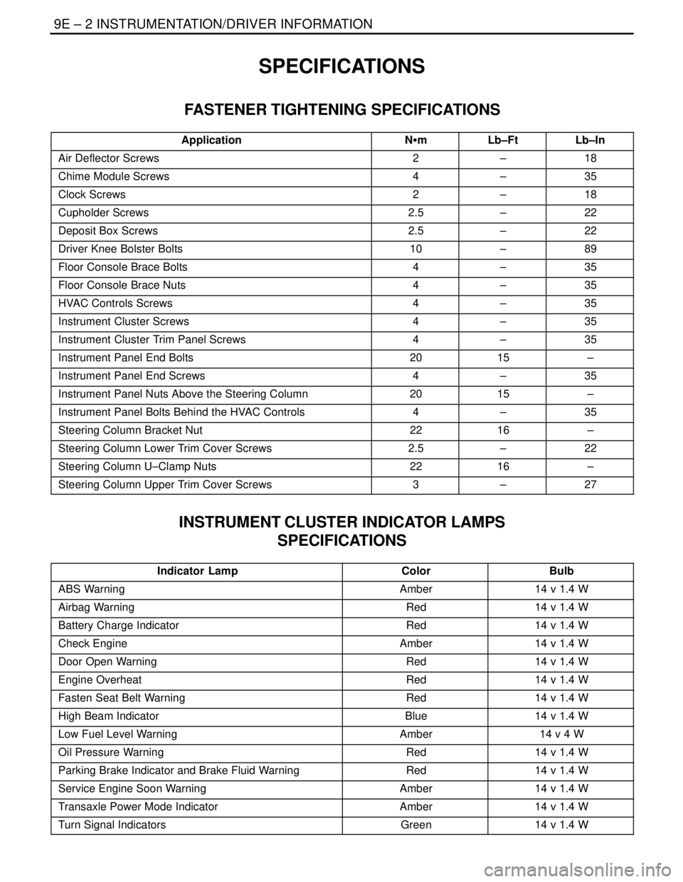
SPECIFICATIONS
FASTENER TIGHTENING SPECIFICATIONS
ApplicationNSmLb–FtLb–In
Air Deflector Screws2–18
Chime Module Screws4–35
Clock Screws2–18
Cupholder Screws2.5–22
Deposit Box Screws2.5–22
Driver Knee Bolster Bolts10–89
Floor Console Brace Bolts4–35
Floor Console Brace Nuts4–35
HVAC Controls Screws4–35
Instrument Cluster Screws4–35
Instrument Cluster Trim Panel Screws4–35
Instrument Panel End Bolts2015–
Instrument Panel End Screws4–35
Instrument Panel Nuts Above the Steering Column2015–
Instrument Panel Bolts Behind the HVAC Controls4–35
Steering Column Bracket Nut2216–
Steering Column Lower Trim Cover Screws2.5–22
Steering Column U–Clamp Nuts2216–
Steering Column Upper Trim Cover Screws3–27
INSTRUMENT CLUSTER INDICATOR LAMPS
SPECIFICATIONS
Indicator LampColorBulb
ABS WarningAmber14 v 1.4 W
Airbag WarningRed14 v 1.4 W
Battery Charge IndicatorRed14 v 1.4 W
Check EngineAmber14 v 1.4 W
Door Open WarningRed14 v 1.4 W
Engine OverheatRed14 v 1.4 W
Fasten Seat Belt WarningRed14 v 1.4 W
High Beam IndicatorBlue14 v 1.4 W
Low Fuel Level WarningAmber14 v 4 W
Oil Pressure WarningRed14 v 1.4 W
Parking Brake Indicator and Brake Fluid WarningRed14 v 1.4 W
Service Engine Soon WarningAmber14 v 1.4 W
Transaxle Power Mode IndicatorAmber14 v 1.4 W
Turn Signal IndicatorsGreen14 v 1.4 W
Page 2329 of 2643
9E – 30IINSTRUMENTATION/DRIVER INFORMATION
DAEWOO V–121 BL4
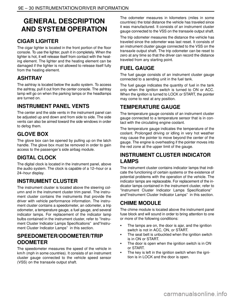
GENERAL DESCRIPTION
AND SYSTEM OPERATION
CIGAR LIGHTER
The cigar lighter is located in the front portion of the floor
console. To use the lighter, push it in completely. When the
lighter is hot, it will release itself from contact with the heat-
ing element. The lighter and the heating element can be
damaged if the lighter is not allowed to release itself fully
from the heating element.
ASHTRAY
The ashtray is located below the audio system. To access
the ashtray, pull it out from the center console. The ashtray
lamp will go on when the parking lamps or the headlamps
are turned on.
INSTRUMENT PANEL VENTS
The center and the side vents in the instrument panel can
be adjusted up and down and from side to side. The side
vents can also be aimed toward the side windows in order
to defog them.
GLOVE BOX
The glove box can be opened by pulling up on the latch
handle. The glove box must be removed in order to gain
access to the passenger’s side airbag module.
DIGTAL CLOCK
The digital clock is located in the instrument panel, above
the audio system. The clock is capable of a 12–hour or a
24–hour display.
INSTRUMENT CLUSTER
The instrument cluster is located above the steering col-
umn and in the instrument cluster trim panel. The instru-
ment cluster contains the instruments that provide the
driver with vehicle performance information. The instru-
ment cluster contains a speedometer, an odometer, a trip
odometer, a temperature gauge, a fuel gauge, and several
indicator lamps. For replacement of the indicator lamp
bulbs contained in the instrument cluster, refer to ”Instru-
ment Cluster Indicator Lamps Specifications” and”Instru-
ment Cluster Indicator Lamps” in this section.
SPEEDOMETER/ODOMETER/TRIP
ODOMETER
The speedometer measures the speed of the vehicle in
km/h (mph in some countries). It consists of an instrument
cluster gauge connected to the vehicle speed sensor
(VSS) on the transaxle output shaft.The odometer measures in kilometers (miles in some
countries) the total distance the vehicle has traveled since
it was manufactured. It consists of an instrument cluster
gauge connected to the VSS on the transaxle output shaft.
The trip odometer measures the distance the vehicle has
traveled since the odometer was last reset. It consists of
an instrument cluster gauge connected to the VSS on the
transaxle output shaft. The trip odometer can be reset to
zero at any time so that the driver can record the distance
traveled from any starting point.
FUEL GAUGE
The fuel gauge consists of an instrument cluster gauge
connected to a sending unit in the fuel tank.
The fuel gauge indicates the quantity of fuel in the tank
only when the ignition switch is turned to ON or ACC.
When the ignition is turned to LOCK or START, the pointer
may come to rest at any position.
TEMPERATURE GAUGE
The temperature gauge consists of an instrument cluster
gauge connected to a temperature sensor that is in con-
tact with the circulating engine coolant.
The temperature gauge indicates the temperature of the
coolant. Prolonged driving or idling in very hot weather
may cause the pointer to move beyond the center of the
gauge. The engine is overheating if the pointer moves into
the red zone at the upper limit of the gauge.
INSTRUMENT CLUSTER INDICATOR
LAMPS
The instrument cluster contains indicator lamps that indi-
cate the functioning of certain systems or the existence of
potential problems with the operation of the vehicle. The
indicator lamps are replaceable. For replacement of the in-
dicator lamps contained in the instrument cluster, refer to
”Instrument Cluster Indicator Lamps Specifications”
and”Instrument Cluster Indicator Lamps” in this section.
CHIME MODULE
The chime module is located above the instrument panel
fuse block and will sound in order to bring attention to one
or more of the following conditions:
S The lamps are on, the door is ajar, and the ignition
switch is not in ACC, ON, or START.
S The seat belt is unbuckled when the ignition switch
is in ON or START.
S The door is open when the ignition switch is in ON
or START.
S The key is left in the ignition switch when the igni-
tion is in LOCK and the door is open.
Page 2330 of 2643
SECTION : 9F
AUDIO SYSTEMS
CAUTION : Disconnect the negative battery cable before removing or installing any electrical unit or when a tool
or equipment could easily come in contact with exposed electrical terminals. Disconnecting this cable will help
prevent personal injury and damage to the vehicle. The ignition must also be in LOCK unless otherwise noted.
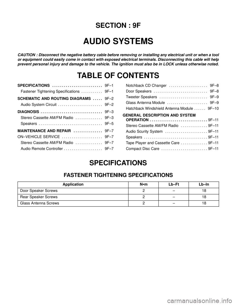
TABLE OF CONTENTS
SPECIFICATIONS9F–1 . . . . . . . . . . . . . . . . . . . . . . . . . .
Fastener Tightening Specifications 9F–1. . . . . . . . . . .
SCHEMATIC AND ROUTING DIAGRAMS9F–2 . . . . .
Audio System Circuit 9F–2. . . . . . . . . . . . . . . . . . . . . . .
DIAGNOSIS9F–3 . . . . . . . . . . . . . . . . . . . . . . . . . . . . . . . .
Stereo Cassette AM/FM Radio 9F–3. . . . . . . . . . . . . .
Speakers 9F–5. . . . . . . . . . . . . . . . . . . . . . . . . . . . . . . . .
MAINTENANCE AND REPAIR9F–7 . . . . . . . . . . . . . . .
ON–VEHICLE SERVICE 9F–7. . . . . . . . . . . . . . . . . . . . .
Stereo Cassette AM/FM Radio 9F–7. . . . . . . . . . . . . .
Audio Remote Controller 9F–7. . . . . . . . . . . . . . . . . . . . Notchback CD Changer 9F–8. . . . . . . . . . . . . . . . . . . .
Door Speakers 9F–8. . . . . . . . . . . . . . . . . . . . . . . . . . . .
Tweeter Speakers 9F–9. . . . . . . . . . . . . . . . . . . . . . . . .
Glass Antenna Module 9F–9. . . . . . . . . . . . . . . . . . . . .
Hatchback Windshield Antenna Module 9F–10. . . . . .
GENERAL DESCRIPTION AND SYSTEM
OPERATION9F–11 . . . . . . . . . . . . . . . . . . . . . . . . . . . . . .
Stereo Cassette AM/FM Radio 9F–11. . . . . . . . . . . . . .
Audio Scurity System 9F–11. . . . . . . . . . . . . . . . . . . . . .
Speakers 9F–11. . . . . . . . . . . . . . . . . . . . . . . . . . . . . . . . .
Tape Player and Cassette Care 9F–11. . . . . . . . . . . . . .
Compact Disc Care 9F–11. . . . . . . . . . . . . . . . . . . . . . . .
SPECIFICATIONS
FASTENER TIGHTENING SPECIFICATIONS
ApplicationNSmLb–FtLb–In
Door Speaker Screws2–18
Rear Speaker Screws2–18
Glass Antenna Screws2–18
Page 2341 of 2643
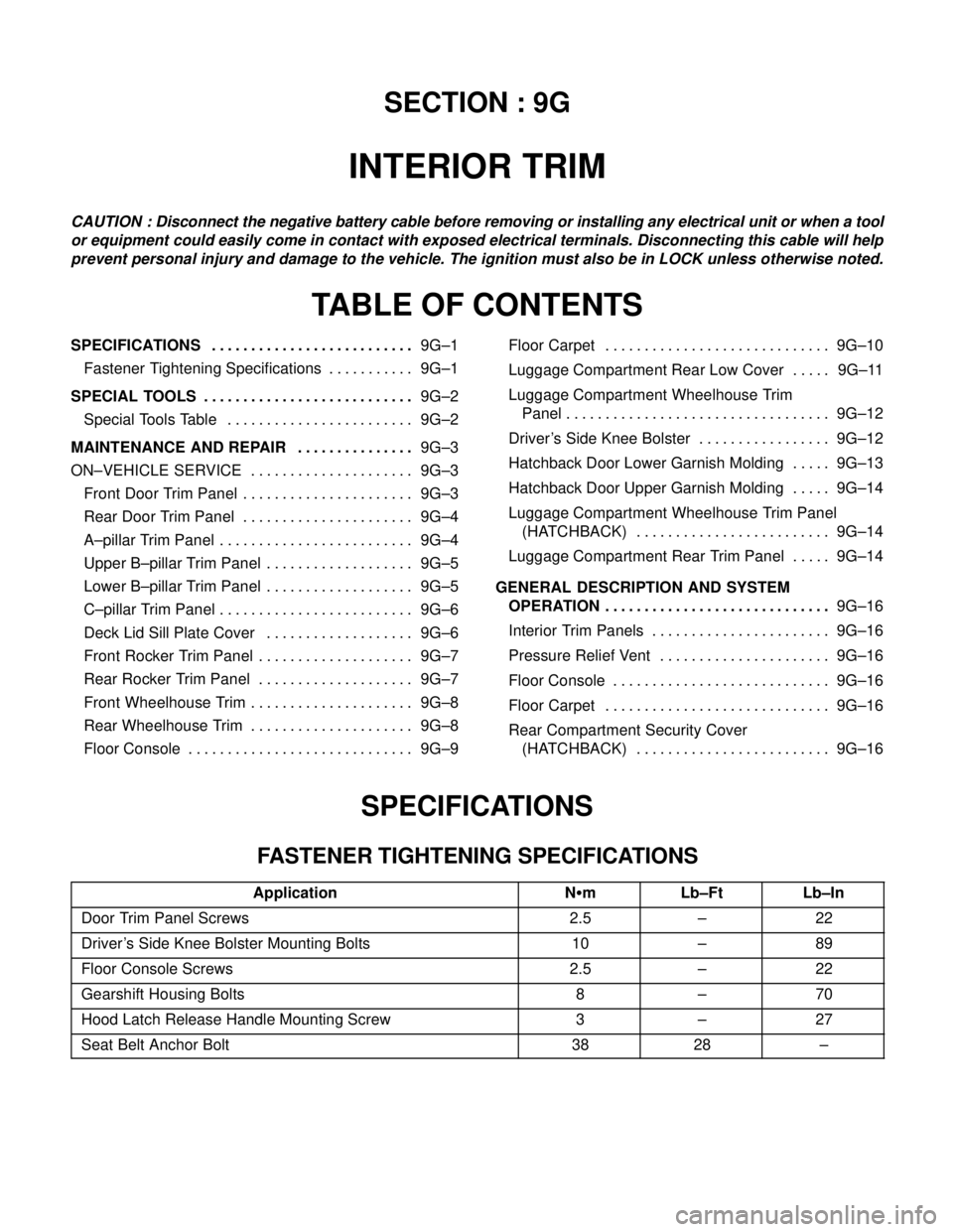
SECTION : 9G
INTERIOR TRIM
CAUTION : Disconnect the negative battery cable before removing or installing any electrical unit or when a tool
or equipment could easily come in contact with exposed electrical terminals. Disconnecting this cable will help
prevent personal injury and damage to the vehicle. The ignition must also be in LOCK unless otherwise noted.
TABLE OF CONTENTS
SPECIFICATIONS9G–1 . . . . . . . . . . . . . . . . . . . . . . . . . .
Fastener Tightening Specifications 9G–1. . . . . . . . . . .
SPECIAL TOOLS9G–2 . . . . . . . . . . . . . . . . . . . . . . . . . . .
Special Tools Table 9G–2. . . . . . . . . . . . . . . . . . . . . . . .
MAINTENANCE AND REPAIR9G–3 . . . . . . . . . . . . . . .
ON–VEHICLE SERVICE 9G–3. . . . . . . . . . . . . . . . . . . . .
Front Door Trim Panel 9G–3. . . . . . . . . . . . . . . . . . . . . .
Rear Door Trim Panel 9G–4. . . . . . . . . . . . . . . . . . . . . .
A–pillar Trim Panel 9G–4. . . . . . . . . . . . . . . . . . . . . . . . .
Upper B–pillar Trim Panel 9G–5. . . . . . . . . . . . . . . . . . .
Lower B–pillar Trim Panel 9G–5. . . . . . . . . . . . . . . . . . .
C–pillar Trim Panel 9G–6. . . . . . . . . . . . . . . . . . . . . . . . .
Deck Lid Sill Plate Cover 9G–6. . . . . . . . . . . . . . . . . . .
Front Rocker Trim Panel 9G–7. . . . . . . . . . . . . . . . . . . .
Rear Rocker Trim Panel 9G–7. . . . . . . . . . . . . . . . . . . .
Front Wheelhouse Trim 9G–8. . . . . . . . . . . . . . . . . . . . .
Rear Wheelhouse Trim 9G–8. . . . . . . . . . . . . . . . . . . . .
Floor Console 9G–9. . . . . . . . . . . . . . . . . . . . . . . . . . . . . Floor Carpet 9G–10. . . . . . . . . . . . . . . . . . . . . . . . . . . . .
Luggage Compartment Rear Low Cover 9G–11. . . . .
Luggage Compartment Wheelhouse Trim
Panel 9G–12. . . . . . . . . . . . . . . . . . . . . . . . . . . . . . . . . .
Driver’s Side Knee Bolster 9G–12. . . . . . . . . . . . . . . . .
Hatchback Door Lower Garnish Molding 9G–13. . . . .
Hatchback Door Upper Garnish Molding 9G–14. . . . .
Luggage Compartment Wheelhouse Trim Panel
(HATCHBACK) 9G–14. . . . . . . . . . . . . . . . . . . . . . . . .
Luggage Compartment Rear Trim Panel 9G–14. . . . .
GENERAL DESCRIPTION AND SYSTEM
OPERATION9G–16 . . . . . . . . . . . . . . . . . . . . . . . . . . . . .
Interior Trim Panels 9G–16. . . . . . . . . . . . . . . . . . . . . . .
Pressure Relief Vent 9G–16. . . . . . . . . . . . . . . . . . . . . .
Floor Console 9G–16. . . . . . . . . . . . . . . . . . . . . . . . . . . .
Floor Carpet 9G–16. . . . . . . . . . . . . . . . . . . . . . . . . . . . .
Rear Compartment Security Cover
(HATCHBACK) 9G–16. . . . . . . . . . . . . . . . . . . . . . . . .
SPECIFICATIONS
FASTENER TIGHTENING SPECIFICATIONS
ApplicationNSmLb–FtLb–In
Door Trim Panel Screws2.5–22
Driver’s Side Knee Bolster Mounting Bolts10–89
Floor Console Screws2.5–22
Gearshift Housing Bolts8–70
Hood Latch Release Handle Mounting Screw3–27
Seat Belt Anchor Bolt3828–
Page 2375 of 2643
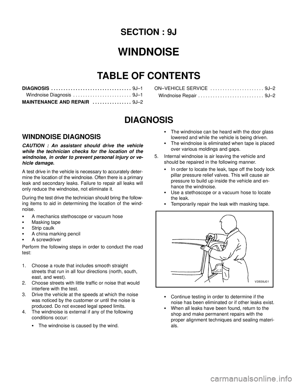
SECTION : 9J
WINDNOISE
TABLE OF CONTENTS
DIAGNOSIS9J–1 . . . . . . . . . . . . . . . . . . . . . . . . . . . . . . . . .
Windnoise Diagnosis 9J–1. . . . . . . . . . . . . . . . . . . . . . . .
MAINTENANCE AND REPAIR9J–2 . . . . . . . . . . . . . . . . ON–VEHICLE SERVICE 9J–2. . . . . . . . . . . . . . . . . . . . . .
Windnoise Repair 9J–2. . . . . . . . . . . . . . . . . . . . . . . . . . .
DIAGNOSIS
WINDNOISE DIAGNOSIS
CAUTION : An assistant should drive the vehicle
while the technician checks for the location of the
windnoise, in order to prevent personal injury or ve-
hicle damage.
A test drive in the vehicle is necessary to accurately deter-
mine the location of the windnoise. Often there is a primary
leak and secondary leaks. Failure to repair all leaks will
only reduce the windnoise, not eliminate it.
During the test drive the technician should bring the follow-
ing items to aid in determining the location of the wind-
noise.
S A mechanics stethoscope or vacuum hose
S Masking tape
S Strip caulk
S A china marking pencil
S A screwdriver
Perform the following steps in order to conduct the road
test:
1. Choose a route that includes smooth straight
streets that run in all four directions (north, south,
east, and west).
2. Choose streets with little traffic or noise that would
interfere with the test.
3. Drive the vehicle at the speeds at which the noise
was noticed by the customer or until the noise is
produced. Do not exceed legal speed limits.
4. The windnoise is external if any of the following
conditions occur:
S The windnoise is caused by the wind.S The windnoise can be heard with the door glass
lowered and while the vehicle is being driven.
S The windnoise is eliminated when tape is placed
over various moldings and gaps.
5. Internal windnoise is air leaving the vehicle and
should be repaired in the following manner.
S In order to locate the leak, tape off the body lock
pillar pressure relief valves. This will cause air
pressure to build up inside the vehicle and en-
hance the windnoise.
S Use a stethoscope or a vacuum hose to locate
the leak.
S Temporarily repair the leak with masking tape.
S Continue testing in order to determine if the
noise has been eliminated or if other leaks exist.
S When all leaks have been found, return to the
shop and make permanent repairs with the
proper alignment techniques and sealing materi-
als.