tires DAEWOO LACETTI 2004 Service Service Manual
[x] Cancel search | Manufacturer: DAEWOO, Model Year: 2004, Model line: LACETTI, Model: DAEWOO LACETTI 2004Pages: 2643, PDF Size: 80.54 MB
Page 952 of 2643
2D – 10IREAR SUSPENSION
DAEWOO V–121 BL4
Installation Procedure
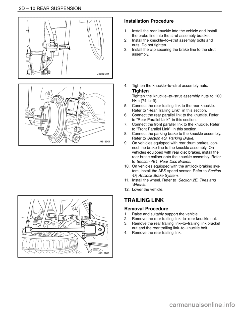
1. Install the rear knuckle into the vehicle and install
the brake line into the strut assembly bracket.
2. Install the knuckle–to–strut assembly bolts and
nuts. Do not tighten.
3. Install the clip securing the brake line to the strut
assembly.
4. Tighten the knuckle–to–strut assembly nuts.
Tighten
Tighten the knuckle–to–strut assembly nuts to 100
NSm (74 lb–ft).
5. Connect the rear trailing link to the rear knuckle.
Refer to ”Rear Trailing Link” in this section.
6. Connect the rear parallel link to the knuckle. Refer
to ”Rear Parallel Link” in this section.
7. Connect the front parallel link to the knuckle. Refer
to ”Front Parallel Link” in this section.
8. Connect the parking brake to the knuckle assembly.
Refer to Section 4G, Parking Brake.
9. On vehicles equipped with rear drum brakes, con-
nect the brake line to the knuckle assembly. On
vehicles equipped with rear disc brakes, install the
rear brake caliper onto the knuckle assembly. Refer
to Section 4E1, Rear Disc Brakes.
10. On vehicles equipped with the antilock braking sys-
tem, install the ABS speed sensor. Refer to Section
4F, Antilock Brake System.
11. Install the wheel. Refer to Section 2E, Tires and
Wheels.
12. Lower the vehicle.
TRAILING LINK
Removal Procedure
1. Raise and suitably support the vehicle.
2. Remove the rear trailing link–to–rear knuckle nut.
3. Remove the rear trailing link–to–trailing link bracket
nut and the rear trailing link–to–knuckle bolt.
4. Remove the rear trailing link.
Page 954 of 2643
2D – 12IREAR SUSPENSION
DAEWOO V–121 BL4
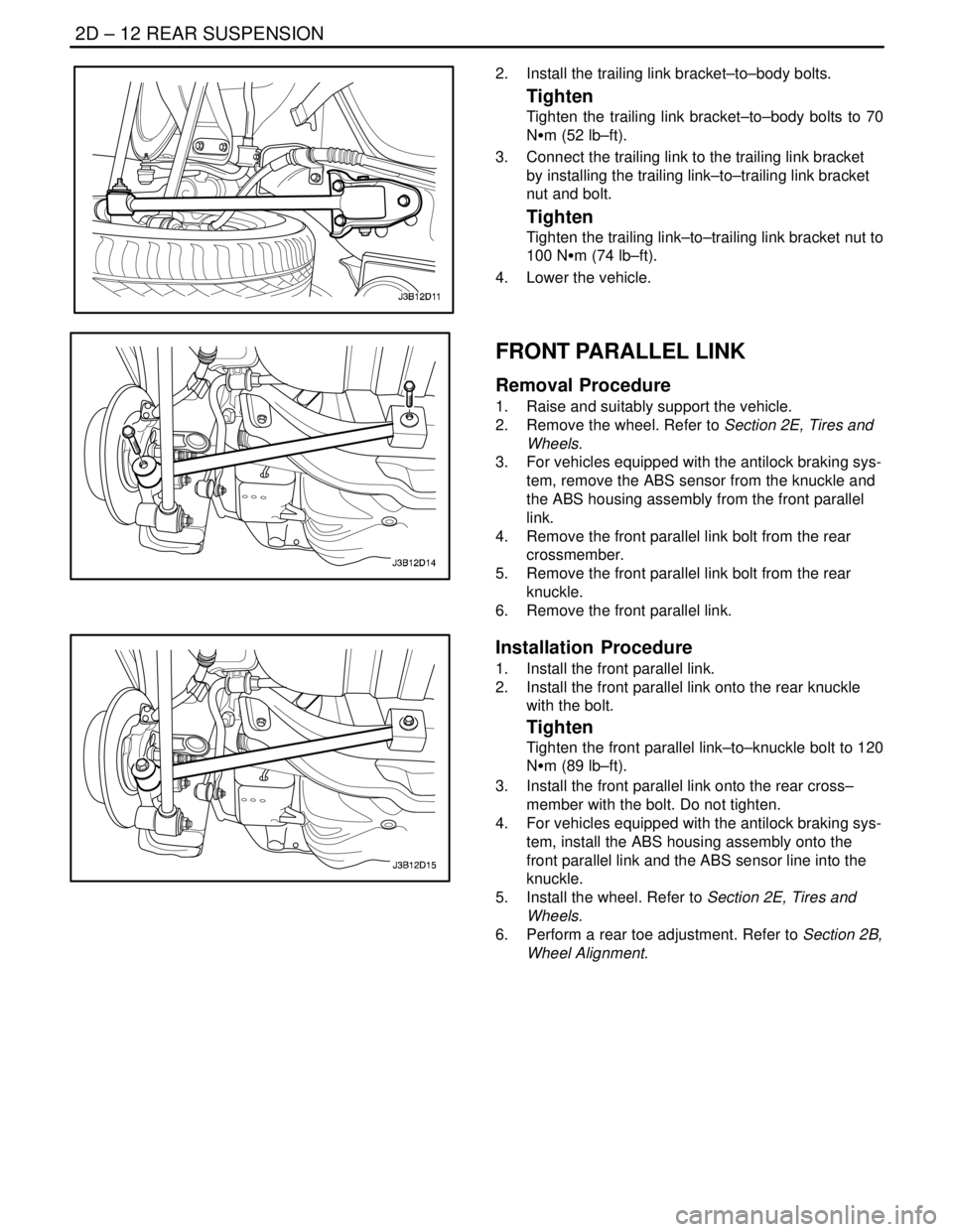
2. Install the trailing link bracket–to–body bolts.
Tighten
Tighten the trailing link bracket–to–body bolts to 70
NSm (52 lb–ft).
3. Connect the trailing link to the trailing link bracket
by installing the trailing link–to–trailing link bracket
nut and bolt.
Tighten
Tighten the trailing link–to–trailing link bracket nut to
100 NSm (74 lb–ft).
4. Lower the vehicle.
FRONT PARALLEL LINK
Removal Procedure
1. Raise and suitably support the vehicle.
2. Remove the wheel. Refer to Section 2E, Tires and
Wheels.
3. For vehicles equipped with the antilock braking sys-
tem, remove the ABS sensor from the knuckle and
the ABS housing assembly from the front parallel
link.
4. Remove the front parallel link bolt from the rear
crossmember.
5. Remove the front parallel link bolt from the rear
knuckle.
6. Remove the front parallel link.
Installation Procedure
1. Install the front parallel link.
2. Install the front parallel link onto the rear knuckle
with the bolt.
Tighten
Tighten the front parallel link–to–knuckle bolt to 120
NSm (89 lb–ft).
3. Install the front parallel link onto the rear cross–
member with the bolt. Do not tighten.
4. For vehicles equipped with the antilock braking sys-
tem, install the ABS housing assembly onto the
front parallel link and the ABS sensor line into the
knuckle.
5. Install the wheel. Refer to Section 2E, Tires and
Wheels.
6. Perform a rear toe adjustment. Refer to Section 2B,
Wheel Alignment.
Page 955 of 2643
REAR SUSPENSION 2D – 13
DAEWOO V–121 BL4
REAR PARALLEL LINK
Removal Procedure
1. Raise and suitably support the vehicle.
2. Remove the wheel. Refer to Section 2E, Tires and
Wheels.
Important : Before removing the parallel link–to–cross-
member bolt, mark the position of the adjuster cam in rela-
tion to the parallel link and the crossmember. This adjuster
cam must be placed in the same position when the parallel
link is installed on the vehicle to maintain the proper rear
toe.
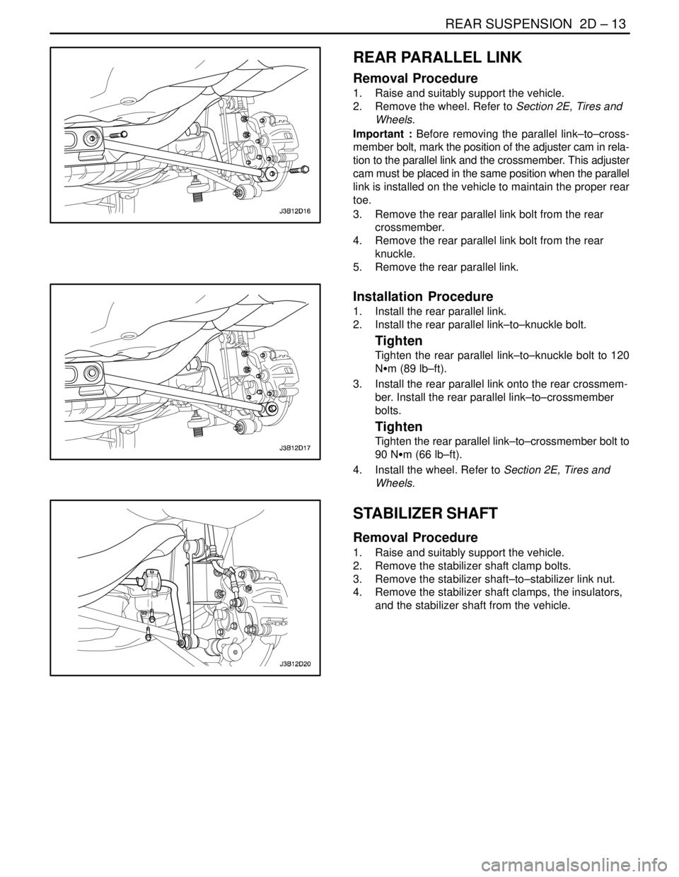
3. Remove the rear parallel link bolt from the rear
crossmember.
4. Remove the rear parallel link bolt from the rear
knuckle.
5. Remove the rear parallel link.
Installation Procedure
1. Install the rear parallel link.
2. Install the rear parallel link–to–knuckle bolt.
Tighten
Tighten the rear parallel link–to–knuckle bolt to 120
NSm (89 lb–ft).
3. Install the rear parallel link onto the rear crossmem-
ber. Install the rear parallel link–to–crossmember
bolts.
Tighten
Tighten the rear parallel link–to–crossmember bolt to
90 NSm (66 lb–ft).
4. Install the wheel. Refer to Section 2E, Tires and
Wheels.
STABILIZER SHAFT
Removal Procedure
1. Raise and suitably support the vehicle.
2. Remove the stabilizer shaft clamp bolts.
3. Remove the stabilizer shaft–to–stabilizer link nut.
4. Remove the stabilizer shaft clamps, the insulators,
and the stabilizer shaft from the vehicle.
Page 956 of 2643
2D – 14IREAR SUSPENSION
DAEWOO V–121 BL4
Installation Procedure
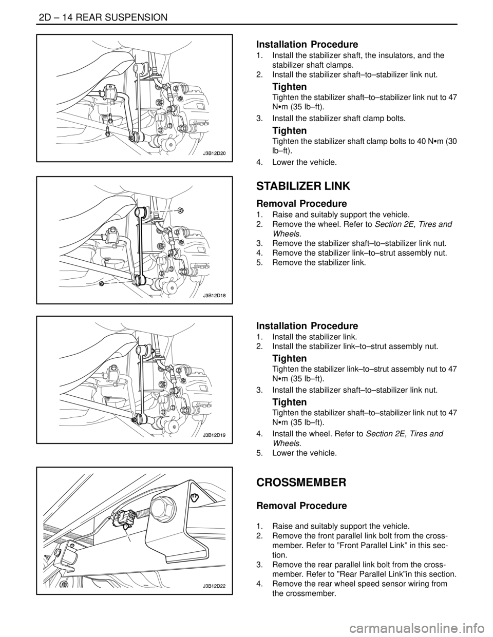
1. Install the stabilizer shaft, the insulators, and the
stabilizer shaft clamps.
2. Install the stabilizer shaft–to–stabilizer link nut.
Tighten
Tighten the stabilizer shaft–to–stabilizer link nut to 47
NSm (35 lb–ft).
3. Install the stabilizer shaft clamp bolts.
Tighten
Tighten the stabilizer shaft clamp bolts to 40 NSm (30
lb–ft).
4. Lower the vehicle.
STABILIZER LINK
Removal Procedure
1. Raise and suitably support the vehicle.
2. Remove the wheel. Refer to Section 2E, Tires and
Wheels.
3. Remove the stabilizer shaft–to–stabilizer link nut.
4. Remove the stabilizer link–to–strut assembly nut.
5. Remove the stabilizer link.
Installation Procedure
1. Install the stabilizer link.
2. Install the stabilizer link–to–strut assembly nut.
Tighten
Tighten the stabilizer link–to–strut assembly nut to 47
NSm (35 lb–ft).
3. Install the stabilizer shaft–to–stabilizer link nut.
Tighten
Tighten the stabilizer shaft–to–stabilizer link nut to 47
NSm (35 lb–ft).
4. Install the wheel. Refer to Section 2E, Tires and
Wheels.
5. Lower the vehicle.
CROSSMEMBER
Removal Procedure
1. Raise and suitably support the vehicle.
2. Remove the front parallel link bolt from the cross-
member. Refer to ”Front Parallel Link” in this sec-
tion.
3. Remove the rear parallel link bolt from the cross-
member. Refer to ”Rear Parallel Link”in this section.
4. Remove the rear wheel speed sensor wiring from
the crossmember.
Page 957 of 2643
REAR SUSPENSION 2D – 15
DAEWOO V–121 BL4
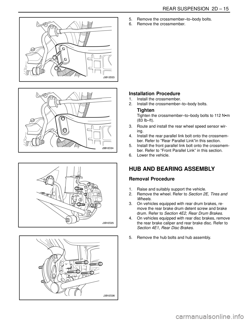
5. Remove the crossmember–to–body bolts.
6. Remove the crossmember.
Installation Procedure
1. Install the crossmember.
2. Install the crossmember–to–body bolts.
Tighten
Tighten the crossmember–to–body bolts to 112 NSm
(83 lb–ft).
3. Route and install the rear wheel speed sensor wir-
ing.
4. Install the rear parallel link bolt onto the crossmem-
ber. Refer to ”Rear Parallel Link”in this section.
5. Install the front parallel link bolt onto the crossmem-
ber. Refer to ”Front Parallel Link” in this section.
6. Lower the vehicle.
HUB AND BEARING ASSEMBLY
Removal Procedure
1. Raise and suitably support the vehicle.
2. Remove the wheel. Refer to Section 2E, Tires and
Wheels.
3. On vehicles equipped with rear drum brakes, re-
move the rear brake drum detent screw and brake
drum. Refer to Section 4E2, Rear Drum Brakes.
4. On vehicles equipped with rear disc brakes, remove
the rear brake caliper and rear brake disc. Refer to
Section 4E1, Rear Disc Brakes.
5. Remove the hub bolts and hub assembly.
Page 958 of 2643
2D – 16IREAR SUSPENSION
DAEWOO V–121 BL4
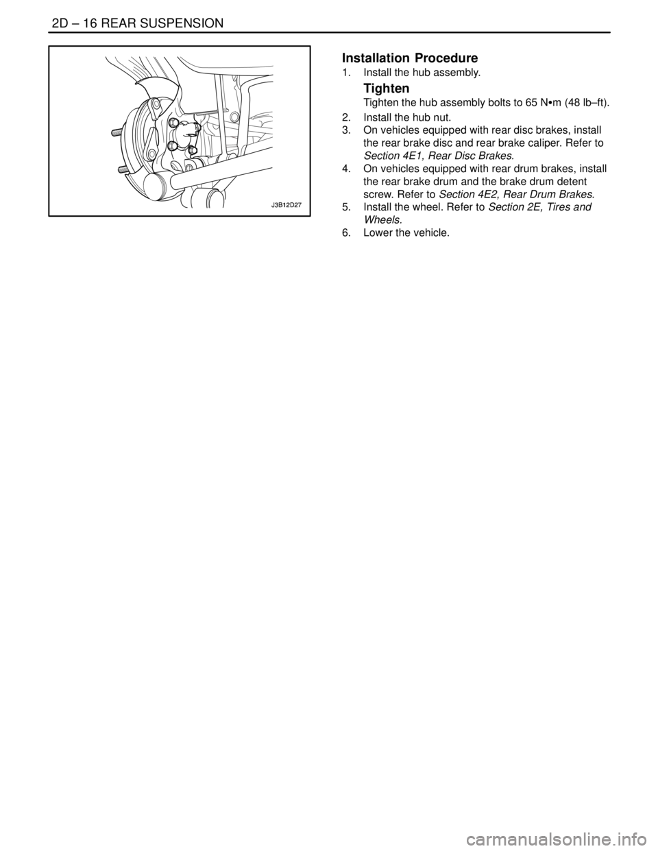
Installation Procedure
1. Install the hub assembly.
Tighten
Tighten the hub assembly bolts to 65 NSm (48 lb–ft).
2. Install the hub nut.
3. On vehicles equipped with rear disc brakes, install
the rear brake disc and rear brake caliper. Refer to
Section 4E1, Rear Disc Brakes.
4. On vehicles equipped with rear drum brakes, install
the rear brake drum and the brake drum detent
screw. Refer to Section 4E2, Rear Drum Brakes.
5. Install the wheel. Refer to Section 2E, Tires and
Wheels.
6. Lower the vehicle.
Page 963 of 2643

SECTION : 2E
TIRES AND WHEELS
TABLE OF CONTENTS
SPECIFICATIONS2E–1 . . . . . . . . . . . . . . . . . . . . . . . . . .
Tire Size and Pressure Specifications 2E–1. . . . . . . .
Inflation Pressure Conversion Specifications 2E–2. .
Fastener Tightening Specifications 2E–2. . . . . . . . . . .
DIAGNOSIS2E–2 . . . . . . . . . . . . . . . . . . . . . . . . . . . . . . . .
Wheel Runout 2E–2. . . . . . . . . . . . . . . . . . . . . . . . . . . . .
MAINTENANCE AND REPAIR2E–3 . . . . . . . . . . . . . . .
ON–VEHICLE SERVICE 2E–3. . . . . . . . . . . . . . . . . . . . .
Wheel 2E–3. . . . . . . . . . . . . . . . . . . . . . . . . . . . . . . . . . . .
On–Vehicle Balancing 2E–4. . . . . . . . . . . . . . . . . . . . . .
UNIT REPAIR 2E–5. . . . . . . . . . . . . . . . . . . . . . . . . . . . . .
Alloy Wheel Porosity 2E–5. . . . . . . . . . . . . . . . . . . . . . .
Alloy Wheel Refinishing 2E–5. . . . . . . . . . . . . . . . . . . . .
Off–Vehicle Balancing 2E–7. . . . . . . . . . . . . . . . . . . . . . Correcting Non–Uniform Tires 2E–7. . . . . . . . . . . . . . .
Tire and Wheel Match–Mounting 2E–8. . . . . . . . . . . . .
Tire Mounting and Dismounting 2E–8. . . . . . . . . . . . . .
GENERAL DESCRIPTION AND SYSTEM
OPERATION 2E–9 . . . . . . . . . . . . . . . . . . . . . . . . . . . . .
Tire and Wheel Balancing 2E–9. . . . . . . . . . . . . . . . . . .
Tire Chain Usage 2E–9. . . . . . . . . . . . . . . . . . . . . . . . . .
Replacement Tires 2E–10. . . . . . . . . . . . . . . . . . . . . . . .
All Season Tires 2E–10. . . . . . . . . . . . . . . . . . . . . . . . . .
Passenger Metric Sized Tires 2E–10. . . . . . . . . . . . . .
Tire Label 2E–10. . . . . . . . . . . . . . . . . . . . . . . . . . . . . . . .
Spare Tire 2E–10. . . . . . . . . . . . . . . . . . . . . . . . . . . . . . .
Wheels 2E–10. . . . . . . . . . . . . . . . . . . . . . . . . . . . . . . . . .
Inflation o Tires 2E–11. . . . . . . . . . . . . . . . . . . . . . . . . . .
SPECIFICATIONS
TIRE SIZE AND PRESSURE SPECIFICATIONS
Inflation Pressure at Full Load
TiresWheelFrontRear
kPapsikPapsi
175 / 70R145.5J x 14(Steel)2053020530
175 / 70R145.5J x 14(Alloy)2053020530
T125 / 70D154T x 154156041560
185 / 65R145.5J x 14(Steel)2053020530
185 / 65R145.5J x 14(Alloy)2053020530
T125 / 70D154T x 154156041560
195 / 55R156J x 15(Steel)2053020530
195 / 55R156J x 15(Alloy)2053020530
195 / 55R156J x 15
(Alloy, Sporty)2053020530
T125 / 70D154T x 154156041560
Page 964 of 2643
2E – 2ITIRES AND WHEELS
DAEWOO V–121 BL4
INFLATION PRESSURE CONVERSION SPECIFICATIONS
kPaPsikPaPsikPaPsi
140201852723534
145211902824035
155222002925036
160232053027540
165242153131045
170252203234550
FASTENER TIGHTENING SPECIFICATIONS
ApplicationNSmLb–FtLb–In
Wheel Bolt (Alloy Wheel)10074–
Wheel Bolt (Steel Wheel)10074–
DIAGNOSIS
WHEEL RUNOUT
Measure wheel runout with an accurate dial indicator.
Measurements may be taken with the wheels either on or
off the vehicle, using an accurate mounting surface such
as a wheel balancer. Measurements may be taken with or
without the tire mounted on the wheel.
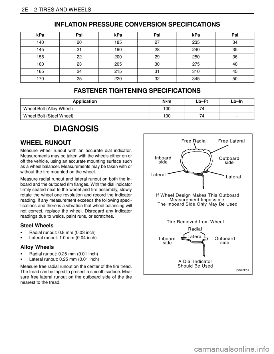
Measure radial runout and lateral runout on both the in-
board and the outboard rim flanges. With the dial indicator
firmly seated next to the wheel and tire assembly, slowly
rotate the wheel one revolution and record the indicator
reading. If any measurement exceeds the following speci-
fications and there is a vibration that wheel balancing will
not correct, replace the wheel. Disregard any indicator
readings due to welds, paint runs, or scratches.
Steel Wheels
S Radial runout: 0.8 mm (0.03 inch)
S Lateral runout: 1.0 mm (0.04 inch)
Alloy Wheels
S Radial runout: 0.25 mm (0.01 inch)
S Lateral runout: 0.25 mm (0.01 inch)
Measure free radial runout on the center of the tire tread.
The tread can be taped to present a smooth surface. Mea-
sure free lateral runout on the outboard side of the tire
nearest to the tread.
Page 965 of 2643

TIRES AND WHEELS 2E – 3
DAEWOO V–121 BL4
MAINTENANCE AND REPAIR
ON–VEHICLE SERVICE
WHEEL
Removal Procedure
1. Loosen the wheel bolts.
2. Raise and suitably support the vehicle.
3. Remove the wheel bolts.
Notice : Never use heat to loosen a tight wheel. It can
shorten the life of the wheel, the wheel nuts and the wheel
bearings. Excessive force, such as hammering the wheel
or tire, can also cause damage and is not recommended.
Slight tapping of the wheel sidewall with one’s hand or with
a rubber mallet is acceptable.
4. Remove the wheel.
Difficulty in removing the wheels from the vehicle can be
due to foreign material or to a tight fit between the wheel
centerhole and the hub or the rotor. These wheels can be
removed by
5. Retightening the wheel bolts on the affected wheel
and then loosening the wheel bolts by two turns.
6. Lowering the vehicle and rocking it from side to side
as hard as possible, using one or more person’s
body weight to loosen the wheel.
7. Raising the vehicle and removing the wheel.
CAUTION : Do not allow the penetrating oil to get on
the vertical surfaces between the wheel and the drum
(or rotor) because penetrating oil in this area could
cause the wheel to work loose as the vehicle is driven,
resulting in loss of control and an injury accident.
Penetrating oil is not effective in removing tight wheels. If
it is used, however, apply it sparingly and only to the
wheel’s centerhole area.
Installation Procedure
Notice : Before installing the wheels, remove any buildup
of corrosion on the wheel mounting surface and the brake
drum or the rotor mounting surface by scraping and brush-
ing them with a wire brush. Installing the wheels without
good metal–to–metal contact at the mounting surfaces
can cause the wheel nuts to loosen, which can later allow
a wheel to come off while the vehicle is moving. Wheel
bolts must be tightened in sequence and to the proper
torque to avoid bending the wheel, the brake drum or the
rotor.
1. Mount the wheel.
2. Install the wheel bolts in the sequence shown. Do
not tighten the wheel bolts.
3. Lower the vehicle.
Tighten
Tighten the wheel bolts to 100 NSm (74 lb–ft).
Page 966 of 2643
2E – 4ITIRES AND WHEELS
DAEWOO V–121 BL4
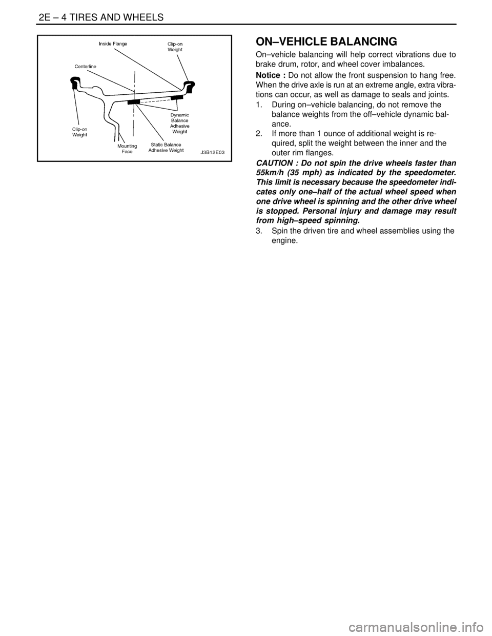
ON–VEHICLE BALANCING
On–vehicle balancing will help correct vibrations due to
brake drum, rotor, and wheel cover imbalances.
Notice : Do not allow the front suspension to hang free.
When the drive axle is run at an extreme angle, extra vibra-
tions can occur, as well as damage to seals and joints.
1. During on–vehicle balancing, do not remove the
balance weights from the off–vehicle dynamic bal-
ance.
2. If more than 1 ounce of additional weight is re-
quired, split the weight between the inner and the
outer rim flanges.
CAUTION : Do not spin the drive wheels faster than
55km/h (35 mph) as indicated by the speedometer.
This limit is necessary because the speedometer indi-
cates only one–half of the actual wheel speed when
one drive wheel is spinning and the other drive wheel
is stopped. Personal injury and damage may result
from high–speed spinning.
3. Spin the driven tire and wheel assemblies using the
engine.