wheel bolts DAEWOO LACETTI 2004 Service Manual Online
[x] Cancel search | Manufacturer: DAEWOO, Model Year: 2004, Model line: LACETTI, Model: DAEWOO LACETTI 2004Pages: 2643, PDF Size: 80.54 MB
Page 2415 of 2643

9O – 4IBUMPERS AND FASCIAS
DAEWOO V–121 BL4
Installation Procedure
1. Install the energy absorber.
2. Install the front bumper fascia. Refer to ”Front
Bumper Fascia” in this section.
FRONT BUMPER IMPACT BAR
Removal Procedure
1. Disconnect the electrical connector.
2. Remove the front bumper fascia. Refer to ”Front
Bumper Fascia” in this section.
3. Remove the front bumper energy absorber. Refer
to ”Front Bumper Energy Absorber” in this section.
4. Remove the bolts and the front bumper impact bar.
Installation Procedure
Notice : Dissimilar metals in direct contact with each other
may corrode rapidly. Make sure to use the correct fasten-
ers to prevent premature corrosion.
1. Install the front impact bar with the bolts.
Tighten
Tighten the front impact bar bolts to 39 NSm (29 lb–ft).
2. Install the front bumper energy absorber. Refer to
”Front Bumper Energy Absorber” in this section.
3. Install the front bumper fascia. Refer to ”Front
Bumper Fascia” in this section.
4. Connect the electrical connector.
NOTCHBACK REAR BUMPER
FASCIA
Removal Procedure
1. Remove the rear wheels. Refer to Section 2E,
Tires and Wheels.
2. Remove the screws and the mud guards.
3. Remove the screws and the splash shields.
4. Remove the screws behind the fascia.
Page 2417 of 2643

9O – 6IBUMPERS AND FASCIAS
DAEWOO V–121 BL4
4. Install the screws behind the fascia.
5. Install the splash shields with the screws.
6. Install the mud guards with the screws.
7. Install the rear wheels. Refer to Section 2E, Tires
and Wheels.
HATCHBACK REAR BUMPER
FASCIA
Removal Procedure
1. Remove the rear wheels. Refer to Section 2E,
Tires and Wheels.
2. Remove the screws and the splash shields.
3. Remove the screws behind the fascia.
4. Remove the luggage compartment wheelhouse trim
panels. Refer to Section 9G, Interior Trim.
5. Remove the bolts and the nuts in the luggage
compartment.
6. Remove the screws.
7. Remove the rear bumper fascia.
Page 2418 of 2643

BUMPERS AND FASCIAS 9O – 7
DAEWOO V–121 BL4
Installation Procedure
1. Install the rear bumper fascia with the screws.
2. Install the bolts and the nuts in the luggage
compartment.
3. Install the luggage compartment wheelhouse trim
panels. Refer to Section 9G, Interior Trim.
4. Install the screws behind the fascia.
5. Install the splash shields with the screws.
6. Install the rear wheels. Refer to Section 2E, Tires
and Wheels.
REAR BUMPER IMPACT BAR
Removal Procedure
1. Remove the rear bumper fascia. Refer to ”Rear
Bumper Fascia” in this section.
2. Remove the screws and the impact bar.
Page 2462 of 2643
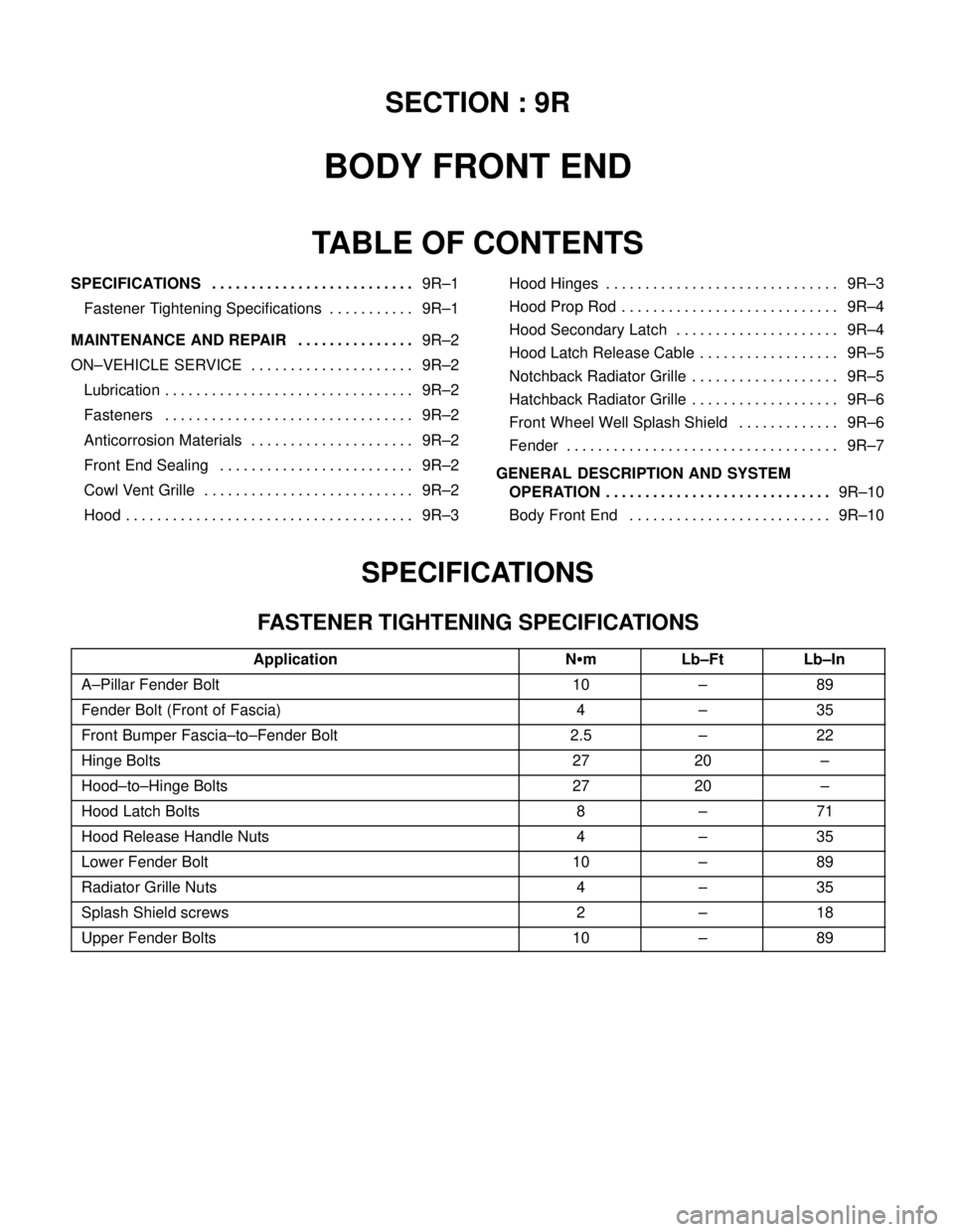
SECTION : 9R
BODY FRONT END
TABLE OF CONTENTS
SPECIFICATIONS9R–1 . . . . . . . . . . . . . . . . . . . . . . . . . .
Fastener Tightening Specifications 9R–1. . . . . . . . . . .
MAINTENANCE AND REPAIR9R–2 . . . . . . . . . . . . . . .
ON–VEHICLE SERVICE 9R–2. . . . . . . . . . . . . . . . . . . . .
Lubrication 9R–2. . . . . . . . . . . . . . . . . . . . . . . . . . . . . . . .
Fasteners 9R–2. . . . . . . . . . . . . . . . . . . . . . . . . . . . . . . .
Anticorrosion Materials 9R–2. . . . . . . . . . . . . . . . . . . . .
Front End Sealing 9R–2. . . . . . . . . . . . . . . . . . . . . . . . .
Cowl Vent Grille 9R–2. . . . . . . . . . . . . . . . . . . . . . . . . . .
Hood 9R–3. . . . . . . . . . . . . . . . . . . . . . . . . . . . . . . . . . . . . Hood Hinges 9R–3. . . . . . . . . . . . . . . . . . . . . . . . . . . . . .
Hood Prop Rod 9R–4. . . . . . . . . . . . . . . . . . . . . . . . . . . .
Hood Secondary Latch 9R–4. . . . . . . . . . . . . . . . . . . . .
Hood Latch Release Cable 9R–5. . . . . . . . . . . . . . . . . .
Notchback Radiator Grille 9R–5. . . . . . . . . . . . . . . . . . .
Hatchback Radiator Grille 9R–6. . . . . . . . . . . . . . . . . . .
Front Wheel Well Splash Shield 9R–6. . . . . . . . . . . . .
Fender 9R–7. . . . . . . . . . . . . . . . . . . . . . . . . . . . . . . . . . .
GENERAL DESCRIPTION AND SYSTEM
OPERATION9R–10 . . . . . . . . . . . . . . . . . . . . . . . . . . . . .
Body Front End 9R–10. . . . . . . . . . . . . . . . . . . . . . . . . .
SPECIFICATIONS
FASTENER TIGHTENING SPECIFICATIONS
ApplicationNSmLb–FtLb–In
A–Pillar Fender Bolt10–89
Fender Bolt (Front of Fascia)4–35
Front Bumper Fascia–to–Fender Bolt2.5–22
Hinge Bolts2720–
Hood–to–Hinge Bolts2720–
Hood Latch Bolts8–71
Hood Release Handle Nuts4–35
Lower Fender Bolt10–89
Radiator Grille Nuts4–35
Splash Shield screws2–18
Upper Fender Bolts10–89
Page 2468 of 2643
BODY FRONT END 9R – 7
DAEWOO V–121 BL4
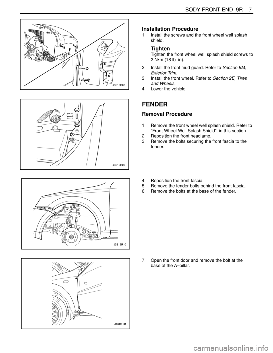
Installation Procedure
1. Install the screws and the front wheel well splash
shield.
Tighten
Tighten the front wheel well splash shield screws to
2 NSm (18 lb–in).
2. Install the front mud guard. Refer to Section 9M,
Exterior Trim.
3. Install the front wheel. Refer to Section 2E, Tires
and Wheels.
4. Lower the vehicle.
FENDER
Removal Procedure
1. Remove the front wheel well splash shield. Refer to
”Front Wheel Well Splash Shield” in this section.
2. Reposition the front headlamp.
3. Remove the bolts securing the front fascia to the
fender.
4. Reposition the front fascia.
5. Remove the fender bolts behind the front fascia.
6. Remove the bolts at the base of the fender.
7. Open the front door and remove the bolt at the
base of the A–pillar.
Page 2470 of 2643
BODY FRONT END 9R – 9
DAEWOO V–121 BL4
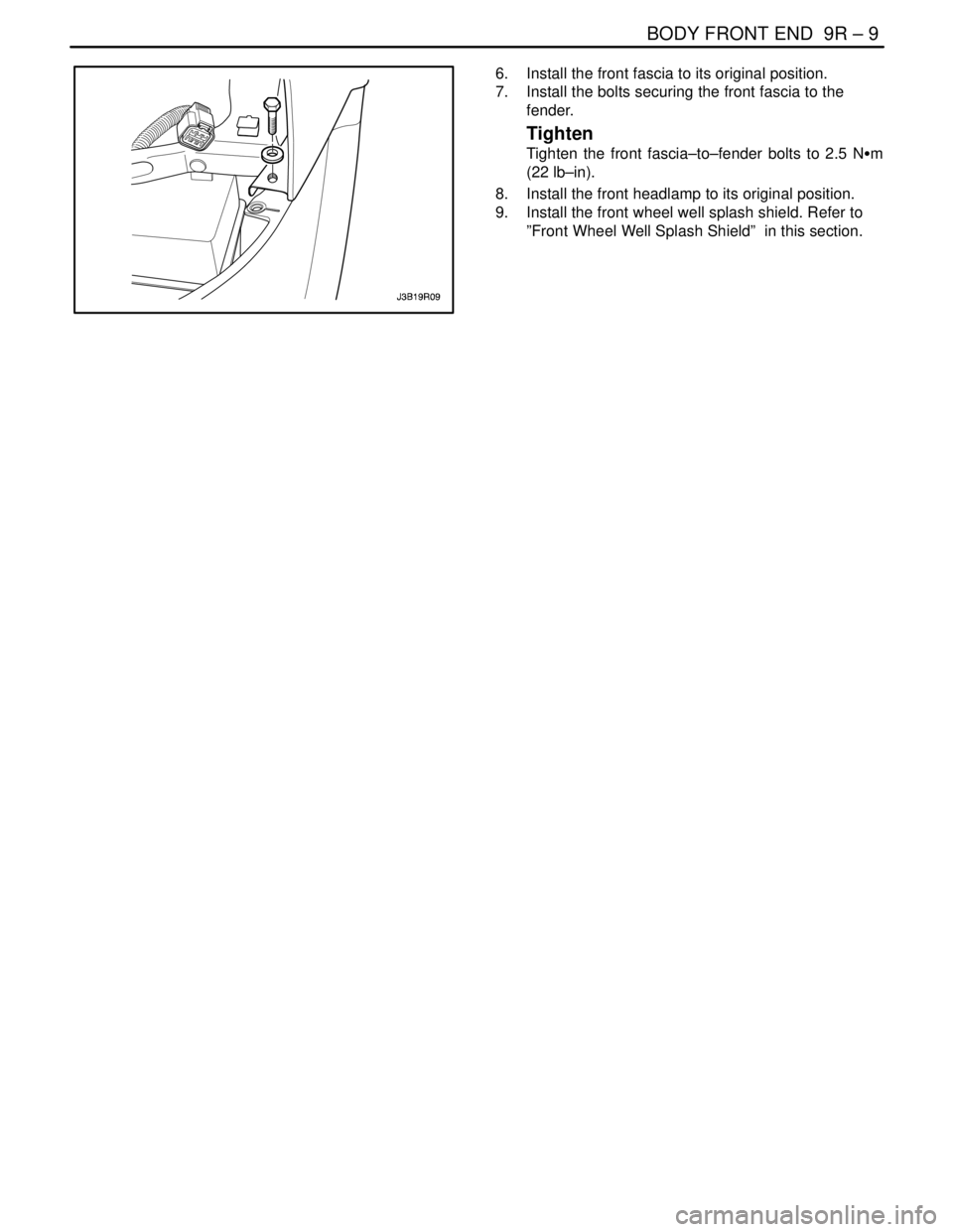
6. Install the front fascia to its original position.
7. Install the bolts securing the front fascia to the
fender.
Tighten
Tighten the front fascia–to–fender bolts to 2.5 NSm
(22 lb–in).
8. Install the front headlamp to its original position.
9. Install the front wheel well splash shield. Refer to
”Front Wheel Well Splash Shield” in this section.
Page 2475 of 2643
9S – 4IBODY REAR END
DAEWOO V–121 BL4
8. Install the lower B–pillar seat belt anchor with the
bolt.
Tighten
Tighten the lower B–pillar seat belt anchor bolt to 38
NSm (28 lb–ft).
9. Connect the cable to the fuel filler door.
10. Install the luggage compartment wheelhouse trim
panels and the luggage compartment rear trim pan-
el. Refer to Section 9G, Interior Trim.
11. Close the luggage compartment.
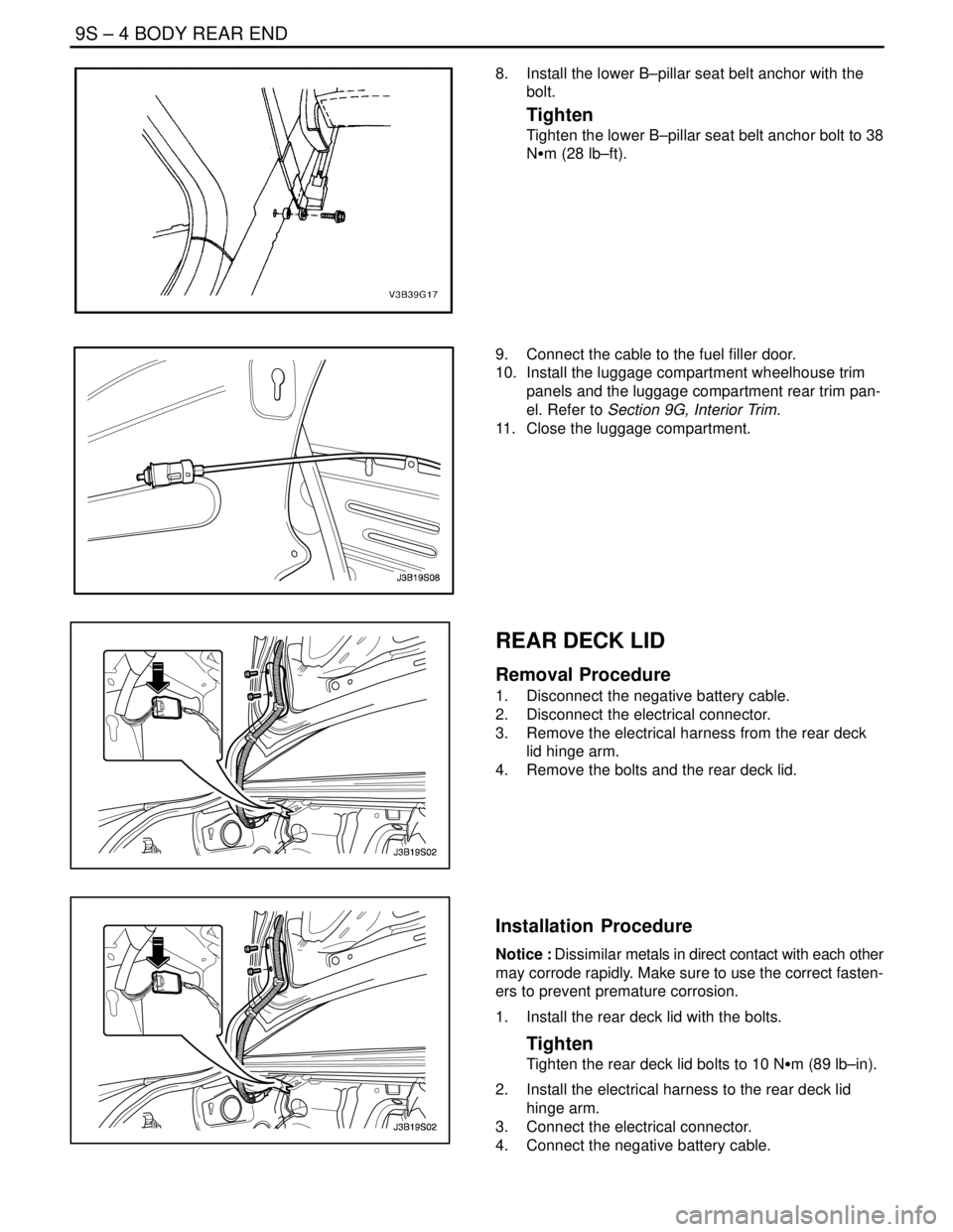
REAR DECK LID
Removal Procedure
1. Disconnect the negative battery cable.
2. Disconnect the electrical connector.
3. Remove the electrical harness from the rear deck
lid hinge arm.
4. Remove the bolts and the rear deck lid.
Installation Procedure
Notice : Dissimilar metals in direct contact with each other
may corrode rapidly. Make sure to use the correct fasten-
ers to prevent premature corrosion.
1. Install the rear deck lid with the bolts.
Tighten
Tighten the rear deck lid bolts to 10 NSm (89 lb–in).
2. Install the electrical harness to the rear deck lid
hinge arm.
3. Connect the electrical connector.
4. Connect the negative battery cable.
Page 2579 of 2643
7–2 FENDER, HOOD, TAILGATE AND TRUNK LID NUBIRA/LACETTI
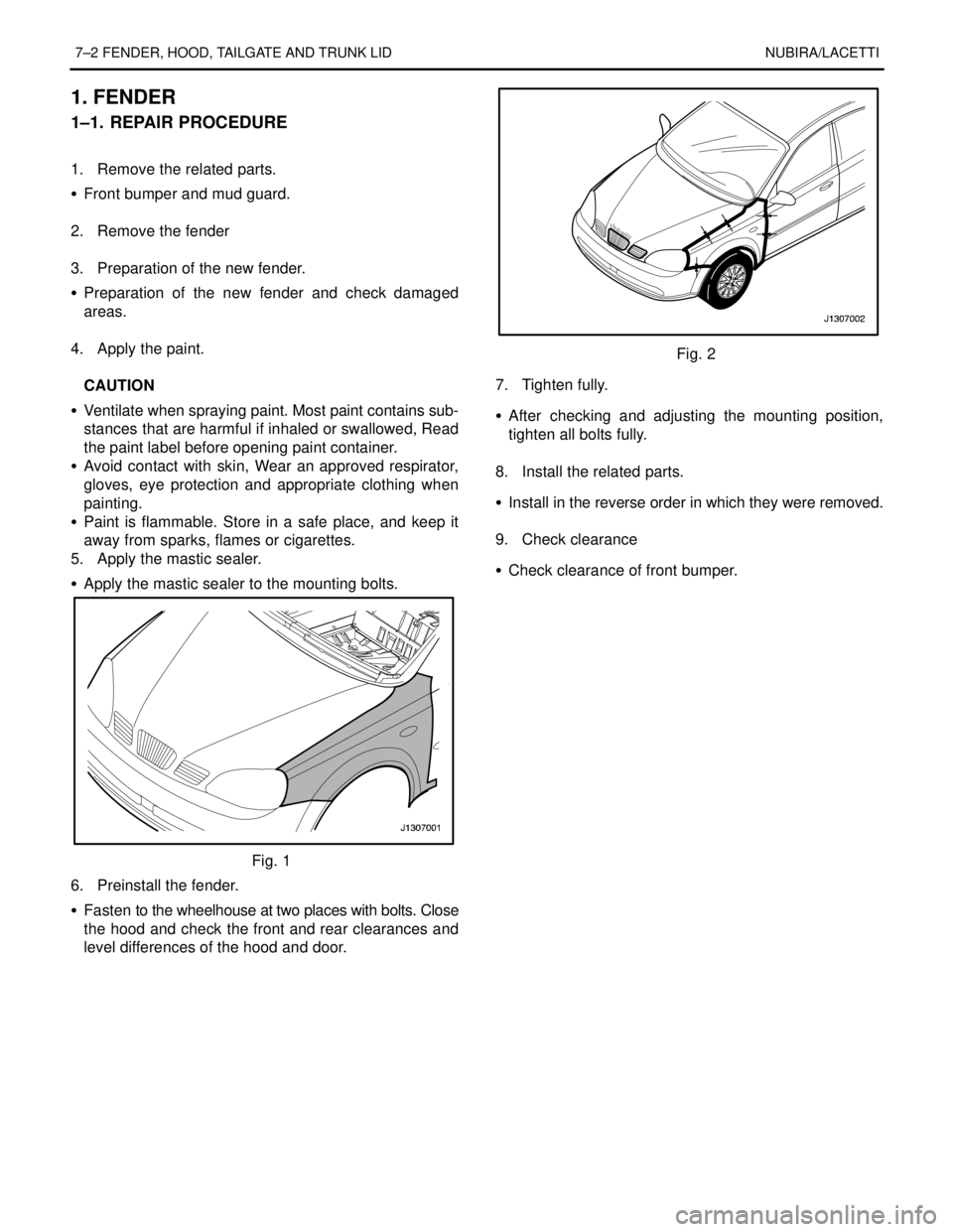
1. FENDER
1–1. REPAIR PROCEDURE
1. Remove the related parts.
S Front bumper and mud guard.
.
2. Remove the fender
.
3. Preparation of the new fender.
S Preparation of the new fender and check damaged
areas.
.
4. Apply the paint.
.
CAUTION
S Ventilate when spraying paint. Most paint contains sub-
stances that are harmful if inhaled or swallowed, Read
the paint label before opening paint container.
S Avoid contact with skin, Wear an approved respirator,
gloves, eye protection and appropriate clothing when
painting.
S Paint is flammable. Store in a safe place, and keep it
away from sparks, flames or cigarettes.
5. Apply the mastic sealer.
S Apply the mastic sealer to the mounting bolts.
Fig. 1
6. Preinstall the fender.
S Fasten to the wheelhouse at two places with bolts. Close
the hood and check the front and rear clearances and
level differences of the hood and door.
Fig. 2
7. Tighten fully.
S After checking and adjusting the mounting position,
tighten all bolts fully.
.
8. Install the related parts.
S Install in the reverse order in which they were removed.
.
9. Check clearance
S Check clearance of front bumper.