100 DAEWOO LACETTI 2004 Service Repair Manual
[x] Cancel search | Manufacturer: DAEWOO, Model Year: 2004, Model line: LACETTI, Model: DAEWOO LACETTI 2004Pages: 2643, PDF Size: 80.54 MB
Page 15 of 2643
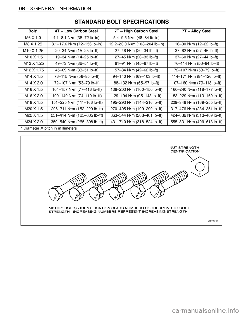
0B – 8IGENERAL INFORMATION
DAEWOO V–121 BL4
STANDARD BOLT SPECIFICATIONS
Bolt*4T – Low Carbon Steel7T – High Carbon Steel7T – Alloy Steel
M6 X 1.04.1–8.1 NSm (36–72 lb–in)5.4–9.5 NSm (48–84 lb–in)–
M8 X 1.25 8.1–17.6 NSm (72–156 lb–in)12.2–23.0 NSm (108–204 lb–in)16–30 NSm (12–22 lb–ft)
M10 X 1.25 20–34 NSm (15–25 lb–ft)27–46 NSm (20–34 lb–ft)37–62 NSm (27–46 lb–ft)
M10 X 1.5 19–34 NSm (14–25 lb–ft)27–45 NSm (20–33 lb–ft)37–60 NSm (27–44 lb–ft)
M12 X 1.25 49–73 NSm (36–54 lb–ft)61–91 NSm (45–67 lb–ft)76–114 NSm (56–84 lb–ft)
M12 X 1.75 45–69 NSm (33–51 lb–ft)57–84 NSm (42–62 lb–ft)72–107 NSm (53–79 lb–ft)
M14 X 1.5 76–115 NSm (56–85 lb–ft)94–140 NSm (69–103 lb–ft)114–171 NSm (84–126 lb–ft)
M14 X 2.0 72–107 NSm (53–79 lb–ft)88–132 NSm (65–97 lb–ft)107–160 NSm (79–118 lb–ft)
M16 X 1.5 104–157 NSm (77–116 lb–ft)136–203 NSm (100–150 lb–ft)160–240 NSm (118–177 lb–ft)
M16 X 2.0 100–149 NSm (74–110 lb–ft)129–194 NSm (95–143 lb–ft)153–229 NSm (113–169 lb–ft)
M18 X 1.5 151–225 NSm (111–166 lb–ft)195–293 NSm (144–216 lb–ft)229–346 NSm (169–255 lb–ft)
M20 X 1.5 206–311 NSm (152–229 lb–ft)270–405 NSm (199–299 lb–ft)317–476 NSm (234–351 lb–ft)
M22 X 1.5 251–414 NSm (185–305 lb–ft)363–544 NSm (268–401 lb–ft)424–636 NSm (313–469 lb–ft)
M24 X 2.0 359–540 NSm (265–398 lb–ft)431–710 NSm (318–524 lb–ft)555–831 NSm (409–613 lb–ft)
* Diameter X pitch in millimeters
Page 33 of 2643

SECTION : 1A
GENERAL ENGINE INFORMATION
TABLE OF CONTENTS
DIAGNOSIS1A–1 . . . . . . . . . . . . . . . . . . . . . . . . . . . . . . . .
Compression Test 1A–1. . . . . . . . . . . . . . . . . . . . . . . . .
Oil Pressure Test 1A–2. . . . . . . . . . . . . . . . . . . . . . . . . .
Oil Leak Diagnosis 1A–3. . . . . . . . . . . . . . . . . . . . . . . .
Knock Diagnosis 1A–4. . . . . . . . . . . . . . . . . . . . . . . . . . Noise Diagnosis 1A–8. . . . . . . . . . . . . . . . . . . . . . . . . .
GENERAL INFORMATION1A–11 . . . . . . . . . . . . . . . . . .
Cleanliness and Care 1A–11. . . . . . . . . . . . . . . . . . . . .
On–Engine Service 1A–11. . . . . . . . . . . . . . . . . . . . . . .
DIAGNOSIS
COMPRESSION TEST
Important : Disconnect the Crankshaft Position (CKP)
Sensor connector to disable the fuel and the ignition sys-
tems.
Test the compression pressure for each cylinder. Low
compression pressure may be the fault of the valves or the
pistons. The following conditions should be considered
when you check the cylinder compression:
S The engine should be at normal operating tempera-
ture.
S The throttle must be wide open.
S All the spark plugs should be removed.
S The battery must be at or near full charge.
1. Place approximately three squirts of oil from a
plunger– type oiler into each spark plug port.
2. Insert the engine compression gauge into each
spark plug port.
3. Crank test each cylinder with four to five compres-
sion strokes using the starter motor.4. The lowest reading should not be less than 70% of
the highest reading. The compression gauge read-
ing should not be less than 689 kPa (100 psi) for
any of the cylinders.
5. Examine the gauge readings obtained after the four
”puffs” per cylinder are obtained from cranking the
starter motor. The readings are explained in the
following descriptions:
S Normal Condition – Compression builds up quickly
and evenly to the specified compression on each
cylinder.
S Piston Rings Faulty – Compression is low on the
first stroke and tends to build up on following
strokes, but the compression pressure does not
reach normal. The compression pressure improves
considerably with the addition of oil into the cylin-
der.
S Valves Faulty – Low compression pressure on the
first stroke. The compression pressure does not
tend to build up on the following strokes. The com-
pression pressure does not improve much with the
addition of oil into the cylinder.
Page 46 of 2643

1.4L/1.6L DOHC ENGINE MECHANICAL 1C1 – 3
DAEWOO V–121 BL4
ApplicationDescription (Manual and Automatic)
1.4L DOHC1.6L DOHC
Crankshaft:
Main Journal:
Diameter (All)
Taper (Maximum)
Out of Round (Maximum)55 mm (2.71 in.)
0.005 mm (0.0001 in.)
0.004 mm (0.0001 in.)54.982–54.994 mm
(2.164–2.165 in.)
0.005 mm (0.0001 in.)
0.004 mm (0.0001 in.)
Main Bearing Clearance (All)0.026–0.042 mm (0.001–0.002 in.)0.026–0.042 mm (0.001–0.002 in.)
Crankshaft End Play0.1 mm (0.003 in.)0.05–0.28 mm (0.002–0.011 in.)
Connecting Rod Journal:
Diameter (All)43 mm (1.69 in.)
42.971–42.987 mm
(1.691–1.692 in.)
Taper (Maximum)0.005 mm (0.0001 in.)0.005 mm (0.0001 in.)
Out of Round (Maximum)0.004 mm (0.0001 in.)0.004 mm (0.0001 in.)
Rod Bearing Clearance (All)0.019–0.070 mm
(0.0007–0.0028 in.)0.019–0.071 mm
(0.0007–0.0028 in.)
Rod Side Clearance0.070–0.242 mm
(0.0027–0.009 in.)0.070–0.242 mm
(0.0027–0.009 in.)
Valve System:
Valve Lash CompensatorsHydraulicHydraulic
Face Angle (All)45°~45.25°90°~90.5°
Seat Angle (All)44.5°~45°89°~90°
Seat Runout (Maximum, All)0.05 mm (0.002 in.)0.05 mm (0.002 in.)
Face Runout (Maximum, All)0.03 mm (0.0012 in.)0.03 mm (0.0012 in.)
Seat Width:
Intake
Exhaust1.17–1.57 mm (0.046–0.062 in.)
1.4–1.8 mm (0.055–0.071 in.)1.17–1.57 mm (0.046–0.062 in.)
1.4–1.8 mm (0.055–0.071 in.)
Valve Guide Inside Diameter (All)6.00–6.02 mm (0.236–0.237 in.)6.00–6.02 mm (0.236–0.237 in.)
Valve Stem Diameter (All)6 mm (0.236 in.)6 mm (0.236 in.)
Valve Diameter (All):
Intake
Exhaust28.57 mm (1.125 in.)
27.24 mm (1.074 in.)28.6 mm (1.126 in.)
27.2 mm (1.072 in.)
Valve Spring Loads:
Valve Open
Valve Closed580 ± 29N (426 ± 21 lbs)
260 ± 13N (191 ± 9.6 lbs)580–26N (428–19 lbs)
@23.0 mm(0.90 in.)
260”13N(192” 9 lbs) @
32.0mm(1.25 in.)
Valve Spring Free Length41.2 mm (1.622 in.)41.2 mm (1.622 in.)
Oil Pump:
Gap Between Oil Pump Body and Out
Rotor0.400~0.484 mm
(0.0157~0.019 in.)0.400~0.484 mm (0.0157~0.019 in.)
Out Rotor Side Clearance0.045~0.100 mm
(0.0018~0.0039 in.)0.045~0.100 mm (0.02~0.004 in.)
Page 122 of 2643

1C2 – 2I1.8L DOHC ENGINE MECHANICAL
DAEWOO V–121 BL4
SPECIFICATIONS
ENGINE SPECIFICATIONS
ApplicationDescription
General Data:
Engine Type1.8L DOHCT18SED
Displacement1.8L DOHC1,799 cm3 (109.7 in3)
Bore Stroke1.8L DOHC81.6 x 86 mm (3.21 in. x 3.38 in.)
Compression Ratio9.6 ± 0.02:1
Firing Oder1–3–4–2
Cylinder Bore:
Diameter1.8L DOHC81.575~81.625 mm (3.2116~3.2135 in.)
Out of Round (Maximum)0.013 mm (0.0005 in.)
Taper (Maximum)0.013 mm (0.0005 in.)
Pistion:
Diameter1.8L DOHC81.575~82.105 mm (3.2115~3.2325 in.)
Clearance to Bore0.0100~0.0300 mm (0.00039~0.00110 in.)
Piston Protrusion0.5 mm (0.019 in.) Maximum
Piston Taper0.013 (0.0005 in.)
Piston Rings:
Ring, End Gap: Top Compression0.3~0.5 mm (0.011~ 0.019 in.)
Ring, End Gap: Second Compression0.3~0.5 mm (0.011~0.019 in.)
Piston Pin:
Diameter20.9970~20.9985 mm (0.82665~0.82671 in.)
Pin Offset0.8 mm (0.03 in.) Towards Thrust Side
Clearance: In Piston0.0035~0.0140 mm (0.00013~0.00055 in.)
Clearance: In RodInterference Fit in Rod
Length61.5 mm (2.42 in.)
Camshaft:
Lift – Intake9.2 mm (0.36 in.)
Lift – Exhaust9.2 mm (0.36 in.)
End Play0.040~0.14 mm (0.0015~0.0055 in.)
Bearing Journal OD42.455~43.470 mm (1.6714~1.7114 in.)
Crankshaft:
Main Journal:
Diameter (All)
Out of Round (Maximum)57.974~57.995 mm (2.2824~2.2832 in.)
0.003 mm (0.0001 in.)
Main Bearing Clearance (All)0.015~0.040 mm (0.00059~0.00157 in.)
Crankshaft End Play0.070~0.302 mm (0.0027~0.0118 in.)
Service OversizeAvailable in 2 sizes
0.25 mm and 0.50 mm (0.0098~0.0196 in.)
Connecting Rod Journal:
Page 247 of 2643

SECTION : 1F
ENGINE CONTROLS
CAUTION : Disconnect the negative battery cable before removing or installing any electrical unit o r w hen a
tool or equipment could easily come in contact with exposed electrical terminals. Disconnecting this cable will
help prevent personal injury and damage to the vehicle. The ignition must also be in LOCK unless otherwise
noted.
TABLE OF CONTENTS
SPECIFICATIONS1F–6 . . . . . . . . . . . . . . . . . . . . . . . . . .
Engine Data Display Tables 1F–6. . . . . . . . . . . . . . . . .
Engine Data Display Table Definitions 1F–7. . . . . . . .
Fastener Tightening Specifications 1F–10. . . . . . . . .
Fuel System Specifications 1F–11. . . . . . . . . . . . . . . . .
Temperature Vs Resistance 1F–11. . . . . . . . . . . . . . . .
SCHEMATIC AND ROUTING DIAGRAMS1F–12 . . . .
ECM Wiring Diagram
(1.4L/1.6L DOHC – 1 OF 6) 1F–12. . . . . . . . . . . . . .
ECM Wiring Diagram
(1.4L/1.6L DOHC – 2 OF 6) 1F–13. . . . . . . . . . . . . .
ECM Wiring Diagram
(1.4L/1.6L DOHC – 3 OF 6) 1F–14. . . . . . . . . . . . . .
ECM Wiring Diagram
(1.4L/1.6L DOHC – 4 OF 6) 1F–15. . . . . . . . . . . . . .
ECM Wiring Diagram
(1.4L/1.6L DOHC – 5 OF 6) 1F–16. . . . . . . . . . . . . .
ECM Wiring Diagram
(1.4L/1.6L DOHC – 6 OF 6) 1F–17. . . . . . . . . . . . . .
ECM Wiring Diagram (1.8L DOHC – 1 OF 6) 1F–18.
ECM Wiring Diagram (1.8L DOHC – 2 OF 6) 1F–19.
ECM Wiring Diagram (1.8L DOHC – 3 OF 6) 1F–20.
ECM Wiring Diagram (1.8L DOHC – 4 OF 6) 1F–21.
ECM Wiring Diagram (1.8L DOHC – 5 OF 6) 1F–22.
ECM Wiring Diagram (1.8L DOHC – 6 OF 6) 1F–23.
Connector End View 1F–24. . . . . . . . . . . . . . . . . . . . . .
COMPONENT LOCATOR1F–28 . . . . . . . . . . . . . . . . . . .
Component Locator (1.4L/1.6L DOHC) 1F–28. . . . . .
Component Locator (1.8L DOHC) 1F–29. . . . . . . . . . .
DIAGNOSIS1F–30 . . . . . . . . . . . . . . . . . . . . . . . . . . . . . . .
SYSTEM DIAGNOSIS 1F–30. . . . . . . . . . . . . . . . . . . . . .
Diagnostic Aids 1F–30. . . . . . . . . . . . . . . . . . . . . . . . . . .
Idle Learn Procedure 1F–30. . . . . . . . . . . . . . . . . . . . . .
TEC (Tooth Error Correction) Learn Procedure 1F–31ON–Board Diagnostic (EOBD) System Check
(1.4L/1.6L DOHC) 1F–32. . . . . . . . . . . . . . . . . . . . . . .
ON–Board Diagnostic (EOBD) System Check
(1.8L DOHC) 1F–34. . . . . . . . . . . . . . . . . . . . . . . . . . .
Multiple ECM Informationn Sensor Dtcs Set 1F–36. .
Engine Cranks But Will Not Run
(1.4L/1.6L DOHC) 1F–40. . . . . . . . . . . . . . . . . . . . . . .
Engine Cranks But Will Not Run (1.8L DOHC) 1F–47
No Malfunction Indicator Lamp (
1.4L/1.6L DOHC) 1F–54. . . . . . . . . . . . . . . . . . . . . . .
No Malfunction Indicator Lamp (1.8L DOHC) 1F–56.
Malfunction Indicator Lamp On Steady (1.4L/1.6L
DOHC) 1F–58. . . . . . . . . . . . . . . . . . . . . . . . . . . . . . . .
Malfunction Indicator Lamp On Steady
(1.8L DOHC) 1F–60. . . . . . . . . . . . . . . . . . . . . . . . . . .
Fuel System Diagnosis 1F–62. . . . . . . . . . . . . . . . . . . .
Fuel Pump Relay Circuit Check
(1.4L/1.6L DOHC) 1F–65. . . . . . . . . . . . . . . . . . . . . . .
Fuel Pump Relay Circuit Check (1.8L DOHC) 1F–68.
Main Relay Circuit Check (1.4L/1.6L DOHC) 1F–71.
Main Relay Circuit Check (1.8L DOHC) 1F–73. . . . . .
Manifold Absolute Pressure Check
(1.4L/1.6L DOHC) 1F–75. . . . . . . . . . . . . . . . . . . . . . .
Manifold Absolute Pressure Check
(1.8L DOHC) 1F–77. . . . . . . . . . . . . . . . . . . . . . . . . . .
Idle Air Control System Check
(1.4L/1.6L DOHC) 1F–79. . . . . . . . . . . . . . . . . . . . . . .
Idle Air Control System Check (1.8L DOHC) 1F–82. .
Ignition System Check (1.4L/1.6L DOHC) 1F–85. . . .
Ignition System Check (1.8L DOHC) 1F–88. . . . . . . .
Engine Cooling Fan Circuit Check – Dual Fan
(1.4L/1.6L DOHC) 1F–93. . . . . . . . . . . . . . . . . . . . . . .
Engine Cooling Fan Circuit Check – Dual Fan
(1.8L DOHC) 1F–100. . . . . . . . . . . . . . . . . . . . . . . . . .
Data Link Connector Diagnosis
(1.4L/1.6L DOHC) 1F–106. . . . . . . . . . . . . . . . . . . . . .
Data Link Connector Diagnosis (1.8L DOHC) 1F–108
Fuel Injector Balance Test 1F–110. . . . . . . . . . . . . . . .
Page 252 of 2643

1F – 6IENGINE CONTROLS
DAEWOO V–121 BL4
SPECIFICATIONS
ENGINE DATA DISPLAY TABLES
Engine Data Display
Parameter
ScalingValue
Desired Idle SpeedRPMECM idle command (varies with temperature)
Engine RPMRPM± 50 RPM from desired RPM in drive (A/T) ± 50 RPM
from desired RPM in neutral (M/T)
MAPkPa29 – 55 (varies with manifold and barometric pressure)
Throttle Position VoltV0 v
Start–up IAT°Cvaries
Intake Air Temperature°C10 – 90 °C
Coolant Temperature (Start–up)°Cvaries
Engine Coolant Temperature°C85 – 105 °C
IAC Motor Position–1 – 50
O2 Sensor (B1–S1)mV1–1000 mV (varies continuously)
O2 Sensor (B1–S2)mV1–1000 mV (varies continuously)
Fuel System StatusClosed Loop/Open
Loop”Closed Loop” (may enter ”Open Loop” at extended idle)
Rich/Lean (B1–S1)Rich/Leanvaries
Lean to Rich AveragemS10 –211 ms or 0 ms
Rich to Lean AveragemS10 –211 ms or 0 ms
Engine Load Value%0 – 100 % (varies)
Short Term Fuel Trim%–30 – 30%
Long Term Fuel Trim%–30 – 30%
Linear EGR FeedbackVvaries
EGR Duty Cycle%0 %
EGR EWMA Result–< = 0
Spark Advance°varies
MIL OdometerKm0 Km
MIL On TimeMin0 Min
Base Injection PWMmS1.0 – 5.0 ms
Barometric PressurekPavaries with altitude
Ignition VoltageV13.5 – 14.8 V
Air/Fuel RatioRatio14.6 (Closed Loop Enable)
Calculated Air FlowG/Svaries
Total Misfire (Current)–0
Misfire History Cyl. 1–0
Misfire History Cyl. 2–0
Misfire History Cyl. 3–0
Misfire History Cyl. 4–0
Vehicle SpeedKm/H0 Km/H
A/C PressureVvaries
Page 254 of 2643

1F – 8IENGINE CONTROLS
DAEWOO V–121 BL4
EGR Desired Position
The desired exhaust gas recirculation (EGR) position is
the commanded EGR position. The ECM calculates the
desired EGR position. The higher the percentage, the lon-
ger the ECM is commanding the EGR valve ON.
Engine Load
Indicates engine load based on manifold absolute pres-
sure. The higher the percentage, the more load the engine
is under.
Engine Run Time
The engine run time is a measure of how long the engine
has been running. When the engine stops running, the tim-
er resets to zero.
Engine Speed
Engine Speed is computed by the ECM from the fuel con-
trol reference input. It should remain close to desired idle
under the various engine loads with the engine idling.
Fan
The Fan Control (FC) Relay is commanded by the ECM.
The FC Relay displays the command as ON or OFF.
Fuel Level Sensor
The Fuel Level Sensor monitors the fuel level in the tank.
The Fuel Level Sensor monitors the rate of change of the
air pressure in the EVAP system. Several of the Enhanced
EVAP System diagnostics are dependent upon the correct
fuel level.
Fuel System Status
The Closed Loop is displayed indicating that the ECM is
controlling the fuel delivery according to the Front Heated
Oxygen Sensor (HO2S1) voltage as close to an air/fuel ra-
tio of 14.7 to 1 as possible.
IAC Position
The scan tool displays the ECM command for the Idle Air
Control (IAC) pintle position in counts. The higher the
number of counts, the greater the commanded idle speed
reads. The Idle Air Control responds to changes in the en-
gine load in order to maintain the desired idle rpm.
Ignition 1 (Voltage)
The ignition volts represent the system voltage measured
by the ECM at the ignition feed circuit.
Intake Air Temperature
The ECM converts the resistance of the Intake Air Tem-
perature (IAT) sensor to degrees in the same manner as
the engine coolant temperature (ECT) sensor. In take air
temperature is used by the ECM to adjust fuel delivery and
spark timing according to incoming air density.Knock Present
The KS Noise Channel indicates when the ECM detects
the KS signal. The ECM should display NO at idle.
Long Term FT
The Long Term Fuel Trim (FT) is derived from the short
term fuel trim value. The Long Term FT is used for the long
term correction of the fuel delivery. A value of 128 counts
(0%) indicates that the fuel delivery requires no com-
pensation in order to maintain a 14.7:1 air to fuel ratio. A
value below 128 counts means that the fuel system is too
rich and the fuel delivery is being reduced. The ECM is de-
creasing the injector pulse width. A value above 128
counts indicates that a lean condition exists for which the
ECM is compensating.
MAP
The Manifold Absolute Pressure (MAP) sensor measures
the change in the intake manifold pressure which results
from engine load and speed changes. As the intake man-
ifold pressure increases, the air density in the intake also
increases and the additional fuel is required.
Misfire History #1–4
Indicates the number of misfires that have occurred after
195 current misfires have been counted. The current mis-
fire counter will add its misfires to the history misfire count-
er after 195 total misfires have taken place. If 1 cylinder is
misfiring, the misfiring current counter will have 195 mis-
fires counted before adding to its history counter. If 2 cylin-
ders are misfiring, the misfiring current counter will add to
their history counters after 97 misfires. The counter incre-
ments only after a misfire diagnostic trouble code (DTC)
has been set.
Front Heated Oxygen Sensor
The pre–converter Front Heated Oxygen Sensor
(HO2S1) reading represents the exhaust oxygen sensor
output voltage. This voltage will fluctuate constantly be-
tween 100 mv (lean exhaust) and 900 mv (rich exhaust)
when the system is operating in a Closed Loop.
Rear Heated Oxygen Sensor
The post–converter Rear Heated Oxygen Sensor
(HO2S2) represents the exhaust oxygen output voltage
past the catalytic converter. This voltage remains inactive,
or the voltage will appear lazy within a range of 100 mv
(lean exhaust) and 900 mv (rich exhaust) when operating
in a Closed Loop.
Short Term FT
The Short Term FT represents a short term correction to
fuel delivery by the ECM in response to the amount of time
the oxygen sensor voltage spends above or below the 450
mv threshold. If the oxygen sensor has mainly been below
450 mv, indicating a lean air/fuel mixture, short term fuel
trim will increase to tell the ECM to add fuel. If the oxygen
sensor voltage stays mainly above the threshold, the ECM
will reduce fuel delivery to compensate for the indicated
rich condition.
Page 255 of 2643

ENGINE CONTROLS 1F – 9
DAEWOO V–121 BL4
Spark Advance
This is a display of the spark advance Ignition Coil (IC) cal-
culation which the ECM is programming in the ignition sys-
tem. It computes the desired spark advance using data
such as engine temperature, rpm, engine load, vehicle
speed and operating mode.
TCC Engaged
When the brake pedal is applied, the Torque Converter
Clutch (TCC) brake switch sends a signal to the ECM to
disengage the TCC and disable the cruise control.
Total Misfire Current Counter
Indicates the total number of misfires that have been de-tected in all the cylinders after 100 engine cycles. One
cycle equals one complete 4 stroke cycle. The total misfire
only increments during the steady state cruise conditions.
TP Sensor
The ECM uses the TP Sensor in order to determine the
amount of the throttle demanded by the vehicle’s operator.
The TP Sensor reads between 0.36–0.96 volts at idle to
above 4 volts at WOT.
Vehicle Speed
The vehicle speed sensor signal is converted into mph or
km/h for display. The vehicle speed output from the ECM
is 4000 pulses per mile. The scan tool uses the KWP 2000
serial data from the ECM to obtain vehicle speed, while the
Instrument Panel Cluster (IPC), cruise control module and
the chime alarm module use the 4000 ppm output.
Page 257 of 2643

ENGINE CONTROLS 1F – 11
DAEWOO V–121 BL4
FUEL SYSTEM SPECIFICATIONS
Gasoline
All engines are designed to use unleaded fuel only. Un-
leaded fuel must be used for proper emission control sys-
tem operation. Its use will also minimize spark plug fouling
and extend engine oil life. Using leaded fuel can damage
the emission warranty coverage. The fuel should meet
specification ASTM D4814 for the U.S. or CGSB 3.5 M93
for Canada. All engines are designed to use unleaded fuel
with a minimum U(R+M)/2e (pump) octane number of 87,
where R=research octane number, and M=motor octane
number.
Ethanol
You may use fuel containing ethanol (ethyl alcohol) orgrain alcohol providing that there is no more than 10 per-
cent ethyl alcohol by volume.
Methanol
Do not use fuels containing methanol. Methanol can cor-
rode metal parts and cause damage to plastic and rubber
parts in the fuel system.
Methyl Tertiary–Butyl Ether (MTBE)
You may use fuel containing Methyl Tertiary–Butyl Ether
(MTBE) providing there is no more than 15 percent MTBE
by volume.
TEMPERATURE VS RESISTANCE
°C°FECT SensorIAT Sensor
OHMS
Temperature vs Resistance Values (Approximate)
100212177187
90194241246
80176332327
70158467441
60140667603
50122973837
4511 31188991
4010414591180
359518021412
308622381700
257727962055
206835202500
155944503055
105056703760
54172804651
03294205800
–523123007273
–1014161809200
–155214509200
–20–42868015080
–30–225270025600
–40–4010070045300
Page 286 of 2643

1F – 40IENGINE CONTROLS
DAEWOO V–121 BL4
ENGINE CRANKS BUT WILL NOT RUN (1.4L/1.6L DOHC)
Test Description
The number(s) below refer to step(s) on the diagnostic
table.
1. The On–Board Diagnostic (EOBD) System Check
prompts the technician to complete some basic
checks and store the freeze frame and failure re-
cords data on the scan tool if applicable. This
creates an electronic copy of the data taken when
the occurred. The information is then stored on the
scan tool for later reference.
2. By performing a compression test, it can be deter-
mined if the engine has the mechanical ability to
run.
3. It is important to check for the presence of sparkfrom all of the ignition wires. If spark is present from
one to three of the ignition coil terminals, the Crank-
shaft Position (CKP) sensor is OK.
19. In checking the engine control module (ECM) out-
puts for the electronic spark timing signal, it recom-
mended to use an oscilloscope to view the varying
voltage signals. In measuring these outputs with a
voltmeter, intermittent errors may occur that cannot
be seen by a voltmeter.
35. This step checks for proper operation of the ECM’s
control of the fuel pump circuit.
59. This step checks for a ground signal being supplied
by the ECM to operate the fuel injectors. If there is
no ground present during the cranking of the en-
gine, and the fuel injector wiring is OK, the ECM is
at fault.
Engine Cranks But Will Not Run (1.4L/1.6L DOHC)
CAUTION : Use only electrically insulated pliers when
handling ignition wires with the engine running to
prevent an electrical shock.
CAUTION : Do not pinch or restrict nylon fuel lines.Damage to the lines could cause a fuel leak, resulting
in possible fire or personal injury.
Step
ActionValue(s)YesNo
1Perform an Euro On–Board Diagnostic (EOBD)
System Check.
Is the check complete.–Go to Step 2Go to
”Euro On–
Board Diagnos-
tic System
Check”
2Crank the engine.
Does the engine start and continue to run?–System OKGo to Step 3
3Perform a cylinder compression test.
Is the cylinder compression for all of the cylinders at
or above the value specified?689 kPa
(100 psi)Go to Step 7Go to Step 4
4Inspect the timing belt alignment.
Is the timing belt in alignment?–Go to Step 6Go to Step 5
5Align or replace the timing belt as needed.
Is the repair complete?–Go to Step 2–
6Repair internal engine damage as needed.
Is the repair complete?–Go to Step 2–
7Inspect the fuel pump fuse.
Is the problem found?–Go to Step 8Go to Step 9
8Replace the fuse.
Is the repair complete?–Go to Step 2–
9Check for the presence of spark from all of the igni-
tion wires while cranking the engine.
Is spark present from all of the ignition wires?–Go to Step 23Go to Step 10
101. Measure the resistance of the ignition wires.
2. Replace any of the ignition wire(s) with a resist-
ance above the value specified.
3. Check for the presence of spark from all of the
ignition wire.
Is spark present from all of the ignition wires?30000 WGo to Step 2Go to Step 11