ECM DAEWOO LACETTI 2004 Service Repair Manual
[x] Cancel search | Manufacturer: DAEWOO, Model Year: 2004, Model line: LACETTI, Model: DAEWOO LACETTI 2004Pages: 2643, PDF Size: 80.54 MB
Page 64 of 2643
1.4L/1.6L DOHC ENGINE MECHANICAL 1C1 – 21
DAEWOO V–121 BL4
Installation Procedure
1. Install the exhaust manifold and gasket.
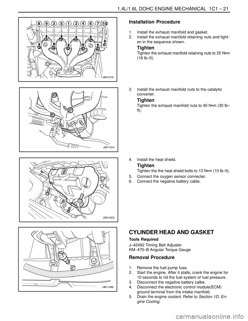
2. Install the exhaust manifold retaining nuts and tight-
en in the sequence shown.
Tighten
Tighten the exhaust manifold retaining nuts to 25 NSm
(18 lb–ft).
3. Install the exhaust manifold nuts to the catalytic
converter.
Tighten
Tighten the exhaust manifold nuts to 40 NSm (30 lb–
ft).
4. Install the heat shield.
Tighten
Tighten the the heat shield bolts to 13 NSm (10 lb–ft).
5. Connect the oxygen sensor connecter.
6. Connect the negative battery cable.
CYLINDER HEAD AND GASKET
Tools Required
J–42492 Timing Belt Adjuster
KM–470–B Angular Torque Gauge
Removal Procedure
1. Remove the fuel pump fuse.
2. Start the engine. After it stalls, crank the engine for
10 seconds to rid the fuel system of fuel pressure.
3. Disconnect the negative battery calbe.
4. Disconnect the electronic control module(ECM)
ground terminal from the intake manifold.
5. Drain the engine coolant. Refer to Section 1D, En-
gine Cooling.
Page 72 of 2643
1.4L/1.6L DOHC ENGINE MECHANICAL 1C1 – 29
DAEWOO V–121 BL4
38. Connect the DIS coil connector.
39. Connect the fuel injector harness connectors.
40. Connect the oxygen sensor connector and the
ECM ground terminal at the intake manifold.
41. Install the fuel pump fuse.
42. Connect the negative battery ground cable.
43. Refill the engine cooling system. Refer to Sec-
tion1D, Engine Cooling.
CAMSHAFTS
Removal Procedure
1. Remove the camshaft cover. Refer to ”Camshaft
Cover” in this section.
2. Remove the timing belt. Refer to ”Timing Belt” in
this section.
Notice : Take extreme care to prevent any scratches,
nicks or damage to the camshafts.
3. While holding the intake camshaft firmly in place,
remove the intake camshaft gear bolt and gear.
4. While holding the exhaust camshaft firmly in place,
remove the exhaust camshaft gear bolt and gear.
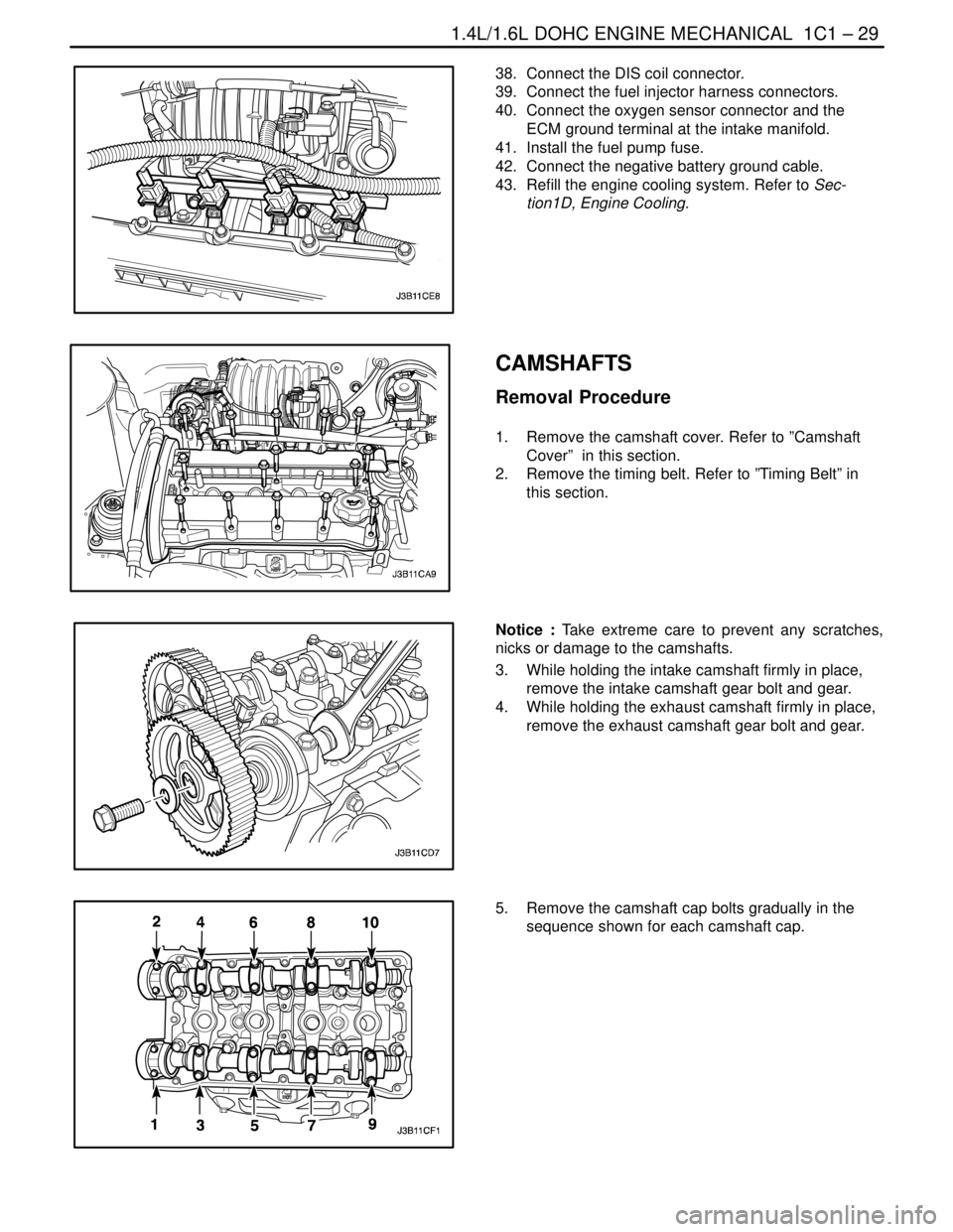
5. Remove the camshaft cap bolts gradually in the
sequence shown for each camshaft cap.
Page 91 of 2643
1C1 – 48I1.4L/1.6L DOHC ENGINE MECHANICAL
DAEWOO V–121 BL4
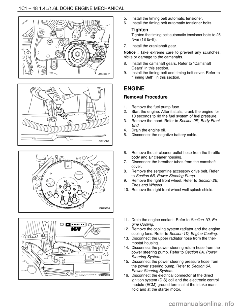
5. Install the timing belt automatic tensioner.
6. Install the timing belt automatic tensioner bolts.
Tighten
Tighten the timing belt automatic tensioner bolts to 25
NSm (18 lb–ft).
7. Install the crankshaft gear.
Notice : Take extreme care to prevent any scratches,
nicks or damage to the camshafts.
8. Install the camshaft gears. Refer to ”Camshaft
Gears” in this section.
9. Install the timing belt and timing belt cover. Refer to
”Timing Belt” in this section.
ENGINE
Removal Procedure
1. Remove the fuel pump fuse.
2. Start the engine. After it stalls, crank the engine for
10 seconds to rid the fuel system of fuel pressure.
3. Remove the hood. Refer to Section 9R, Body Front
End.
4. Drain the engine oil.
5. Disconnect the negative battery cable.
6. Remove the air cleaner outlet hose from the throttle
body and air cleaner housing.
7. Disconnect the breather tubes from the camshaft
cover.
8. Remove the serpentine accessory drive belt. Refer
to Section 6B, Power Steering Pump.
9. Remove the right front wheel. Refer to Section 2E,
Tires and Wheels.
10. Remove the right front wheel well splash shield.
11. Drain the engine coolant. Refer to Section 1D, En-
gine Cooling.
12. Remove the cooling system radiator and the engine
cooling fans. Refer to Section 1D, Engine Cooling.
13. Disconnect the upper radiator hose from the ther-
mostat housing.
14. Disconnect the power steering return hose from the
power steering pump. Refer to Section 6A, Power
Steering System.
15. Disconnect the power steering pressure hose from
the power steering pump. Refer to Section 6A,
Power Steering System.
16. Disconnect the electrical connector at the direct
ignition system (DIS) coil and the electronic control
module (ECM) ground terminal at the intake man-
ifold and at the starter motor.
Page 95 of 2643
1C1 – 52I1.4L/1.6L DOHC ENGINE MECHANICAL
DAEWOO V–121 BL4
18. Connect the power steering pressure hose.
19. Connect the power steering return hose.
20. Install the A/C compressor, if equipped. Refer to
Section 7B, Manual Control Heating, Ventilation,
and Air Conditioning Systems.
21. Install the generator. Refer to Section 1E, Engine
Electrical.
22. Install the serpentine accessory drive belt. Refer to
Section 6B, Power Steering Pump.
23. Install the right front wheel well splash shield.
24. Install the right front wheel. Refer to Section 2E,
Tires and Wheels.
25. Connect the fuel feed line to the fuel rail.
26. Connect all of the necessary vacuum lines, includ-
ing the brake booster vacuum hose.
27. Connect the O2 sensor connector, if equipped.
28. Connect the starter solenoid ”S” terminal wire and
power lead.
29. Connect the generator voltage regulator connector
and power lead.
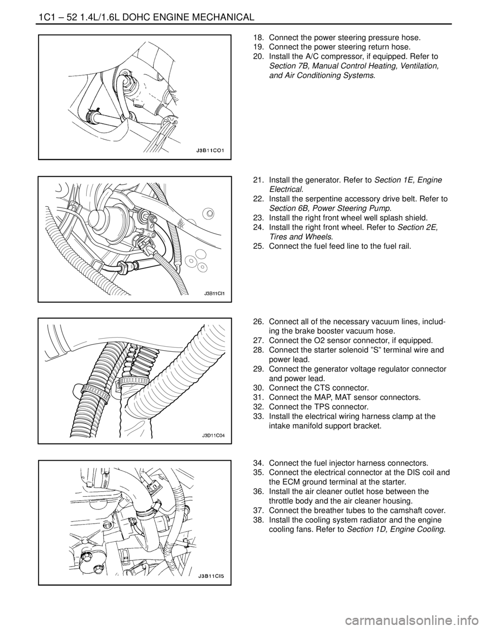
30. Connect the CTS connector.
31. Connect the MAP, MAT sensor connectors.
32. Connect the TPS connector.
33. Install the electrical wiring harness clamp at the
intake manifold support bracket.
34. Connect the fuel injector harness connectors.
35. Connect the electrical connector at the DIS coil and
the ECM ground terminal at the starter.
36. Install the air cleaner outlet hose between the
throttle body and the air cleaner housing.
37. Connect the breather tubes to the camshaft cover.
38. Install the cooling system radiator and the engine
cooling fans. Refer to Section 1D, Engine Cooling.
Page 133 of 2643
1.8L DOHC ENGINE MECHANICAL 1C2 – 13
DAEWOO V–121 BL4
Installation Procedure
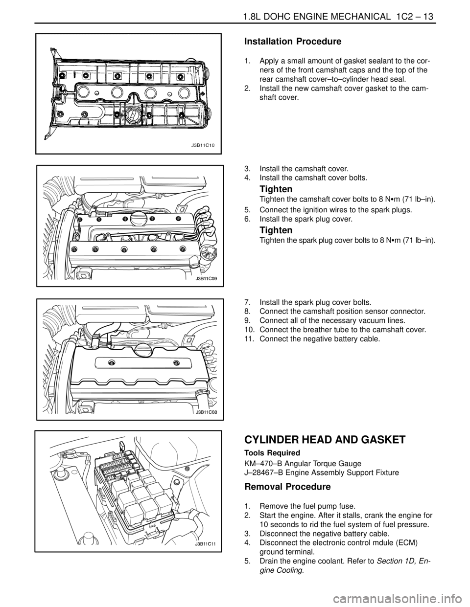
1. Apply a small amount of gasket sealant to the cor-
ners of the front camshaft caps and the top of the
rear camshaft cover–to–cylinder head seal.
2. Install the new camshaft cover gasket to the cam-
shaft cover.
3. Install the camshaft cover.
4. Install the camshaft cover bolts.
Tighten
Tighten the camshaft cover bolts to 8 NSm (71 lb–in).
5. Connect the ignition wires to the spark plugs.
6. Install the spark plug cover.
Tighten
Tighten the spark plug cover bolts to 8 NSm (71 lb–in).
7. Install the spark plug cover bolts.
8. Connect the camshaft position sensor connector.
9. Connect all of the necessary vacuum lines.
10. Connect the breather tube to the camshaft cover.
11. Connect the negative battery cable.
CYLINDER HEAD AND GASKET
Tools Required
KM–470–B Angular Torque Gauge
J–28467–B Engine Assembly Support Fixture
Removal Procedure
1. Remove the fuel pump fuse.
2. Start the engine. After it stalls, crank the engine for
10 seconds to rid the fuel system of fuel pressure.
3. Disconnect the negative battery cable.
4. Disconnect the electronic control mdule (ECM)
ground terminal.
5. Drain the engine coolant. Refer to Section 1D, En-
gine Cooling.
Page 142 of 2643
1C2 – 22I1.8L DOHC ENGINE MECHANICAL
DAEWOO V–121 BL4
56. Connect the CTS connector.
57. Connect the engine CTS connector.
58. Connect the IAC valve connector.
59. Connect the TPS connector.
60. Install the CCP and the EGR solenoid bracket bolt.
Tighten
Tighten the charcoal canister purge and exhaust gas
recirculation solenoid bracket bolt to 5 NSm (44 lb–in).
61. Connect the DIS coil connector.
62. Connect the O2 sensor connector, if equipped.
63. Connect the ECM ground terminal.
64. Install the fuel pump fuse.
65. Connect the negative battery ground cable.
66. Refill the engine cooling system. Refer to Section
1D, Engine Cooling.
CAMSHAFTS
Removal Procedure
1. Remove the timing belt. Refer to ”Timing Belt” in
this section.
2. Disconnect the breather tube at the camshaft cov-
er.
3. Disconnect the engine ventilation hose at the cam-
shaft cover.
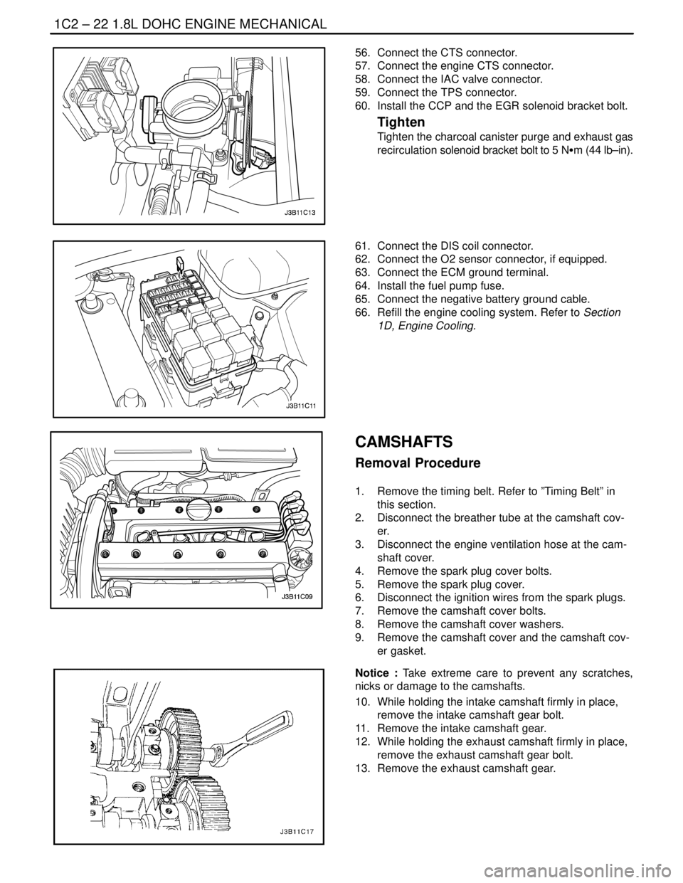
4. Remove the spark plug cover bolts.
5. Remove the spark plug cover.
6. Disconnect the ignition wires from the spark plugs.
7. Remove the camshaft cover bolts.
8. Remove the camshaft cover washers.
9. Remove the camshaft cover and the camshaft cov-
er gasket.
Notice : Take extreme care to prevent any scratches,
nicks or damage to the camshafts.
10. While holding the intake camshaft firmly in place,
remove the intake camshaft gear bolt.
11. Remove the intake camshaft gear.
12. While holding the exhaust camshaft firmly in place,
remove the exhaust camshaft gear bolt.
13. Remove the exhaust camshaft gear.
Page 166 of 2643
1C2 – 46I1.8L DOHC ENGINE MECHANICAL
DAEWOO V–121 BL4
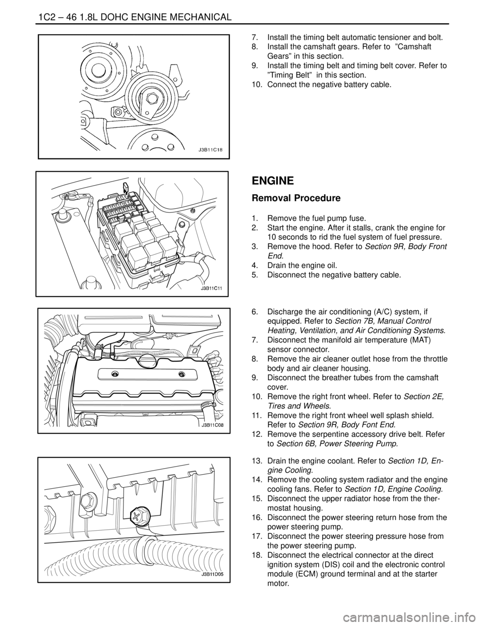
7. Install the timing belt automatic tensioner and bolt.
8. Install the camshaft gears. Refer to ”Camshaft
Gears” in this section.
9. Install the timing belt and timing belt cover. Refer to
”Timing Belt” in this section.
10. Connect the negative battery cable.
ENGINE
Removal Procedure
1. Remove the fuel pump fuse.
2. Start the engine. After it stalls, crank the engine for
10 seconds to rid the fuel system of fuel pressure.
3. Remove the hood. Refer to Section 9R, Body Front
End.
4. Drain the engine oil.
5. Disconnect the negative battery cable.
6. Discharge the air conditioning (A/C) system, if
equipped. Refer to Section 7B, Manual Control
Heating, Ventilation, and Air Conditioning Systems.
7. Disconnect the manifold air temperature (MAT)
sensor connector.
8. Remove the air cleaner outlet hose from the throttle
body and air cleaner housing.
9. Disconnect the breather tubes from the camshaft
cover.
10. Remove the right front wheel. Refer to Section 2E,
Tires and Wheels.
11. Remove the right front wheel well splash shield.
Refer to Section 9R, Body Font End.
12. Remove the serpentine accessory drive belt. Refer
to Section 6B, Power Steering Pump.
13. Drain the engine coolant. Refer to Section 1D, En-
gine Cooling.
14. Remove the cooling system radiator and the engine
cooling fans. Refer to Section 1D, Engine Cooling.
15. Disconnect the upper radiator hose from the ther-
mostat housing.
16. Disconnect the power steering return hose from the
power steering pump.
17. Disconnect the power steering pressure hose from
the power steering pump.
18. Disconnect the electrical connector at the direct
ignition system (DIS) coil and the electronic control
module (ECM) ground terminal and at the starter
motor.
Page 170 of 2643

1C2 – 50I1.8L DOHC ENGINE MECHANICAL
DAEWOO V–121 BL4
18. Install the exhaust flex pipe retaining nuts to the
catalytic converter or the connecting pipe.
Tighten
Tighten the exhaust flex pipe–to–catalytic converter
or connecting pipe retaining nuts to 35 NSm (26 lb–ft).
19. Connect the power steering pressure hose.
20. Connect the power steering return hose.
21. Install the A/C compressor, if equipped. Refer to
Section 7B, Manual Control Heating, Ventilation,
and Air Conditioning System.
22. Install the serpentine accessory drive belt. Refer to
Section 6B, Power Steering Pump.
23. Install the right front wheel well splash shield.
24. Install the right front wheel. Refer to Section 2E,
Tires and Wheels.
25. Connect the fuel feed line to the fuel rail.
26. Connect the fuel return line to fuel rail.
27. Install the fuel rail and injector channel cover as an
assembly. Refer to Section 1F, Engine Controls.
28. Connect all of the necessary vacuum lines including
the brake booster vacuum hose.
29. Connect the O2 sensor connector, if equipped.
30. Connect the starter solenoid ”S” terminal wire and
power lead.
31. Connect the generator voltage regulator connector.
32. Connect the CTS connector.
33. Connect the engine CTS connector.
34. Connect the TPS connector.
35. Connect the IAC valve connector.
36. Connect the MAP sensor connector.
37. Connect the knock sensor, if necessary
38. Connect the electrical connector at the DIS ignition
coil and the ECM ground terminal and at the starter
motor.
39. Install the air cleaner outlet hose between the
throttle body and the air cleaner housing.
40. Connect the breather tubes to the camshaft cover.
41. Connect the MAT sensor connector.
42. Install the cooling system radiator and the engine
cooling fans. Refer to Section 1D, Engine Cooling.
Page 199 of 2643

1D – 4IENGINE COOLING
DAEWOO V–121 BL4
COOLING SYSTEM DIAGNOSIS
Engine Overheats
ChecksAction
Check for a loss of the coolant.Add the coolant.
Check for a weak coolant solution.Confirm that the coolant solution is a 50/50 mixture of eth-
ylene glycol and water.
Check the front of the radiator for any dirt, any leaves, or
any insects.Clean the front of the radiator.
Check for leakage from the hoses, the coolant pump, the
heater, the thermostat housing, the radiator, the core
plugs, or the head gasket.Replace any damaged components.
Check for a faulty thermostat.Replace a damaged thermostat.
Check for retarded ignition timing.Perform an ECM code diagnosis. Confirm the integrity of
the timing belt.
Check for an improperly operating electric cooling fan.Replace the electric cooling fan.
Check for radiator hoses that are plugged or rotted.Replace any damaged radiator hoses.
Check for a faulty water pump.Replace a faulty water pump.
Check for a faulty surge tank cap.Replace a faulty surge tank cap.
Check for a cylinder head or an engine block that is
cracked or plugged.Repair the damaged cylinder head or the damaged engine
block.
Loss of Coolant
ChecksAction
Check for a leak in the radiator.Replace a damaged radiator.
Check for a leak in the following locations:
S Surge tank.
S Hose.Replace the following parts, as needed:
S Surge tank.
S Hose.
Check for loose or damaged radiator hoses, heater hoses,
and connections.Reseat the hoses.
Replace the hoses or the clamps.
Check for leaks in the coolant pump seal.Replace the coolant pump seal.
Check for leaks in the coolant pump gasket.Replace the coolant pump gasket.
Check for an improper cylinder head torque.Tighten the cylinder head bolts to specifications.
Replace the cylinder head gasket, if needed.
Check for leaks in the following locations:
S Intake manifold.
S Cylinder head gasket.
S Cylinder block plug.
S Heater core.
S Radiator drain plug.Repair or replace any components, as needed, to correct
the leak.
Engine Fails to Reach Normal Operating Temperature or Cool Air
from the Heater
ChecksAction
Check to determine if the thermostat is stuck open or is the
wrong type of thermostat.Install a new thermostat of the correct type and heat range.
Check the coolant level to determine if it is below the MIN
mark on the surge tank.Add sufficient coolant to raise the fluid to the specified
mark on the surge tank.
Page 214 of 2643

ENGINE COOLING 1D – 19
DAEWOO V–121 BL4
ELECTRIC COOLING FAN
CAUTION : Keep hands, tools, and clothing away
from the engine cooling fans to help prevent personal
injury. This fan is electric and can turn ON whether or
not the engine is running.
CAUTION : If a fan blade is bent or damaged in any
way, no attempt should be made to repair or reuse the
damaged part. A bent or damaged fan assembly
should always be replaced with a new one. Failure to
do so can result in personal injury.
The cooling fans are mounted behind the radiator in the
engine compartment. The electric cooling fans increase
the flow of air across the radiator fins and across the con-
denser on air condition (A/C)–equipped vehicles. This
helps to speed cooling when the vehicle is at idle or moving
at low speeds.
1.4L DOHC engine fan size is 340mm (13.4 in.) and
1.6L/1.8L DOHC engine main fan size is 300 mm (11.8
inches) in diameter with five blades to aid the air flow
through the radiator and the condenser. An electric motor
attached to the radiator support drives the fan.
A/C models have two fans – the main fan and the auxiliary
fan. The auxiliary fan is 300 mm (11.8 inches) in diameter.
Non–A/C models have only the main fan.
A/C OFF or Non–A/C Model (1.4L/1.6L)
S The cooling fans are actuated by the electronic
control module (ECM) using a low–speed cooling
fan relay and a high–speed cooling fan relay. On
A/C–equipped vehicles, a series/parallel cooling fan
relay is also used.
S The ECM will turn the cooling fans on at low speed
when the coolant temperature reaches 97.5°C
(207.5°F) and the cooling fans off at 95.25°C
(203.4°F).
A/C OFF or Non–A/C Model (1.8L)
S The cooling fans are actuated by the electronic
control module (ECM) using a low–speed cooling
fan relay and a high–speed cooling fan relay. On
A/C–equipped vehicles, a series/parallel cooling fan
relay is also used.
S The ECM will turn the cooling fans on at low speed
when the coolant temperature reaches 93°C
(199°F) and the cooling fans off at 90°C (194°F).
A/C ON (1.4L/1.6L)
S The ECM will turn the cooling fans on at low speed
when the A/C system is on. The ECM will change
to high speed when the coolant temperature reach-
es 101.25°C (214°F) or the high side A/C pressure
reaches 1859 kPa (270 psi).
S The cooling fans will return to low speed when the
coolant temperature reaches 99°C (210°F) and the
high side A/C pressure reaches 1449 kPa (210 psi).
A/C ON (1.8L)
S The ECM will turn the cooling fans on at low speed
when the A/C system is on. The ECM will change
to high speed when the coolant temperature reach-
es 97°C (207°F) or the high side A/C pressure
reaches 1859 kPa (270 psi).
S The cooling fans will return to low speed when the
coolant temperature reaches 94°C (201°F) and the
high side A/C pressure reaches 1449 kPa (210 psi).
ENGINE BLOCK HEATER
The vehicle is designed to accept an engine block heater
that helps to warm the engine and to improve starting in
cold weather. It also can help to reduce fuel consumption
while a cold engine warms up.
The engine block heater is located under the intake man-
ifold and uses an existing expansion plug for installation.