hood latch DAEWOO LACETTI 2004 Service Repair Manual
[x] Cancel search | Manufacturer: DAEWOO, Model Year: 2004, Model line: LACETTI, Model: DAEWOO LACETTI 2004Pages: 2643, PDF Size: 80.54 MB
Page 18 of 2643

GENERAL INFORMATION 0B – 11
DAEWOO V–121 BL4
Chassis and Body
Maintenance ItemMaintenance Interval
Kilometers or time in months, whichever comes first
x 1,000 km1153045607590105120
x 1,000 miles0.6918273645546372
Months–1224364860728496
Interior air filter (A/C)RRRRRRRR
Exhaust pipes & mountingsIIIIIIII
Brake/Clutch fluid (1) (4)IIRIRIRIR
Front brake pads and discs(3)IIIIIIII
Rear brake pads & discs or drums and
linings (3)IIIIIIII
Parking brakeIIIIIIIII
Brake line and connections (Including
booster)IIIIIIII
Manual Transaxle Oil *(1)IIIIIIII
Automatic transaxle fluid *(1) (5)IIIIIIII
Tighten chassis and underbody bolts
and nutsIIIIIIII
Tire condition and inflation pressureIIIIIIIII
Wheel alignment (2)Inspect when abnormal condition is noted
Steering wheel and linkageIIIIIIII
Power steering fluid & lines* (1)IIIIIIIII
Drive shaft bootsIIIIIIII
Seat belts, buckles and anchorsIIIIIIII
Lubricate locks, hinges and hood
latchIIIIIIII
Chart Symbols:
I – Inspect and if necessary correct, clean, replenish, or adjust.
R – Replace or change:
(1) Refer to Recommended Fluids And Lubricants.
(2) And if necessary, rotate and balance wheels.
(3) More frequent if operated under severe conditions: short distance driving, extensive idling, frequent low–speed oper-
aion in stop and go traffic, or driving in dusty conditions.
(4) Change the brake/clutch fluid every 15,000 km (9,000 miles), if the vehicle is mainly driven under the following severe
conditions: driving in hilly or mountainous terrain, or towing a trailer/caravan frequently.
(5) 1.8 DOHC model (ZF 4HP16 Automatic Transaxle): Change automatic transaxle fluid every 60,000 Km (36,000 miles)
if the vehicle is mainly driven under any of the following severe conditions:
S In heavy city traffic where the outside temperature regularly reaches 32°C (90°F) or higher, or
S In hilly or mountainous terrain, or
S When doing frequent trailer towing, or
S Uses such as taxi, police or delivery service.
Page 20 of 2643

GENERAL INFORMATION 0B – 13
DAEWOO V–121 BL4
EACH TIME THE OIL IS CHANGED
Automatic Transaxle Fluid
Refer to fluid level service procedure of Section 5A, ZF
4HP16 Automatic Transaxle.
Manual Transaxle
Check the fluid level and add fluid as required. Refer to
Section 5B, Five–Speed Manual Transaxle.
Brake System Inspection
This inspection should be done when the wheels are re-
moved for rotation. Inspect the lines and the hoses for
proper hookup, binding, leaks, cracks, chafing, etc. In-
spect the disc brake pads for wear. Inspect the rotors for
surface condition. Also inspect the drum brake linings for
wear and cracks. Inspect other brake parts, including the
drums, the wheels cylinders, the parking brake, etc., at the
same time. Check the parking brake adjustment. Inspect
the brakes more often if habit or conditions result in fre-
quent braking.
Steering, Suspension and Front Drive Axle
Boot And Seal Inspection
Inspect the front and rear suspension and the steering
system for damaged, loose or missing parts, signs of wear
or lack of lubrication. Inspect the power steering lines and
the hoses for proper hookup, binding, leaks, cracks, chaf-
ing, etc. Clean and inspect the drive axle boot and seals
for damage, tears or leakage. Replace the seals if neces-
sary.
Exhaust System Inspection
Inspect the complete system (including the catalytic con-
verter if equipped). Inspect the body near the exhaust sys-
tem. Look for broken, damaged, missing, or out–of–posi-
tion parts as well as open seams, holes, loose
connections, or other conditions which could cause heat
buildup in the floor pan or could let exhaust fumes seep
into the trunk or passenger compartment.
Throttle Linkage Inspection
Inspect the throttle linkage for interference or binding,
damaged, or missing parts. Lubricate all linkage joints and
throttle cable joints, the intermediate throttle shaft bearing,
the return spring at throttle valve assembly, and the accel-
erator pedal sliding face with suitable grease. Check the
throttle cable for free movements.
Engine Drive Belts
Inspect all belts for cracks, fraying, wear and proper ten-
sion. Adjust or replace the belts as needed.
Hood Latch Operation
When opening the hood, note the operation of the secon-
dary latch. It should keep the hood from opening all the
way when the primary latch is released. The hood must
close firmly.
AT LEAST ANNUALLY
Lap and Shoulder Belts Condition and
Operation
Inspect the belt system including: the webbing, the
buckles, the latch plates, the retractor, the guide loops and
the anchors.
Movable Head Restraint Operation
On vehicles with movable head restraints, the restraints
must stay in the desired position.
Spare Tire and Jack Storage
Be alert to rattles in the rear of the vehicle. The spare tire,
all the jacking equipment, and the tools must be securely
stowed at all times. Oil the jack ratchet or the screw mech-
anism after each use.
Key Lock Service
Lubricate the key lock cylinder.
Body Lubrication Service
Lubricate all the body door hinges including the hood, the
fuel door, the rear compartment hinges and the latches,
the glove box and the console doors, and any folding seat
hardware.
Transaxle Neutral Switch Operation on
Automatic Transaxle
CAUTION : Take the following precautions because
the vehicle could move without warning and possibly
cause personal injury or property damage:
S Firmly apply the parking brake and the regular
brakes.
S Do not use the accelerator pedal.
S Be ready to promptly turn off the ignition if the ve-
hicle starts.
On automatic transaxle vehicles, try to start the engine in
each gear. The starter should crank only in P (Park) or N
(Neutral).
Parking Brake and Transaxle P (Park)
Mechanism Operation
CAUTION : In order to reduce the risk of personal in-
jury or property damage, be prepared to apply the reg-
ular brakes promptly if the vehicle begins to move.
Park on a fairly steep hill with enough room for movement
in the downhill direction. To check the parking brake, with
the engine running and the transaxle in N (Neutral), slowly
remove foot pressure from the regular brake pedal (until
only the parking brake is holding the vehicle).
To check the automatic transaxle P (Park) mechanism’s
holding ability, release all brakes after shifting the trans-
axle to P (Park).
Underbody Flushing
Flushing the underbody will remove any corrosive materi-
als used for ice and snow removal and dust control. At
least every spring clean the underbody. First, loosen the
sediment packed in closed areas of the vehicle. Then flush
the underbody with plain water.
Page 21 of 2643

0B – 14IGENERAL INFORMATION
DAEWOO V–121 BL4
Engine Cooling System
Inspect the coolant and freeze protection fluid. If the fluid
is dirty or rusty, drain, flush and refill the engine cooling
system with new coolant. Keep the coolant at the proper
mixture in order to ensure proper freeze protection, corro-sion protection and engine operating temperature. Inspect
the hoses. Replace the cracked, swollen, or deteriorated
hoses. Tighten the clamps. Clean the outside of the radia-
tor and the air conditioning condenser. Wash the filler cap
and the neck. Pressure test the cooling system and the
cap in order to help ensure proper operation.
RECOMMENDED FLUIDS AND LUBRICANTS
UsageCapacityFluid/Lubricant
Engine Oil3.75L (4.0 qt) : 1.4L DOHC
3.75L (4.0 qt) : 1.6L DOHC
4.0L (4.2 qt) : 1.8L DOHCAPI SL (ILSAC GF–III) grade or better
SAE 5W–30, SAE10W–30, SAE15W–40
(Cold area : SAE5W–30
Hot area : SAE 15W–40)
Engine Coolant7.0L (7.49 qt) : 1.4L DOHC
7.2L (7.6 qt) : 1.6L DOHC
7.4L (7.8 qt) : 1.8L DOHCMixture of water and good quality ethylene gly-
col base antifreeze (year–round coolant)
Brake Fluid and Clutch Fluid0.5L (0.5 qt)DOT–3 or DOT–4
Power Steering System1.1L (1.2 qt)DEXRON®–III or DEXRON®–IID
Automatic Transaxle5.77 ± 0.2L (6.1 ± 0.2 qts) :
1.6L DOHC (AISIN 81–40LE)ESSO JWS 3309 or ISU DEXRON III
6.9 ± 0.2L (7.3 ± 0.2 qts) :
1.8L DOHC (ZF 4HP16)ESSO LT 71141 or TOTAL ATF H50235
Manual Transaxle1.8L (2.0 qt)Manual Transaxle Fluid
SAE80W (Cold Area : SAE 75W)
Manual Transaxle Shift LinkageAs requiredMultipurpose type grease meeting require-
ments NLGI No. 1 or 2
Key Lock CylindersAs requiredSilicone lubricant
Automatic Transaxle Shift Link-
ageAs requiredEngine oil
Clutch Linkage Pivot PointsAs requiredEngine oil
Floor Shift Linkage PointsAs requiredEngine oil
Hood Latch Assembly
a. Pivots and Spring Anchor
b. Release PawlAs requireda. Engine oil
b. Multipurpose type grease meeting require-
ments NLGI No. 1 or 2
Hood and door hinges
Fuel door hinge
Rear compartment lid hingesAs requiredEngine oil
WeatherstripsAs requiredSilicone grease
Page 2341 of 2643

SECTION : 9G
INTERIOR TRIM
CAUTION : Disconnect the negative battery cable before removing or installing any electrical unit or when a tool
or equipment could easily come in contact with exposed electrical terminals. Disconnecting this cable will help
prevent personal injury and damage to the vehicle. The ignition must also be in LOCK unless otherwise noted.
TABLE OF CONTENTS
SPECIFICATIONS9G–1 . . . . . . . . . . . . . . . . . . . . . . . . . .
Fastener Tightening Specifications 9G–1. . . . . . . . . . .
SPECIAL TOOLS9G–2 . . . . . . . . . . . . . . . . . . . . . . . . . . .
Special Tools Table 9G–2. . . . . . . . . . . . . . . . . . . . . . . .
MAINTENANCE AND REPAIR9G–3 . . . . . . . . . . . . . . .
ON–VEHICLE SERVICE 9G–3. . . . . . . . . . . . . . . . . . . . .
Front Door Trim Panel 9G–3. . . . . . . . . . . . . . . . . . . . . .
Rear Door Trim Panel 9G–4. . . . . . . . . . . . . . . . . . . . . .
A–pillar Trim Panel 9G–4. . . . . . . . . . . . . . . . . . . . . . . . .
Upper B–pillar Trim Panel 9G–5. . . . . . . . . . . . . . . . . . .
Lower B–pillar Trim Panel 9G–5. . . . . . . . . . . . . . . . . . .
C–pillar Trim Panel 9G–6. . . . . . . . . . . . . . . . . . . . . . . . .
Deck Lid Sill Plate Cover 9G–6. . . . . . . . . . . . . . . . . . .
Front Rocker Trim Panel 9G–7. . . . . . . . . . . . . . . . . . . .
Rear Rocker Trim Panel 9G–7. . . . . . . . . . . . . . . . . . . .
Front Wheelhouse Trim 9G–8. . . . . . . . . . . . . . . . . . . . .
Rear Wheelhouse Trim 9G–8. . . . . . . . . . . . . . . . . . . . .
Floor Console 9G–9. . . . . . . . . . . . . . . . . . . . . . . . . . . . . Floor Carpet 9G–10. . . . . . . . . . . . . . . . . . . . . . . . . . . . .
Luggage Compartment Rear Low Cover 9G–11. . . . .
Luggage Compartment Wheelhouse Trim
Panel 9G–12. . . . . . . . . . . . . . . . . . . . . . . . . . . . . . . . . .
Driver’s Side Knee Bolster 9G–12. . . . . . . . . . . . . . . . .
Hatchback Door Lower Garnish Molding 9G–13. . . . .
Hatchback Door Upper Garnish Molding 9G–14. . . . .
Luggage Compartment Wheelhouse Trim Panel
(HATCHBACK) 9G–14. . . . . . . . . . . . . . . . . . . . . . . . .
Luggage Compartment Rear Trim Panel 9G–14. . . . .
GENERAL DESCRIPTION AND SYSTEM
OPERATION9G–16 . . . . . . . . . . . . . . . . . . . . . . . . . . . . .
Interior Trim Panels 9G–16. . . . . . . . . . . . . . . . . . . . . . .
Pressure Relief Vent 9G–16. . . . . . . . . . . . . . . . . . . . . .
Floor Console 9G–16. . . . . . . . . . . . . . . . . . . . . . . . . . . .
Floor Carpet 9G–16. . . . . . . . . . . . . . . . . . . . . . . . . . . . .
Rear Compartment Security Cover
(HATCHBACK) 9G–16. . . . . . . . . . . . . . . . . . . . . . . . .
SPECIFICATIONS
FASTENER TIGHTENING SPECIFICATIONS
ApplicationNSmLb–FtLb–In
Door Trim Panel Screws2.5–22
Driver’s Side Knee Bolster Mounting Bolts10–89
Floor Console Screws2.5–22
Gearshift Housing Bolts8–70
Hood Latch Release Handle Mounting Screw3–27
Seat Belt Anchor Bolt3828–
Page 2352 of 2643
9G – 12IINTERIOR TRIM
DAEWOO V–121 BL4
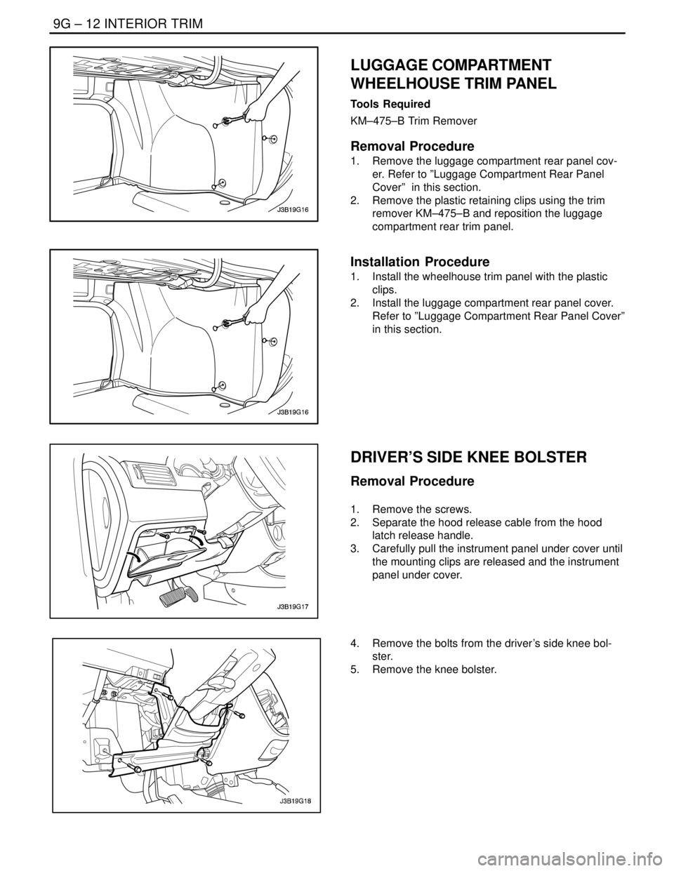
LUGGAGE COMPARTMENT
WHEELHOUSE TRIM PANEL
Tools Required
KM–475–B Trim Remover
Removal Procedure
1. Remove the luggage compartment rear panel cov-
er. Refer to ”Luggage Compartment Rear Panel
Cover” in this section.
2. Remove the plastic retaining clips using the trim
remover KM–475–B and reposition the luggage
compartment rear trim panel.
Installation Procedure
1. Install the wheelhouse trim panel with the plastic
clips.
2. Install the luggage compartment rear panel cover.
Refer to ”Luggage Compartment Rear Panel Cover”
in this section.
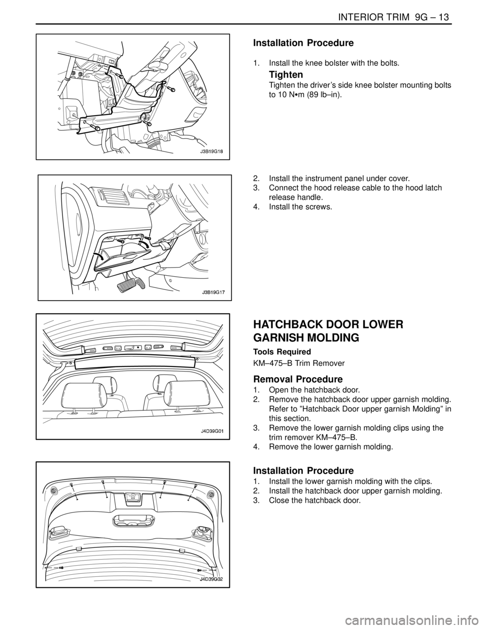
DRIVER’S SIDE KNEE BOLSTER
Removal Procedure
1. Remove the screws.
2. Separate the hood release cable from the hood
latch release handle.
3. Carefully pull the instrument panel under cover until
the mounting clips are released and the instrument
panel under cover.
4. Remove the bolts from the driver’s side knee bol-
ster.
5. Remove the knee bolster.
Page 2353 of 2643
INTERIOR TRIM 9G – 13
DAEWOO V–121 BL4
Installation Procedure
1. Install the knee bolster with the bolts.
Tighten
Tighten the driver’s side knee bolster mounting bolts
to 10 NSm (89 lb–in).
2. Install the instrument panel under cover.
3. Connect the hood release cable to the hood latch
release handle.
4. Install the screws.
HATCHBACK DOOR LOWER
GARNISH MOLDING
Tools Required
KM–475–B Trim Remover
Removal Procedure
1. Open the hatchback door.
2. Remove the hatchback door upper garnish molding.
Refer to ”Hatchback Door upper garnish Molding” in
this section.
3. Remove the lower garnish molding clips using the
trim remover KM–475–B.
4. Remove the lower garnish molding.
Installation Procedure
1. Install the lower garnish molding with the clips.
2. Install the hatchback door upper garnish molding.
3. Close the hatchback door.
Page 2462 of 2643

SECTION : 9R
BODY FRONT END
TABLE OF CONTENTS
SPECIFICATIONS9R–1 . . . . . . . . . . . . . . . . . . . . . . . . . .
Fastener Tightening Specifications 9R–1. . . . . . . . . . .
MAINTENANCE AND REPAIR9R–2 . . . . . . . . . . . . . . .
ON–VEHICLE SERVICE 9R–2. . . . . . . . . . . . . . . . . . . . .
Lubrication 9R–2. . . . . . . . . . . . . . . . . . . . . . . . . . . . . . . .
Fasteners 9R–2. . . . . . . . . . . . . . . . . . . . . . . . . . . . . . . .
Anticorrosion Materials 9R–2. . . . . . . . . . . . . . . . . . . . .
Front End Sealing 9R–2. . . . . . . . . . . . . . . . . . . . . . . . .
Cowl Vent Grille 9R–2. . . . . . . . . . . . . . . . . . . . . . . . . . .
Hood 9R–3. . . . . . . . . . . . . . . . . . . . . . . . . . . . . . . . . . . . . Hood Hinges 9R–3. . . . . . . . . . . . . . . . . . . . . . . . . . . . . .
Hood Prop Rod 9R–4. . . . . . . . . . . . . . . . . . . . . . . . . . . .
Hood Secondary Latch 9R–4. . . . . . . . . . . . . . . . . . . . .
Hood Latch Release Cable 9R–5. . . . . . . . . . . . . . . . . .
Notchback Radiator Grille 9R–5. . . . . . . . . . . . . . . . . . .
Hatchback Radiator Grille 9R–6. . . . . . . . . . . . . . . . . . .
Front Wheel Well Splash Shield 9R–6. . . . . . . . . . . . .
Fender 9R–7. . . . . . . . . . . . . . . . . . . . . . . . . . . . . . . . . . .
GENERAL DESCRIPTION AND SYSTEM
OPERATION9R–10 . . . . . . . . . . . . . . . . . . . . . . . . . . . . .
Body Front End 9R–10. . . . . . . . . . . . . . . . . . . . . . . . . .
SPECIFICATIONS
FASTENER TIGHTENING SPECIFICATIONS
ApplicationNSmLb–FtLb–In
A–Pillar Fender Bolt10–89
Fender Bolt (Front of Fascia)4–35
Front Bumper Fascia–to–Fender Bolt2.5–22
Hinge Bolts2720–
Hood–to–Hinge Bolts2720–
Hood Latch Bolts8–71
Hood Release Handle Nuts4–35
Lower Fender Bolt10–89
Radiator Grille Nuts4–35
Splash Shield screws2–18
Upper Fender Bolts10–89
Page 2465 of 2643
9R – 4IBODY FRONT END
DAEWOO V–121 BL4
Installation Procedure
Notice : Dissimilar metals in direct contact with each other
may corrode rapidly. Make sure to use the correct fasten-
ers to prevent premature corrosion.
1. Install the hinge with the bolts.
Tighten
Tighten the hinge bolts to 27 NSm (20 lb–ft).
2. Install the hood. Refer to ”Hood” in this section.
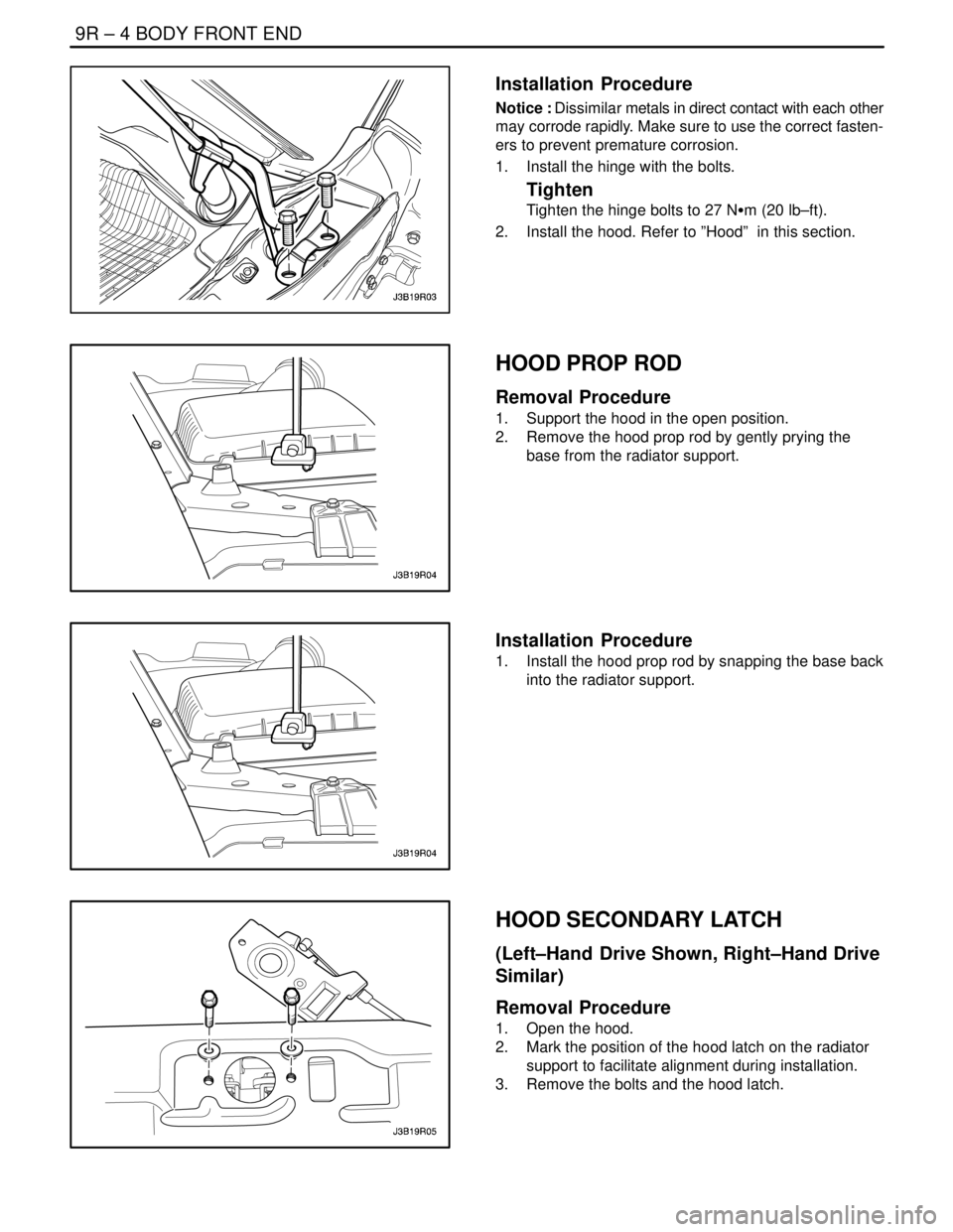
HOOD PROP ROD
Removal Procedure
1. Support the hood in the open position.
2. Remove the hood prop rod by gently prying the
base from the radiator support.
Installation Procedure
1. Install the hood prop rod by snapping the base back
into the radiator support.
HOOD SECONDARY LATCH
(Left–Hand Drive Shown, Right–Hand Drive
Similar)
Removal Procedure
1. Open the hood.
2. Mark the position of the hood latch on the radiator
support to facilitate alignment during installation.
3. Remove the bolts and the hood latch.
Page 2466 of 2643
BODY FRONT END 9R – 5
DAEWOO V–121 BL4
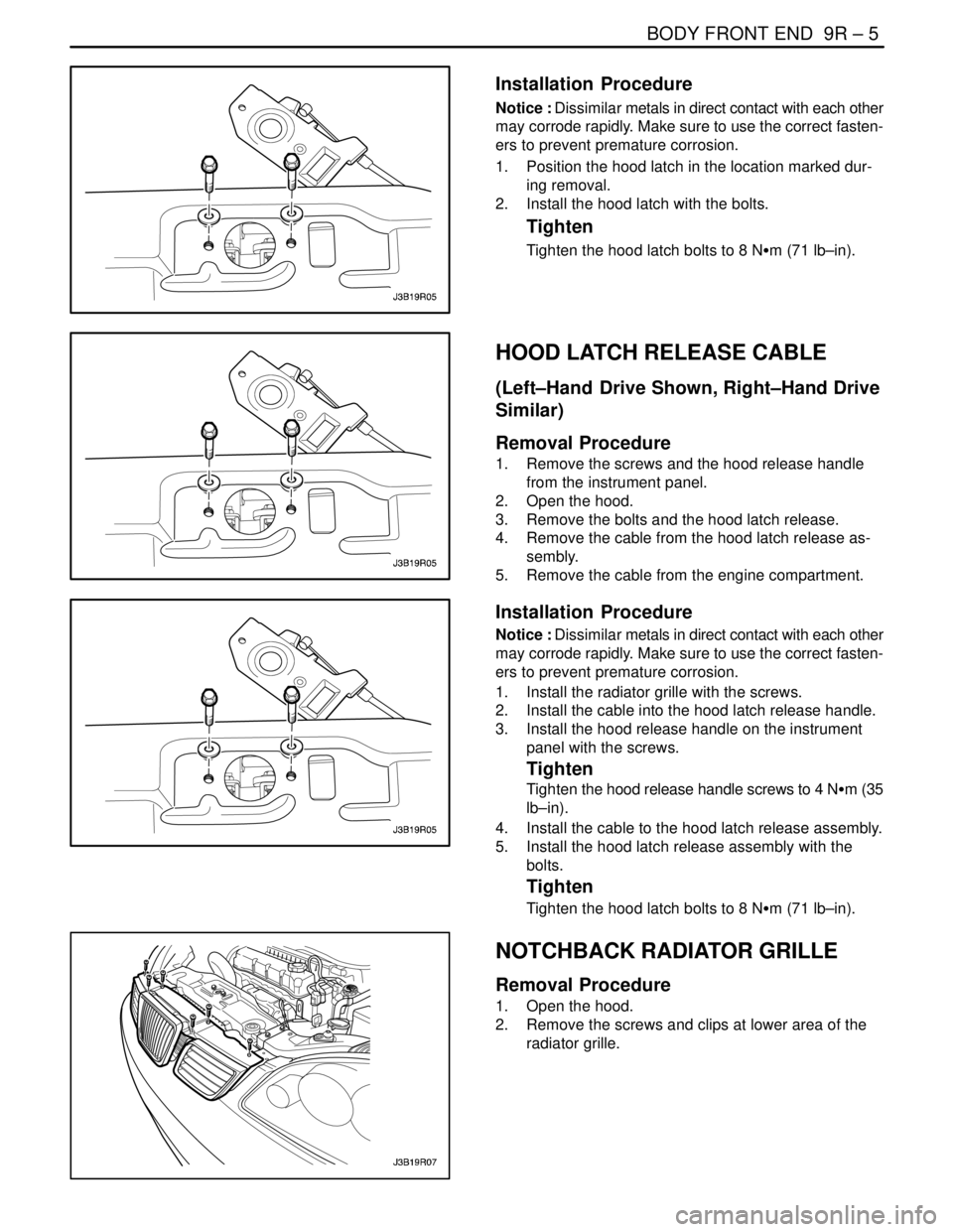
Installation Procedure
Notice : Dissimilar metals in direct contact with each other
may corrode rapidly. Make sure to use the correct fasten-
ers to prevent premature corrosion.
1. Position the hood latch in the location marked dur-
ing removal.
2. Install the hood latch with the bolts.
Tighten
Tighten the hood latch bolts to 8 NSm (71 lb–in).
HOOD LATCH RELEASE CABLE
(Left–Hand Drive Shown, Right–Hand Drive
Similar)
Removal Procedure
1. Remove the screws and the hood release handle
from the instrument panel.
2. Open the hood.
3. Remove the bolts and the hood latch release.
4. Remove the cable from the hood latch release as-
sembly.
5. Remove the cable from the engine compartment.
Installation Procedure
Notice : Dissimilar metals in direct contact with each other
may corrode rapidly. Make sure to use the correct fasten-
ers to prevent premature corrosion.
1. Install the radiator grille with the screws.
2. Install the cable into the hood latch release handle.
3. Install the hood release handle on the instrument
panel with the screws.
Tighten
Tighten the hood release handle screws to 4 NSm (35
lb–in).
4. Install the cable to the hood latch release assembly.
5. Install the hood latch release assembly with the
bolts.
Tighten
Tighten the hood latch bolts to 8 NSm (71 lb–in).
NOTCHBACK RADIATOR GRILLE
Removal Procedure
1. Open the hood.
2. Remove the screws and clips at lower area of the
radiator grille.
Page 2581 of 2643
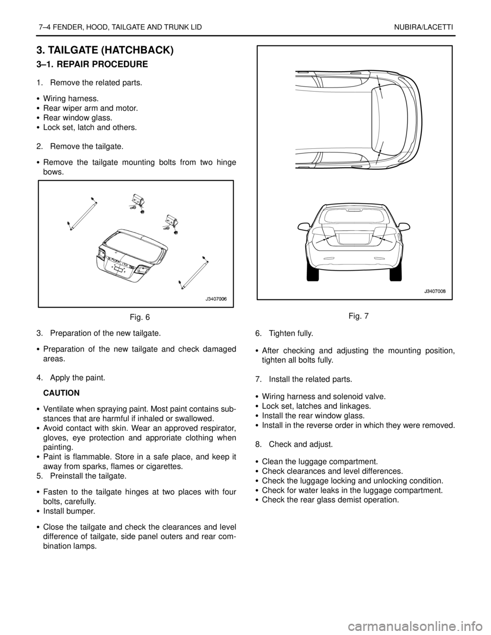
7–4 FENDER, HOOD, TAILGATE AND TRUNK LID NUBIRA/LACETTI
3. TAILGATE (HATCHBACK)
3–1. REPAIR PROCEDURE
1. Remove the related parts.
S Wiring harness.
S Rear wiper arm and motor.
S Rear window glass.
S Lock set, latch and others.
.
2. Remove the tailgate.
S Remove the tailgate mounting bolts from two hinge
bows.
Fig. 6
3. Preparation of the new tailgate.
S Preparation of the new tailgate and check damaged
areas.
.
4. Apply the paint.
CAUTION
S Ventilate when spraying paint. Most paint contains sub-
stances that are harmful if inhaled or swallowed.
S Avoid contact with skin. Wear an approved respirator,
gloves, eye protection and approriate clothing when
painting.
S Paint is flammable. Store in a safe place, and keep it
away from sparks, flames or cigarettes.
5. Preinstall the tailgate.
S Fasten to the tailgate hinges at two places with four
bolts, carefully.
S Install bumper.
S Close the tailgate and check the clearances and level
difference of tailgate, side panel outers and rear com-
bination lamps.Fig. 7
6. Tighten fully.
S After checking and adjusting the mounting position,
tighten all bolts fully.
.
7. Install the related parts.
S Wiring harness and solenoid valve.
S Lock set, latches and linkages.
S Install the rear window glass.
S Install in the reverse order in which they were removed.
.
8. Check and adjust.
S Clean the luggage compartment.
S Check clearances and level differences.
S Check the luggage locking and unlocking condition.
S Check for water leaks in the luggage compartment.
S Check the rear glass demist operation.