brake fluid DAEWOO NUBIRA 2004 Service Owner's Manual
[x] Cancel search | Manufacturer: DAEWOO, Model Year: 2004, Model line: NUBIRA, Model: DAEWOO NUBIRA 2004Pages: 2643, PDF Size: 80.54 MB
Page 1036 of 2643
MASTER CYLINDER 4B – 3
DAEWOO V–121 BL4
MAINTENANCE AND REPAIR
ON–VEHICLE SERVICE
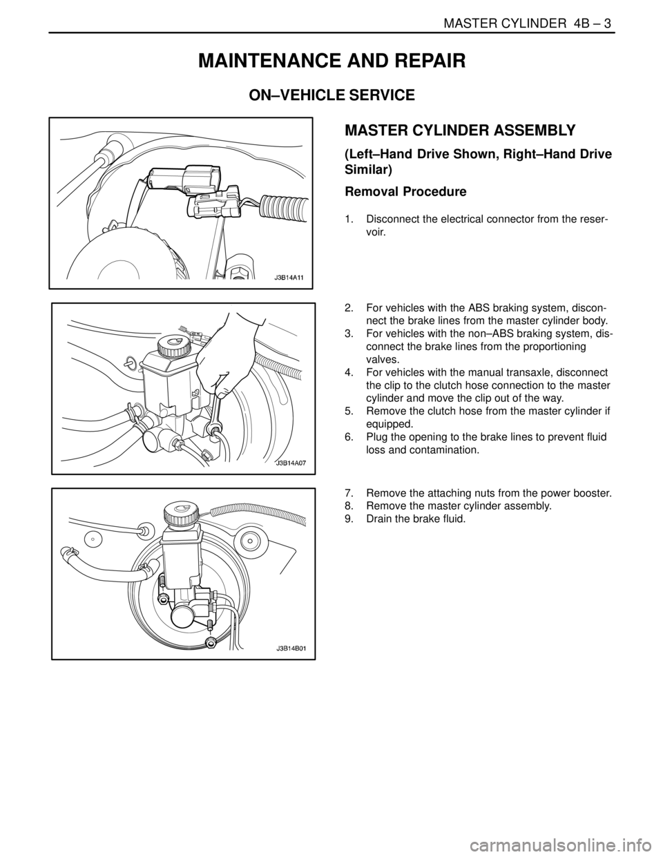
MASTER CYLINDER ASSEMBLY
(Left–Hand Drive Shown, Right–Hand Drive
Similar)
Removal Procedure
1. Disconnect the electrical connector from the reser-
voir.
2. For vehicles with the ABS braking system, discon-
nect the brake lines from the master cylinder body.
3. For vehicles with the non–ABS braking system, dis-
connect the brake lines from the proportioning
valves.
4. For vehicles with the manual transaxle, disconnect
the clip to the clutch hose connection to the master
cylinder and move the clip out of the way.
5. Remove the clutch hose from the master cylinder if
equipped.
6. Plug the opening to the brake lines to prevent fluid
loss and contamination.
7. Remove the attaching nuts from the power booster.
8. Remove the master cylinder assembly.
9. Drain the brake fluid.
Page 1037 of 2643
4B – 4IMASTER CYLINDER
DAEWOO V–121 BL4
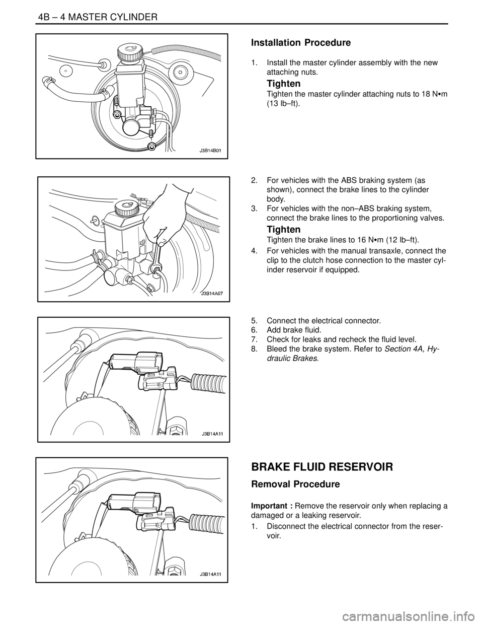
Installation Procedure
1. Install the master cylinder assembly with the new
attaching nuts.
Tighten
Tighten the master cylinder attaching nuts to 18 NSm
(13 lb–ft).
2. For vehicles with the ABS braking system (as
shown), connect the brake lines to the cylinder
body.
3. For vehicles with the non–ABS braking system,
connect the brake lines to the proportioning valves.
Tighten
Tighten the brake lines to 16 NSm (12 lb–ft).
4. For vehicles with the manual transaxle, connect the
clip to the clutch hose connection to the master cyl-
inder reservoir if equipped.
5. Connect the electrical connector.
6. Add brake fluid.
7. Check for leaks and recheck the fluid level.
8. Bleed the brake system. Refer to Section 4A, Hy-
draulic Brakes.
BRAKE FLUID RESERVOIR
Removal Procedure
Important : Remove the reservoir only when replacing a
damaged or a leaking reservoir.
1. Disconnect the electrical connector from the reser-
voir.
Page 1038 of 2643
MASTER CYLINDER 4B – 5
DAEWOO V–121 BL4
2. For vehicles with the manual transaxle, disconnect
the clip to the clutch hose connection to the master
cylinder, and move the clip out of the way.
3. Remove the clutch hose from the master cylinder.
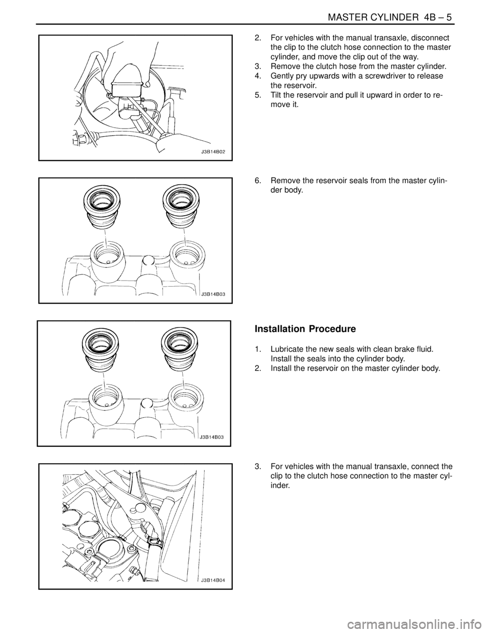
4. Gently pry upwards with a screwdriver to release
the reservoir.
5. Tilt the reservoir and pull it upward in order to re-
move it.
6. Remove the reservoir seals from the master cylin-
der body.
Installation Procedure
1. Lubricate the new seals with clean brake fluid.
Install the seals into the cylinder body.
2. Install the reservoir on the master cylinder body.
3. For vehicles with the manual transaxle, connect the
clip to the clutch hose connection to the master cyl-
inder.
Page 1039 of 2643

4B – 6IMASTER CYLINDER
DAEWOO V–121 BL4
4. Add brake fluid.
5. Raise and suitably support the vehicle.
6. Bleed the braking system. Refer to Section 4A, Hy-
draulic Brakes orSection 4F, Antilock Brake Sys-
tem.Bleed the clutch master cylinder. Refer to Sec-
tion 5C, Clutch.
7. Lower the vehicle.
8. Connect the reservoir electrical connector.
Page 1040 of 2643
MASTER CYLINDER 4B – 7
DAEWOO V–121 BL4
UNIT REPAIR
MASTER CYLINDER OVERHAUL
Disassembly Procedure
1. Remove the master cylinder. Refer to ”Master Cyl-
inder Assembly” in this section.
2. Remove the brake fluid reservoir. Refer to ”Brake
Fluid Reservoir” in this section.
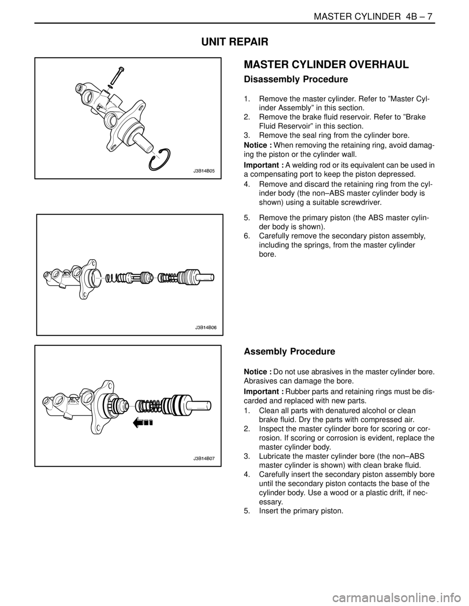
3. Remove the seal ring from the cylinder bore.
Notice : When removing the retaining ring, avoid damag-
ing the piston or the cylinder wall.
Important : A welding rod or its equivalent can be used in
a compensating port to keep the piston depressed.
4. Remove and discard the retaining ring from the cyl-
inder body (the non–ABS master cylinder body is
shown) using a suitable screwdriver.
5. Remove the primary piston (the ABS master cylin-
der body is shown).
6. Carefully remove the secondary piston assembly,
including the springs, from the master cylinder
bore.
Assembly Procedure
Notice : Do not use abrasives in the master cylinder bore.
Abrasives can damage the bore.
Important : Rubber parts and retaining rings must be dis-
carded and replaced with new parts.
1. Clean all parts with denatured alcohol or clean
brake fluid. Dry the parts with compressed air.
2. Inspect the master cylinder bore for scoring or cor-
rosion. If scoring or corrosion is evident, replace the
master cylinder body.
3. Lubricate the master cylinder bore (the non–ABS
master cylinder is shown) with clean brake fluid.
4. Carefully insert the secondary piston assembly bore
until the secondary piston contacts the base of the
cylinder body. Use a wood or a plastic drift, if nec-
essary.
5. Insert the primary piston.
Page 1041 of 2643
4B – 8IMASTER CYLINDER
DAEWOO V–121 BL4
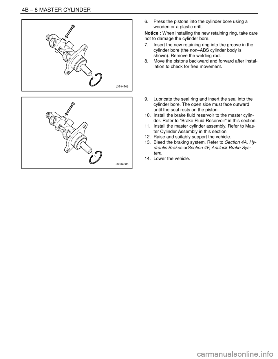
6. Press the pistons into the cylinder bore using a
wooden or a plastic drift.
Notice : When installing the new retaining ring, take care
not to damage the cylinder bore.
7. Insert the new retaining ring into the groove in the
cylinder bore (the non–ABS cylinder body is
shown). Remove the welding rod.
8. Move the pistons backward and forward after instal-
lation to check for free movement.
9. Lubricate the seal ring and insert the seal into the
cylinder bore. The open side must face outward
until the seal rests on the piston.
10. Install the brake fluid reservoir to the master cylin-
der. Refer to ”Brake Fluid Reservoir” in this section.
11. Install the master cylinder assembly. Refer to Mas-
ter Cylinder Assembly in this section
12. Raise and suitably support the vehicle.
13. Bleed the braking system. Refer to Section 4A, Hy-
draulic Brakes orSection 4F, Antilock Brake Sys-
tem.
14. Lower the vehicle.
Page 1042 of 2643

MASTER CYLINDER 4B – 9
DAEWOO V–121 BL4
GENERAL DESCRIPTION
AND SYSTEM OPERATION
MASTER CYLINDER
The master cylinder is designed for use in a diagonal–split
system. One front and one diagonally opposite rear brake
are served by the primary piston. The opposite front and
rear brakes are served by the secondary piston. The mas-
ter cylinder incorporates the functions of the standard dual
master cylinder, plus a low fluid level indicator and the pro-
portioning valves in the non–antilock braking system. The
proportioning valves limit the outlet pressure to the rear
brakes after a predetermined master cylinder pressure
has been reached.
Important :
S Replace all the components included in the repair
kits used to service this master cylinder.S Lubricate rubber parts with clean brake fluid to ease
assembly.
S Do not use lubricated shop air on brake parts, as
this may damage rubber components.
S If any hydraulic component is removed or discon-
nected, it may be necessary to bleed all or part of
the brake system.
S The torque values specified are for dry, unlubri-
cated fasteners.
S Perform all service operations on a clean bench,
free from all traces of mineral oil.
FLUID LEVEL SENSOR
The master cylinder is equipped with a fluid level sensor.
This sensor will activate the BRAKE light if a low fluid level
condition is detected. Once the fluid level is corrected, the
BRAKE light will go out.
Page 1051 of 2643
FRONT DISC BRAKES 4D – 3
DAEWOO V–121 BL4
MAINTENANCE AND REPAIR
ON–VEHICLE SERVICE
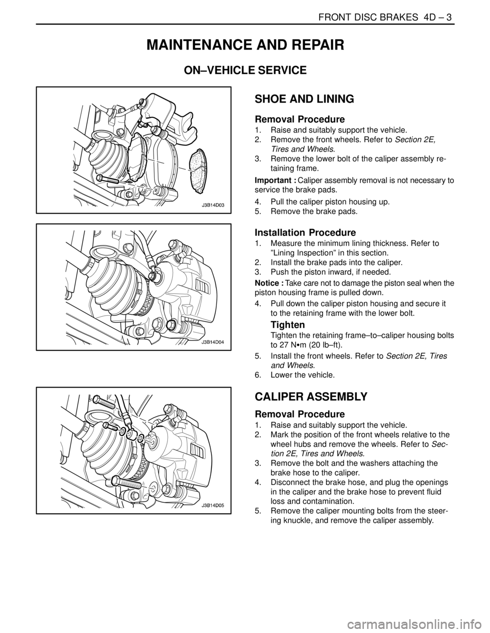
SHOE AND LINING
Removal Procedure
1. Raise and suitably support the vehicle.
2. Remove the front wheels. Refer to Section 2E,
Tires and Wheels.
3. Remove the lower bolt of the caliper assembly re-
taining frame.
Important : Caliper assembly removal is not necessary to
service the brake pads.
4. Pull the caliper piston housing up.
5. Remove the brake pads.
Installation Procedure
1. Measure the minimum lining thickness. Refer to
”Lining Inspection” in this section.
2. Install the brake pads into the caliper.
3. Push the piston inward, if needed.
Notice : Take care not to damage the piston seal when the
piston housing frame is pulled down.
4. Pull down the caliper piston housing and secure it
to the retaining frame with the lower bolt.
Tighten
Tighten the retaining frame–to–caliper housing bolts
to 27 NSm (20 lb–ft).
5. Install the front wheels. Refer to Section 2E, Tires
and Wheels.
6. Lower the vehicle.
CALIPER ASSEMBLY
Removal Procedure
1. Raise and suitably support the vehicle.
2. Mark the position of the front wheels relative to the
wheel hubs and remove the wheels. Refer to Sec-
tion 2E, Tires and Wheels.
3. Remove the bolt and the washers attaching the
brake hose to the caliper.
4. Disconnect the brake hose, and plug the openings
in the caliper and the brake hose to prevent fluid
loss and contamination.
5. Remove the caliper mounting bolts from the steer-
ing knuckle, and remove the caliper assembly.
Page 1052 of 2643
4D – 4IFRONT DISC BRAKES
DAEWOO V–121 BL4
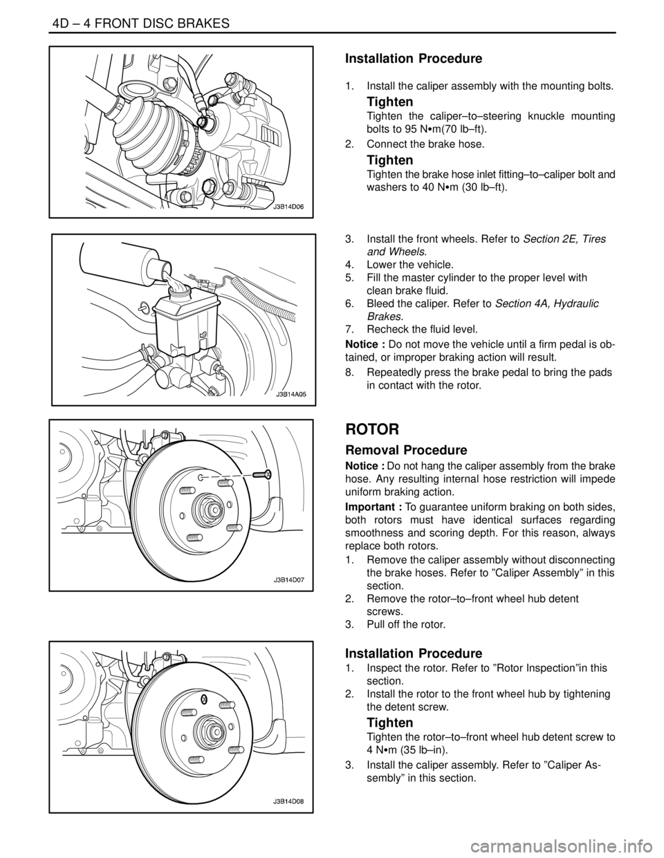
Installation Procedure
1. Install the caliper assembly with the mounting bolts.
Tighten
Tighten the caliper–to–steering knuckle mounting
bolts to 95 NSm(70 lb–ft).
2. Connect the brake hose.
Tighten
Tighten the brake hose inlet fitting–to–caliper bolt and
washers to 40 NSm (30 lb–ft).
3. Install the front wheels. Refer to Section 2E, Tires
and Wheels.
4. Lower the vehicle.
5. Fill the master cylinder to the proper level with
clean brake fluid.
6. Bleed the caliper. Refer to Section 4A, Hydraulic
Brakes.
7. Recheck the fluid level.
Notice : Do not move the vehicle until a firm pedal is ob-
tained, or improper braking action will result.
8. Repeatedly press the brake pedal to bring the pads
in contact with the rotor.
ROTOR
Removal Procedure
Notice : Do not hang the caliper assembly from the brake
hose. Any resulting internal hose restriction will impede
uniform braking action.
Important : To guarantee uniform braking on both sides,
both rotors must have identical surfaces regarding
smoothness and scoring depth. For this reason, always
replace both rotors.
1. Remove the caliper assembly without disconnecting
the brake hoses. Refer to ”Caliper Assembly” in this
section.
2. Remove the rotor–to–front wheel hub detent
screws.
3. Pull off the rotor.
Installation Procedure
1. Inspect the rotor. Refer to ”Rotor Inspection”in this
section.
2. Install the rotor to the front wheel hub by tightening
the detent screw.
Tighten
Tighten the rotor–to–front wheel hub detent screw to
4 NSm (35 lb–in).
3. Install the caliper assembly. Refer to ”Caliper As-
sembly” in this section.
Page 1055 of 2643
FRONT DISC BRAKES 4D – 7
DAEWOO V–121 BL4
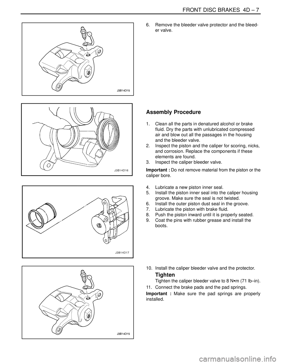
6. Remove the bleeder valve protector and the bleed-
er valve.
Assembly Procedure
1. Clean all the parts in denatured alcohol or brake
fluid. Dry the parts with unlubricated compressed
air and blow out all the passages in the housing
and the bleeder valve.
2. Inspect the piston and the caliper for scoring, nicks,
and corrosion. Replace the components if these
elements are found.
3. Inspect the caliper bleeder valve.
Important : Do not remove material from the piston or the
caliper bore.
4. Lubricate a new piston inner seal.
5. Install the piston inner seal into the caliper housing
groove. Make sure the seal is not twisted.
6. Install the outer piston dust seal in the groove.
7. Lubricate the piston with brake fluid.
8. Push the piston inward until it is properly seated.
9. Coat the pins with rubber grease and install the
boots.
10. Install the caliper bleeder valve and the protector.
Tighten
Tighten the caliper bleeder valve to 8 NSm (71 lb–in).
11. Connect the brake pads and the pad springs.
Important : Make sure the pad springs are properly
installed.