wheel torque DAEWOO NUBIRA 2004 Service Owner's Manual
[x] Cancel search | Manufacturer: DAEWOO, Model Year: 2004, Model line: NUBIRA, Model: DAEWOO NUBIRA 2004Pages: 2643, PDF Size: 80.54 MB
Page 907 of 2643
2A – 6ISUSPENSION DIAGNOSIS
DAEWOO V–121 BL4
S A high front trim height. This height would increase
the drive axle angle and could cause wobble at
speeds between 24 to 48 km/h (15 to 30 mph).
S Binding or a tight drive axle joint. A tight drive axle
joint or a high front trim height may also cause a
wobble at speeds between 24 to 48 km/h (15 to 30
mph).
S Incorrect, worn, or loose engine mounts causing
adverse drive angles.
Refer to ”General Diagnosis” in this section for actions to
remedy these problems.
Conditions that may produce an effect similar to torque
steer include:
S Incorrect front or rear alignment.
S Frame misalignment or defect.
S Front suspension damage.
S Incorrectly mounted rear crossmember.
TAPERED ROLLER BEARING
Perform the following test to check for looseness in the
hub and bearing assembly on vehicles equipped with rear
disc brakes:
1. Raise and suitably support the vehicle.
2. Remove the rear wheel. Refer to Section 2E, Tires
and Wheels.
3. Remove the brake disc caliper and the brake rotor.
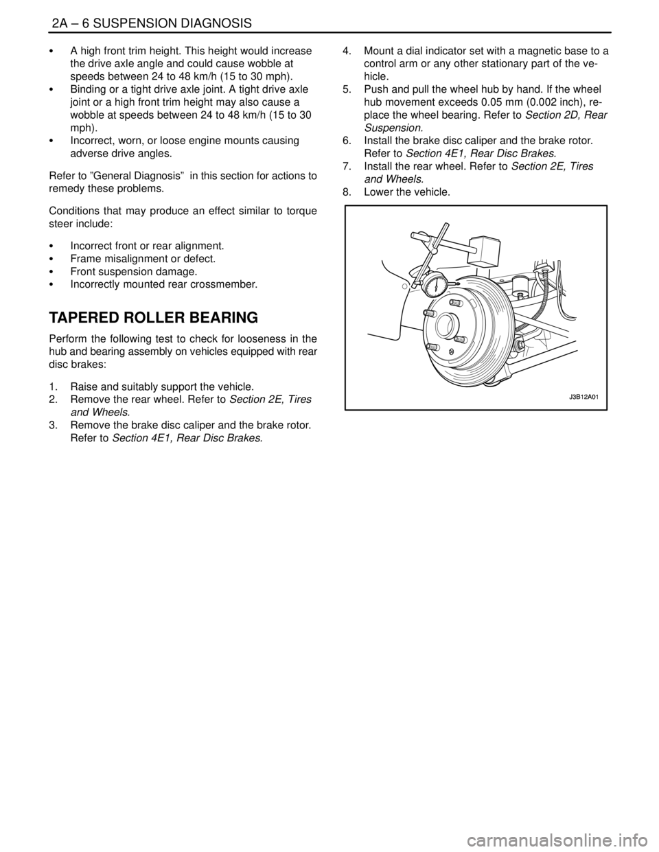
Refer to Section 4E1, Rear Disc Brakes.4. Mount a dial indicator set with a magnetic base to a
control arm or any other stationary part of the ve-
hicle.
5. Push and pull the wheel hub by hand. If the wheel
hub movement exceeds 0.05 mm (0.002 inch), re-
place the wheel bearing. Refer to Section 2D, Rear
Suspension.
6. Install the brake disc caliper and the brake rotor.
Refer to Section 4E1, Rear Disc Brakes.
7. Install the rear wheel. Refer to Section 2E, Tires
and Wheels.
8. Lower the vehicle.
Page 923 of 2643

2C – 6IFRONT SUSPENSION
DAEWOO V–121 BL4
BALL JOINT AND KNUCKLE
Ball Joint Inspection
1. Raise the front of the vehicle to allow the front sus-
pension to hang free.
2. Grasp the tire at the top and the bottom.
3. Move the top of the tire in an in–and–out motion.
4. Look for any horizontal movement of the knuckle
relative to the control arm.
5. Ball joints must be replaced under the following
conditions:
S The joint is loose.
S The ball seal is cut.
S The ball stud is disconnected from the knuckle.
S The ball stud is loose at the knuckle.
S The ball stud can be twisted in its socket with
finger pressure.
Ball Stud Inspection
Make sure to check the tightness of the ball stud in the
knuckle boss during each inspection of the ball joint. One
way to inspect the ball stud for wear is to shake the wheel
and feel for movement of the stud end at the knuckle boss.Another way to inspect the ball stud for wear is to check
the fastener torque at the pinch nut. A loose nut can indi-
cate a stressed stud or a hole in the knuckle boss.
Worn or damaged ball joints and knuckles must be re-
placed.
EXCESSIVE FRICTION CHECK
Use the following procedure to check for excessive friction
in the front suspension:
1. Enlist the help of another technician to lift up on the
front bumper, raising the vehicle as high as pos-
sible.
2. Slowly release the bumper, allowing the vehicle to
assume its normal trim height. See ”General Speci-
fications” in this section.
3. Measure the distance from the street level to the
center of the bumper.
4. Push down on the bumper, release slowly, and al-
low the vehicle to assume its normal trim height.
5. Measure the distance from the street level to the
center of the bumper.
6. The difference between the two measurements
should be less than 12.7 mm (0.5 inch). If the differ-
ence exceeds this limit, inspect the control arms,
the struts, and the ball joints for damage or wear.
Page 965 of 2643

TIRES AND WHEELS 2E – 3
DAEWOO V–121 BL4
MAINTENANCE AND REPAIR
ON–VEHICLE SERVICE
WHEEL
Removal Procedure
1. Loosen the wheel bolts.
2. Raise and suitably support the vehicle.
3. Remove the wheel bolts.
Notice : Never use heat to loosen a tight wheel. It can
shorten the life of the wheel, the wheel nuts and the wheel
bearings. Excessive force, such as hammering the wheel
or tire, can also cause damage and is not recommended.
Slight tapping of the wheel sidewall with one’s hand or with
a rubber mallet is acceptable.
4. Remove the wheel.
Difficulty in removing the wheels from the vehicle can be
due to foreign material or to a tight fit between the wheel
centerhole and the hub or the rotor. These wheels can be
removed by
5. Retightening the wheel bolts on the affected wheel
and then loosening the wheel bolts by two turns.
6. Lowering the vehicle and rocking it from side to side
as hard as possible, using one or more person’s
body weight to loosen the wheel.
7. Raising the vehicle and removing the wheel.
CAUTION : Do not allow the penetrating oil to get on
the vertical surfaces between the wheel and the drum
(or rotor) because penetrating oil in this area could
cause the wheel to work loose as the vehicle is driven,
resulting in loss of control and an injury accident.
Penetrating oil is not effective in removing tight wheels. If
it is used, however, apply it sparingly and only to the
wheel’s centerhole area.
Installation Procedure
Notice : Before installing the wheels, remove any buildup
of corrosion on the wheel mounting surface and the brake
drum or the rotor mounting surface by scraping and brush-
ing them with a wire brush. Installing the wheels without
good metal–to–metal contact at the mounting surfaces
can cause the wheel nuts to loosen, which can later allow
a wheel to come off while the vehicle is moving. Wheel
bolts must be tightened in sequence and to the proper
torque to avoid bending the wheel, the brake drum or the
rotor.
1. Mount the wheel.
2. Install the wheel bolts in the sequence shown. Do
not tighten the wheel bolts.
3. Lower the vehicle.
Tighten
Tighten the wheel bolts to 100 NSm (74 lb–ft).
Page 973 of 2643

TIRES AND WHEELS 2E – 11
DAEWOO V–121 BL4
pacity, diameter, rim width, offset, and mounting configu-
ration. A wheel of improper size or type may affect wheel
and bearing life, brake cooling, speedometer/odometer
calibration, vehicle ground clearance, and tire clearance
to the body and the chassis. The wheel offset is 49 ± 1 mm
(1.93 ± 0.04 inches). Steel wheels may be identified by a
two– or three–letter code stamped into the rim near the
valve stem. Alloy wheels should have the code, the part
number, and the manufacturer ID cast into the back side.
INFLATION O TIRES
The pressure recommended for any vehicle line is careful-
ly calculated to give a satisfactory ride, handling, tread life,
and load–carrying capacity.
Tire pressure should be checked monthly or before any
extended trip. Check the tires when they are cold, after the
vehicle has sat for 3 hours or more, or has been driven less
than 1 mile. Set the tire pressure to the specifications on
the tire label located on the rear face of the driver’s door.
Tire inflation pressure is also given under ”Tire Size and
Pressure Specifications” in this section.
Valve caps or extensions should be on the valves to keep
dust and water out.
For sustained driving at speeds up to 140 km/h (85 mph),
inflate the tires to the pressure recommended on the tire.
Sustained driving at speeds faster than 140 km/h (85mph), even if permitted by law, is not advised unless the
vehicle has special high–speed tires available from many
tire dealers. Tire pressures may increase as much as 41
kPa (6 psi) when the tires are hot.
Higher than recommended tire pressure can cause
S Hard ride.
S Tire bruising or damage.
S Rapid tread wear at the center of the tire.
Lower than recommended pressure can cause
S Tire squeal on turns.
S Hard steering.
S Rapid and uneven wear on the edges of the tread.
S Tire rim bruises and rupture.
S Tire cord breakage.
S High tire temperatures.
Unequal tire pressures on same axle can cause
S Uneven braking.
S Steering lead.
S Reduced handling.
S Swerve on acceleration.
S Torque steer.
Page 1081 of 2643

4E2 – 12IREAR DRUM BRAKES
DAEWOO V–121 BL4
GENERAL DESCRIPTION
AND SYSTEM OPERATION
DRUM BRAKES
This drum brake assembly is a leading/trailing shoe de-
sign. Both brake shoes are held against the wheel cylinder
pistons by the lower return spring and the fixed anchor
plate near the lower return spring. When the brakes are
applied, the wheel cylinder pistons move both shoes out
to contact the drum. With forward wheel rotation, the for-
ward brake shoe will wrap into the drum and become self–
energized. With reverse wheel rotation, the rear brake
shoe is self–energized. Force from the brake shoes is
transferred to the anchor plate through the backing plate
to the axle flange. Adjustment is automatic and occurs on
any service brake application. Do not switch the positionof shoes that have been in service, as this may render the
self–adjustment feature inoperative and result in in-
creased pedal travel.
Notice : To avoid damaging the vehicle, observe the fol-
lowing directions:
S Replace all the components included in the repair
kits used to service this drum brake.
S Do not use lubricated shop air on the brake parts,
as damage to the rubber components may result.
S If any hydraulic component is removed or discon-
nected, it may be necessary to bleed all or part of
the braking system.
S Replace the shoe and linings in axle sets only.
S The torque values specified are for dry, unlubri-
cated fasteners.
S Perform service operations on a clean bench that is
free from all mineral oil materials.
Page 1352 of 2643

ZF 4 HP 16 AUTOMATIC TRANSAXLE 5A1 – 3
DAEWOO V–121 BL4
Important Measurement/Adjustment 5A1–230. . . . . . .
GENERAL DESCRIPTION AND SYSTEM
OPERATION5A1–232 . . . . . . . . . . . . . . . . . . . . . . . . . . . Mechanical Components 5A1–232. . . . . . . . . . . . . . . . .
Electronical Components 5A1–236. . . . . . . . . . . . . . . .
TCM Inputs That Affect the 4HP 16
Transaxle 5A1–241. . . . . . . . . . . . . . . . . . . . . . . . . . .
INTRODUCTION
ZF 4HP 16 AUTOMATIC TRANSAXLE
The ZF 4 HP 16 is a four–speed automatic transaxle de-
signed for cars with front–wheel drive and a transversely
mounted engine.
The transaxle has a hydrodynamic torque converter with
a controlled slip lock–up clutch.
A planetary gear train establishes the mechanical gear ra-
tios. The integral constant ratio can be adapted to the en-
gine’s power output and the vehicle’s weight. The elec-
tronic–hydraulic control makes controlled power shifts and
various shift programs possible. In selector lever position
”P”, the output is locked mechanically.The special feature of this transaxle is that it operates with-
out freewheels. Shifting between individual gears takes
place by means of overlapping clutch engagement and re-
lease.
The advantage of overlap shifting is as follows:
– The transaxle can be of more compact design
and is lighter on account of the absence of free-
wheels and the lower number of shift elements
– Lower drag losses, i.e. higher efficiency
– Lower peak torques acting on the components
and driveline.
However, overlap shifting necessitates high–performance
hardware and software, and precision engine signals.
Page 1354 of 2643

ZF 4 HP 16 AUTOMATIC TRANSAXLE 5A1 – 5
DAEWOO V–121 BL4
SPECIFICATIONS
GENERAL SPECIFICATIONS
Definition
Transaxle Type4–speed with four–wheel drive and transverse engine
Input Torque240 NSm (177 lb–ft)
Transaxle Weight76kg (168 lb)
Torque Converter Capacity9.72kg (21.4 lb)
Transaxle Fluid Type (manufacture company)ESSO LT 71141 or TOTAL ATF H50235
Transaxle Fluid Capacity7.3qt (6.9L)
TRANSAXLE GEAR RATIO
GearRatio
First2.719
Second1.487
Third1.000
Fourth0.717
Reverse 2.529
Final3.945:1
FLUID CAPACITY
LitresQuarts
Bottom Pan Removal44.2
Complete Overhaul6.97.3
Torque Converter Removal22.1
(Measurements are approximate)
FASTENER TIGHTENING SPECIFICATIONS
ApplicationNSmLb–FtLb–In
Bearing Plate Bolts23.517.5–
Slotted Nut220162–
Rear Cover Attachment Bolts23.517.5–
Baffle Plate Attachment Bolts10–89
Park/Neutral Position Switch10–89
Fluid Pump Connecting Bolts10–89
Fluid Filter Housing Cover Attachment Bolts10–89
Input Speed sensor Attachment Bolts8–71
Output Speed Sensor Attachment Bolts8–71
Valve Body Bolts8–71
Valve Body Upper & Lower Fixing Bolts6–53
Fluid Pan Connecting Bolts6–53
Fluid Pan Drain Plug4533–
Page 1398 of 2643

ZF 4 HP 16 AUTOMATIC TRANSAXLE 5A1 – 49
DAEWOO V–121 BL4
Functional Check Procedure
Inspect
1. Install a tachometer or scan tool.
2. Operate the vehicle unit proper operating tempera-
ture is reached.
3. Drive the vehicle at 80 to 88km/h (50 to 55 mph)
with light throttle(road load).
4. Maintaining throttle position, lightly touch the brake
pedal and check for release of the TCC and a slight
increase in engine speed(rpm).
5. Release the brake slowly accelerate and check for
a reapply of the Lock up clutch and a slight de-
crease in engine speed(rpm).
Torque Converter Evaluation
Torque Converter Stator
The torque converter stator roller clutch can have one of
two different type malfunctions :
A. Stator assembly freewheels in both directions.
B. Stator assembly remains Locked up at all times.
Condition A – Poor Acceleration Low
Speed
The car tends to have poor acceleration from a stand still.
At speeds above 50 to 55km/h(30 to 35mph), the car may
act normal. If poor acceleration is noted, it should first be
determined that the exhaust system is not blocked, and
the transaxle is in 1st(First) gear when starting out.
If the engine freely accelerates to high rpm in N(Neutral),
it can be assumed that the engine and exhaust system are
normal. Checking for poor performance in ”Drive” and ”Re-
verse” will help determine if the stator is freewheeling at all
times.
Condition B – Poor Acceleration High
Speed
Engine rpm and car speed limited or restricted at high
speeds. Performance when accelerating from a standstill
is normal. Engine may overheat. Visual examination of the
converter may reveal a blue color from overheating.
If the converter has been removed, the stator roller clutch
can be checked by inserting two fingers into the splined in-
ner race of the roller clutch and trying to turn freely clock-
wise, but not turn or be very difficult to turn counter clock-
wise.
Noise
Torque converter whine is usually noticed when the ve-
hicle is stopped and the transaxle is in ”Drive” or ”Re-
verse”. The noise will increase when engine rpm is in-
creased. The noise will stop when the vehicle is moving or
when the torque converter clutch is applied because both
halves of the converter are turning at the same speed.
Perform a stall test to make sure the noise is actually com-
ing from the converter :1. Place foot on brake.
2. Put gear selector in ”Drive”.
3. Depress accelerator to approximately 1200rpm for
no more than six seconds.
Notice : If the accelerator is depressed for more than six
seconds, damage to the transaxle may occur.
A torque converter noise will increase under this load.
Important : This noise should not be confused with pump
whine noise which is usually noticeable in P (Park), N
(Neutral) and all other gear ranges. Pump whine will vary
with pressure ranges.
The torque converter should be replaced under any of the
following conditions:
S External leaks in the hub weld area.
S Converter hub is scored or damaged.
S Converter pilot is broken, damaged or fits poorly
into crankshaft.
S Steel particles are found after flushing the cooler
and cooler lines.
S Pump is damaged or steel particles are found in the
converter.
S Vehicle has TCC shudder and/or no TCC apply.
Replace only after all hydraulic and electrical diag-
noses have been made.(Lock up clutch material
may be glazed.)
S Converter has an imbalance which cannot be cor–
rected. (Refer To Converter Vibration Test Proce-
dure.)
S Converter is contaminated with engine coolant con-
taining antifreeze.
S Internal failure of stator roller clutch.
S Excess end play.
S Heavy clutch debris due to overheating (blue con-
verter).
S Steel particles or clutch lining material found in fluid
filter or on magnet when no internal parts in unit are
worn or damaged(indicates that lining material
came from converter).
The torque converter should not be replace if :
S The oil has an odor, is discolored, and there is no
evidence of metal or clutch facing particles.
S The threads in one or more of the converter bolt
holes are damaged.
–correct with thread insert.
S Transaxle failure did not display evidence of dam-
age or worn internal parts, steel particles or clutch
plate lining material in unit and inside the fluid filter.
S Vehicle has been exposed to high mileage(only).
The exception may be where the Lock up clutch
damper plate lining has seen excess wear by ve-
hicles operated in heavy and/or constant traffic,
such as taxi, delivery or police use.
Lock–Up Clutch Shudder Diagnosis
The key to diagnosing lock–up clutch(TCC) shudder is to
note when it happens and under what conditions.
Page 1406 of 2643

ZF 4 HP 16 AUTOMATIC TRANSAXLE 5A1 – 57
DAEWOO V–121 BL4
Symptom ActionPossible Cause
Sealing Ring Selector ShaftS Check sealing ring.
S Replace sealing ring as described in the repair
instruction.
O–ring at Socket OutletS Check O–ring.
S Replace O–ring as described in the repair in-
struction.
O–ring and Speed Sensor ConnectionS Check O–ring.
S Replace O–ring as described in the repair in-
struction.
Oil Leak Incorrectly IdentifiedS No oil leak is possible at this point.
Speed Sensor Itself Is LeakingS Check speed sensor.
S Replace speed sensor as described in the re-
pair instruction.
Hair Line Crack at the Piping in the Con-
nection Area, Sealing Ring Fit in Trans-
axle HousingS Pressurize the line with compressed air and
check it.
S Replace lines as described in the repair in-
struction.
O–ring Defective, IncorrectCheck O–ring.
Replace O–rings as described in the repair instruc-
tion.
Plug LooseCheck the Tightening Torque for the screw plug.
Tighten to torque specified in the repair instruction.
Noise
SymptomPossible CauseAction
NoiseTFT Level Too LowS When the TFT level is too low, the gear wheels
from the transaxle oil pump might generate
noise.
S Check the TFT level as described in the repair
instruction and fill to the proper level.
Monolith in Catalytic Converter Has
BrokenS Check according to the exhaust gas diagnostic
procedure or by shaking the catalytic converter
casing.
S Replace catalytic converter if necessary.
Noise from Auxiliaries (e.g. exhaust
system, alternator, drive shafts.)S Check these components; if necessary, elimi-
nate the faults as described in the repair in-
struction
Noise from Tires or Wheel BearingsS Eliminate fault if necessary
Noise from Planetary GearsS Whistling noise on traction and overrun(in first
gear only)caused by high rotating speeds(func-
tionally unavoidable)
Cumulative Tooth Backlash in the Com-
plete Drive LineS Production status. Customer must be con-
vinced.
Jerky Noise of the Parking Lock (e.g.
when the car is standing on a gradient)S Load–reversal reaction
S Apply the handbrake before selection the park-
ing Lock (position P)
Page 1473 of 2643

5A1 – 124IZF 4 HP 16 AUTOMATIC TRANSAXLE
DAEWOO V–121 BL4
RangePark/
Neutr
alRever
seD321
GearNR1st2nd3rd4th1st2nd3rd1st2nd1st
Solenoid Valve
1ONON/
OFFON/
OFFON/
OFFON/
OFFON/
OFFON/
OFFON/
OFFON/
OFFON/
OFFON/
OFFON/
OFF
Solenoid Valve
2ONONONOFFOFFOFFONOFFOFFONOFFON
Line Pressure
Control Sole-
noid Valve 3
(EDS 3)OFFOFFOFFONON/
OFFON/
OFFOFFONON/
OFFOFFONOFF
Line Pressure
Control Sole-
noid Valve 4
(EDS 4)ONOFFONONONOFFONONONONONON
Line Pressure
Control Sole-
noid Valve 5
(EDS 5)OFFOFFONONOFFOFFONONOFFONONON
Line Pressure
Control Sole-
noid Valve 6
(EDS 6)ONOFFONONONOFFONONONONONON
Brake BAAAAAAAA
Brake CH
Brake DH
Clutch EAAAAAA
Brake FHHHHHHH
Lock–up
ClutchA
A = Applied
H = Holding
ON = The solenoid is energized.
OFF = The solenoid is de–energized.
** = Manual Second–Third gear is only available above approximately 100 km/h (62 mph).
*** = Manual First–Second gear is only available above approximately 60 km/h (37 mph).
Note : Manual First–Third gear is also possible at high vehicle speed as a safety feature.
DIAGNOSTIC TROUBLE CODE(DTC) P0781
1–2 SHIFT MALFUNCTION
Circuit Description
The special feature of 4HP 16 Auto Transaxle is that it op-
erates without freewheels. Shifting between individual
gears takes place by means of overlapping clutch engage-
ment and release.
The advantage of overlap shifting are as follows:
–The transaxle can be of more compact design and
is lighter on account of the absence of freewheels
and the lower number of shift elements.–Lower drag losses, i.e. higher efficiency.
–Lower peak torque acting on the components and
driveline.
However, overlap shifting necessitates high–performance
hardware and software, and precision engine signals.
Conditions for Setting The DTC
S Transmission oil temperature is greater than –10°C
(14°F).
S Selector lever is not N(Neutral), P(Park) position.
S System voltage is greater than 9 volts.