gear shift DAEWOO NUBIRA 2004 Service Manual Online
[x] Cancel search | Manufacturer: DAEWOO, Model Year: 2004, Model line: NUBIRA, Model: DAEWOO NUBIRA 2004Pages: 2643, PDF Size: 80.54 MB
Page 1672 of 2643
5A2 – 82IAISIN AUTOMATIC TRANSAXLE
DAEWOO V–121 BL4
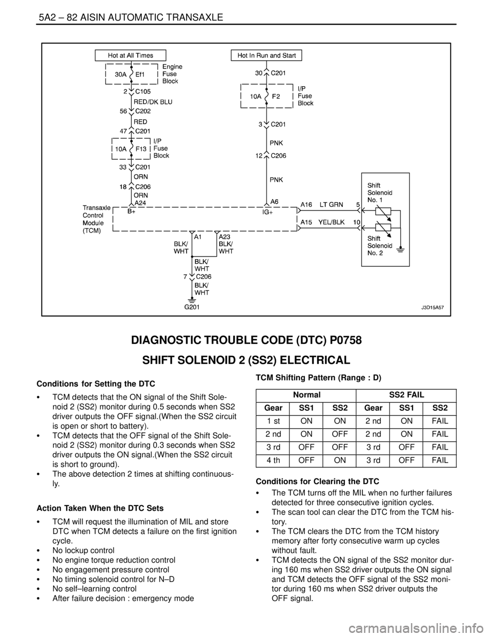
DIAGNOSTIC TROUBLE CODE (DTC) P0758
SHIFT SOLENOID 2 (SS2) ELECTRICAL
Conditions for Setting the DTC
S TCM detects that the ON signal of the Shift Sole-
noid 2 (SS2) monitor during 0.5 seconds when SS2
driver outputs the OFF signal.(When the SS2 circuit
is open or short to battery).
S TCM detects that the OFF signal of the Shift Sole-
noid 2 (SS2) monitor during 0.3 seconds when SS2
driver outputs the ON signal.(When the SS2 circuit
is short to ground).
S The above detection 2 times at shifting continuous-
ly.
Action Taken When the DTC Sets
S TCM will request the illumination of MIL and store
DTC when TCM detects a failure on the first ignition
cycle.
S No lockup control
S No engine torque reduction control
S No engagement pressure control
S No timing solenoid control for N–D
S No self–learning control
S After failure decision : emergency modeTCM Shifting Pattern (Range : D)
Normal
SS2 FAIL
GearSS1SS2GearSS1SS2
1 stONON2 ndONFAIL
2 ndONOFF2 ndONFAIL
3 rdOFFOFF3 rdOFFFAIL
4 thOFFON3 rdOFFFAIL
Conditions for Clearing the DTC
S The TCM turns off the MIL when no further failures
detected for three consecutive ignition cycles.
S The scan tool can clear the DTC from the TCM his-
tory.
S The TCM clears the DTC from the TCM history
memory after forty consecutive warm up cycles
without fault.
S TCM detects the ON signal of the SS2 monitor dur-
ing 160 ms when SS2 driver outputs the ON signal
and TCM detects the OFF signal of the SS2 moni-
tor during 160 ms when SS2 driver outputs the
OFF signal.
Page 1681 of 2643

AISIN AUTOMATIC TRANSAXLE 5A2 – 91
DAEWOO V–121 BL4
DIAGNOSTIC TROUBLE CODE (DTC) P1791
THROTTLE POSITION SIGNAL ERROR
Conditions for Setting the DTC
S TCM detects that malfunction of throttle position
signal for 2 seconds continuously.
S No DTC U2105
Action Taken When the DTC Sets
S TCM will request the illumination of MIL and store
DTC when TCM detects a failure on the first ignition
cycle.
S TCM judges the throttle opening is 0% for shift
point control.
S TCM judges the throttle opening is 100% for line
pressure control.
S No lock–up
S No 4th gear
S No self–learning controlS No timing solenoid control for N–D
Conditions for Clearing the DTC
S The TCM turns off the MIL when no further failures
detected for three consecutive ignition cycles.
S The scan tool can clear the DTC from the TCM his-
tory.
S The TCM clears the DTC from the TCM history
memory after forty consecutive warm up cycles
without fault.
Cause of Failure
S Wiring harness or connector between ECM and
TCM
S ECM
S TCM
Page 1685 of 2643

AISIN AUTOMATIC TRANSAXLE 5A2 – 95
DAEWOO V–121 BL4
DIAGNOSTIC TROUBLE CODE (DTC) U2105
CAN ERROR
Conditions for Setting the DTC
S TCM detects that the BUS OFF signal. This detec-
tion is continued for 0.2 seconds.
S TCM detects that nothing of ECM signal on CAN
BUS for 0.2 seconds. This detection is continued
for 2.0 seconds.
Action Taken When the DTC Sets
S TCM will request the illumination of MIL and store
DTC when TCM detects a failure on the first ignition
cycle.
S TCM judges the throttle opening is 0% for shift
point and lock–up point control.
S TCM judges the throttle opening is 100% for line
pressure control.
S No lock–upS No self–learning control
S No 4th gear
S TCM judges the engine revolution is 0 rpm.
Conditions for Clearing the DTC
S The TCM turns off the MIL when no further failures
detected for three consecutive ignition cycles.
S The scan tool can clear the DTC from the TCM his-
tory.
S TCM detects the BUS normal signal for 2 seconds
continuously.
Cause of Failure
S Wiring harness or connector between ECM and
TCM
S ECM
S TCM
Page 1688 of 2643
5A2 – 98IAISIN AUTOMATIC TRANSAXLE
DAEWOO V–121 BL4
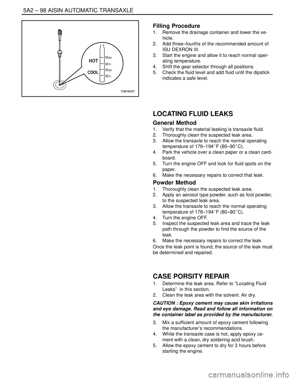
Filling Procedure
1. Remove the drainage container and lower the ve-
hicle.
2. Add three–fourths of the recommended amount of
ISU DEXRON III.
3. Start the engine and allow it to reach normal oper-
ating temperature.
4. Shift the gear selector through all positions.
5. Check the fluid level and add fluid until the dipstick
indicates a safe level.
LOCATING FLUID LEAKS
General Method
1. Verify that the material leaking is transaxle fluid.
2. Thoroughly clean the suspected leak area.
3. Allow the transaxle to reach the normal operating
temperature of 176–194°F (80–90°C).
4. Park the vehicle over a clean paper or a clean card-
board.
5. Turn the engine OFF and look for fluid spots on the
paper.
6. Make the necessary repairs to correct that leak.
Powder Method
1. Thoroughly clean the suspected leak area.
2. Apply an aerosol type powder, such as foot powder,
to the suspected leak area.
3. Allow the transaxle to reach the normal operating
temperature of 176–194°F (80–90°C).
4. Turn the engine OFF.
5. Inspect the suspected leak area and trace the leak
path through the powder to find the source of the
leak.
6. Make the necessary repairs to correct the leak.
Once the leak point is found, the source of the leak must
be determined and repaired.
CASE PORSITY REPAIR
1. Determine the leak area. Refer to ”Locating Fluid
Leaks” in this section.
2. Clean the leak area with the solvent. Air dry.
CAUTION : Epoxy cement may cause skin irritations
and eye damage. Read and follow all information on
the container label as provided by the manufacturer.
3. Mix a sufficient amount of epoxy cement following
the manufacturer’s recommendations.
4. While the transaxle case is hot, apply epoxy ce-
ment with a clean, dry soldering acid brush.
5. Allow the epoxy cement to dry for 3 hours before
starting the engine.
Page 1808 of 2643
5A2 – 218IAISIN AUTOMATIC TRANSAXLE
DAEWOO V–121 BL4
GENERAL DESCRIPTION
AND SYSTEM OPERATION
TRANSAXLE DESCRIPTION
The new automatic transmission is an electronically con-
trolled 4–speed automatic transmission with Lock–up
mechanism.
The transmission is mainly composed of the torque con-
verter with lock up clutch, newly developed 4–speed plan-
etary gear unit, the hydraulic control system and the elec-
tric control system.
ELECTRONICAL COMPONENTS
Transmission Control Module (TCM)
The TCM primarily controls shift points and lockup en-
gagement. It is located on the driver side under the instru-
ment panel.
The transmission is controlled by an electronic shift sys-
tem. The Transmission Control Module (TCM) processes
input signals. From the information received, the TCM
controls the transmission hydraulic system.
The electronic shift system consists of the following :
S Transmission control module (TCM)
S Shift solenoids (SS1 and SS2)
S Pressure control solenoid (PCS)
S Lockup solenoid
S Input shaft speed (ISS) sensor
S Output shaft speed (OSS) sensor
S Transmission Fluid Temperature (TFT) sensor
S Transmission Range (TR) Switch
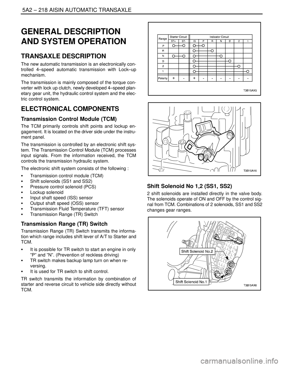
Transmission Range (TR) Switch
Transmission Range (TR) Switch transmits the informa-
tion which range includes shift lever of A/T to Starter and
TCM.
S It is possible for TR switch to start an engine in only
”P” and ”N”. (Prevention of reckless driving)
S TR switch makes backup lamp turn on when re-
versing.
S It is used for TR switch to shift control.
TR switch transmits the information by combination of
starter and reverse circuit to vehicle side directly without
TCM.
Shift Solenoid No 1,2 (SS1, SS2)
2 shift solenoids are installed directly in the valve body.
The solenoids operate of ON and OFF by the control sig-
nal from TCM. Combinations of 2 solenoids, SS1 and SS2
changes gear ranges.
Page 1809 of 2643
AISIN AUTOMATIC TRANSAXLE 5A2 – 219
DAEWOO V–121 BL4
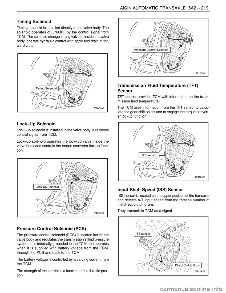
Timing Solenoid
Timing solenoid is installed directly in the valve body. The
solenoid operates of ON/OFF by the control signal from
TCM. The solenoid change timing valve of inside the valve
body, operate hydraulic control with apply and drain of for-
ward clutch.
Lock–Up Solenoid
Lock–up solenoid is installed in the valve body. It recieves
control signal from TCM.
Lock–up solenoid operates the lock–up valve inside the
valve body and controls the torque converter lockup func-
tion.
Pressure Control Solenoid (PCS)
The pressure control solenoid (PCS) is located inside the
valve body and regulates the transmission’s fluid pressure
system. It is internally grounded in the TCM and operates
when it is supplied with battery voltage from the TCM,
through the PCS and back to the TCM.
The battery voltage is controlled by a varying current from
the TCM.
The strength of the current is a function of the throttle posi-
tion.
Transmission Fluid Temperature (TFT)
Sensor
TFT sensor provides TCM with information on the trans-
mission fluid temperature.
The TCM uses information from the TFT sensor to calcu-
late the gear shift points and to engage the torque convert-
er lockup function.
Input Shaft Speed (ISS) Sensor
ISS sensor is located on the upper position of the transaxle
and detects A/T input speed from the rotation number of
the direct clutch drum.
They transmit to TCM as a signal.
Page 1810 of 2643
5A2 – 220IAISIN AUTOMATIC TRANSAXLE
DAEWOO V–121 BL4
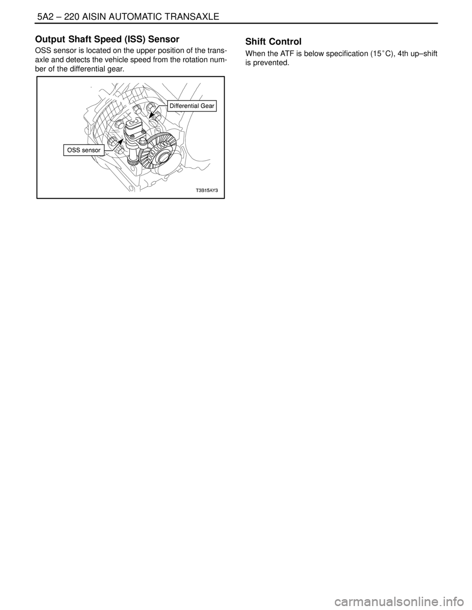
Output Shaft Speed (ISS) Sensor
OSS sensor is located on the upper position of the trans-
axle and detects the vehicle speed from the rotation num-
ber of the differential gear.
Shift Control
When the ATF is below specification (15°C), 4th up–shift
is prevented.
Page 1815 of 2643
AISIN AUTOMATIC TRANSAXLE 5A2 – 225
DAEWOO V–121 BL4
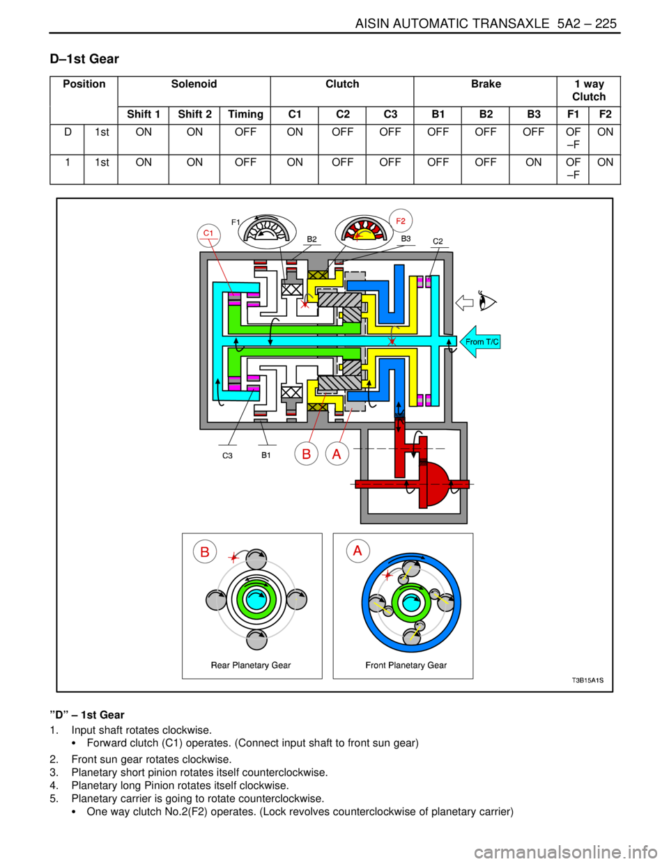
D–1st Gear
PositionSolenoidClutchBrake1 way
Clutch
Shift 1Shift 2TimingC1C2C3B1B2B3F1F2
D1stONONOFFONOFFOFFOFFOFFOFFOF
–FON
11stONONOFFONOFFOFFOFFOFFONOF
–FON
”D” – 1st Gear
1. Input shaft rotates clockwise.
S Forward clutch (C1) operates. (Connect input shaft to front sun gear)
2. Front sun gear rotates clockwise.
3. Planetary short pinion rotates itself counterclockwise.
4. Planetary long Pinion rotates itself clockwise.
5. Planetary carrier is going to rotate counterclockwise.
S One way clutch No.2(F2) operates. (Lock revolves counterclockwise of planetary carrier)
Page 1817 of 2643
AISIN AUTOMATIC TRANSAXLE 5A2 – 227
DAEWOO V–121 BL4
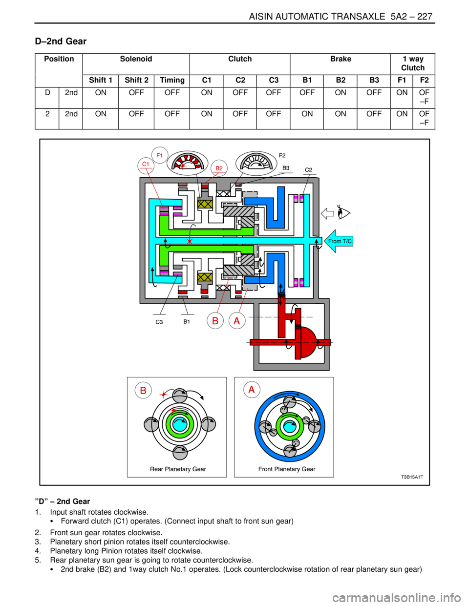
D–2nd Gear
PositionSolenoidClutchBrake1 way
Clutch
Shift 1Shift 2TimingC1C2C3B1B2B3F1F2
D2ndONOFFOFFONOFFOFFOFFONOFFONOF
–F
22ndONOFFOFFONOFFOFFONONOFFONOF
–F
”D” – 2nd Gear
1. Input shaft rotates clockwise.
S Forward clutch (C1) operates. (Connect input shaft to front sun gear)
2. Front sun gear rotates clockwise.
3. Planetary short pinion rotates itself counterclockwise.
4. Planetary long Pinion rotates itself clockwise.
5. Rear planetary sun gear is going to rotate counterclockwise.
S 2nd brake (B2) and 1way clutch No.1 operates. (Lock counterclockwise rotation of rear planetary sun gear)
Page 1819 of 2643
AISIN AUTOMATIC TRANSAXLE 5A2 – 229
DAEWOO V–121 BL4
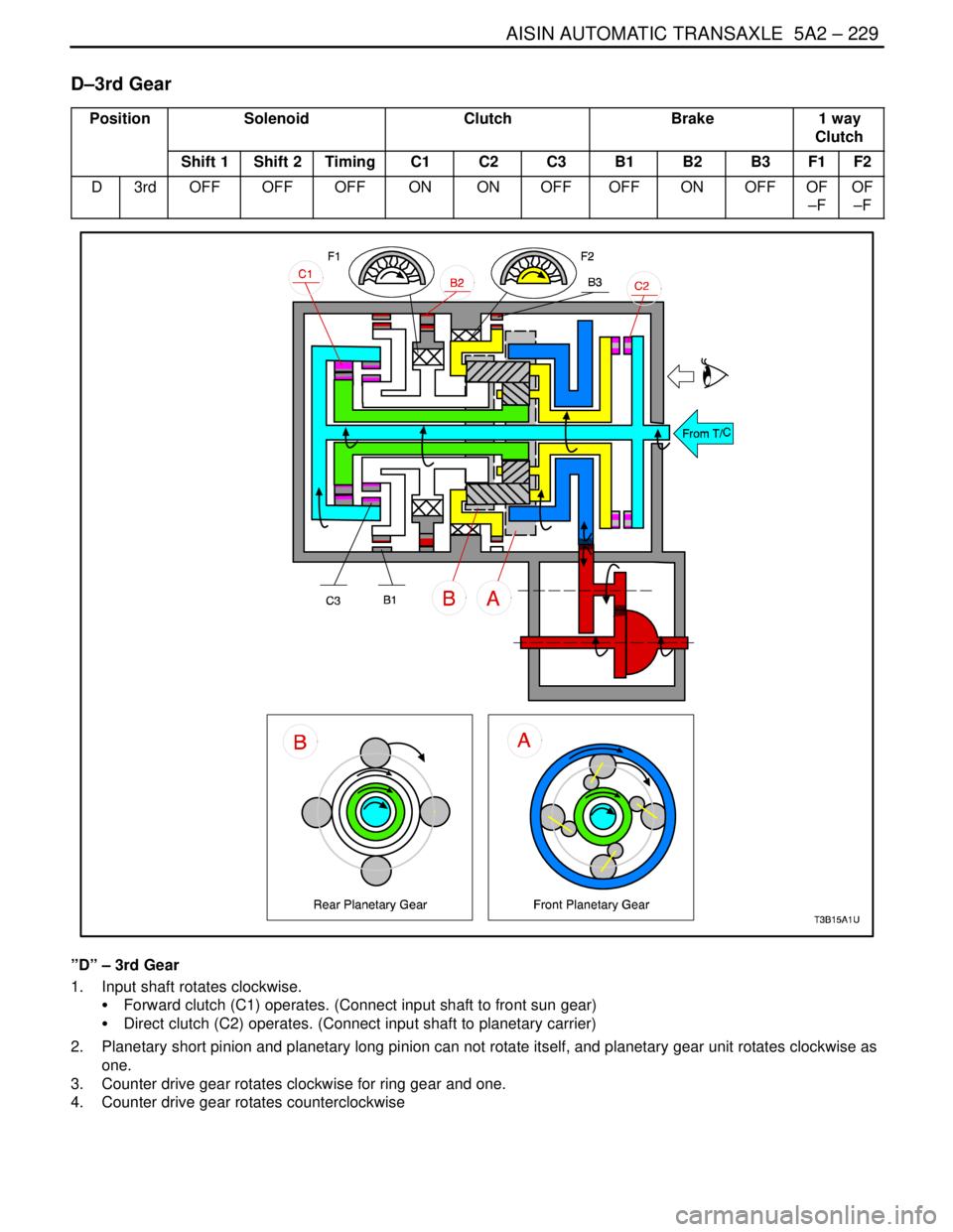
D–3rd Gear
PositionSolenoidClutchBrake1 way
Clutch
Shift 1Shift 2TimingC1C2C3B1B2B3F1F2
D3rdOFFOFFOFFONONOFFOFFONOFFOF
–FOF
–F
”D” – 3rd Gear
1. Input shaft rotates clockwise.
S Forward clutch (C1) operates. (Connect input shaft to front sun gear)
S Direct clutch (C2) operates. (Connect input shaft to planetary carrier)
2. Planetary short pinion and planetary long pinion can not rotate itself, and planetary gear unit rotates clockwise as
one.
3. Counter drive gear rotates clockwise for ring gear and one.
4. Counter drive gear rotates counterclockwise