Crankshaft position sensor DAEWOO NUBIRA 2004 Service Repair Manual
[x] Cancel search | Manufacturer: DAEWOO, Model Year: 2004, Model line: NUBIRA, Model: DAEWOO NUBIRA 2004Pages: 2643, PDF Size: 80.54 MB
Page 33 of 2643

SECTION : 1A
GENERAL ENGINE INFORMATION
TABLE OF CONTENTS
DIAGNOSIS1A–1 . . . . . . . . . . . . . . . . . . . . . . . . . . . . . . . .
Compression Test 1A–1. . . . . . . . . . . . . . . . . . . . . . . . .
Oil Pressure Test 1A–2. . . . . . . . . . . . . . . . . . . . . . . . . .
Oil Leak Diagnosis 1A–3. . . . . . . . . . . . . . . . . . . . . . . .
Knock Diagnosis 1A–4. . . . . . . . . . . . . . . . . . . . . . . . . . Noise Diagnosis 1A–8. . . . . . . . . . . . . . . . . . . . . . . . . .
GENERAL INFORMATION1A–11 . . . . . . . . . . . . . . . . . .
Cleanliness and Care 1A–11. . . . . . . . . . . . . . . . . . . . .
On–Engine Service 1A–11. . . . . . . . . . . . . . . . . . . . . . .
DIAGNOSIS
COMPRESSION TEST
Important : Disconnect the Crankshaft Position (CKP)
Sensor connector to disable the fuel and the ignition sys-
tems.
Test the compression pressure for each cylinder. Low
compression pressure may be the fault of the valves or the
pistons. The following conditions should be considered
when you check the cylinder compression:
S The engine should be at normal operating tempera-
ture.
S The throttle must be wide open.
S All the spark plugs should be removed.
S The battery must be at or near full charge.
1. Place approximately three squirts of oil from a
plunger– type oiler into each spark plug port.
2. Insert the engine compression gauge into each
spark plug port.
3. Crank test each cylinder with four to five compres-
sion strokes using the starter motor.4. The lowest reading should not be less than 70% of
the highest reading. The compression gauge read-
ing should not be less than 689 kPa (100 psi) for
any of the cylinders.
5. Examine the gauge readings obtained after the four
”puffs” per cylinder are obtained from cranking the
starter motor. The readings are explained in the
following descriptions:
S Normal Condition – Compression builds up quickly
and evenly to the specified compression on each
cylinder.
S Piston Rings Faulty – Compression is low on the
first stroke and tends to build up on following
strokes, but the compression pressure does not
reach normal. The compression pressure improves
considerably with the addition of oil into the cylin-
der.
S Valves Faulty – Low compression pressure on the
first stroke. The compression pressure does not
tend to build up on the following strokes. The com-
pression pressure does not improve much with the
addition of oil into the cylinder.
Page 56 of 2643
1.4L/1.6L DOHC ENGINE MECHANICAL 1C1 – 13
DAEWOO V–121 BL4
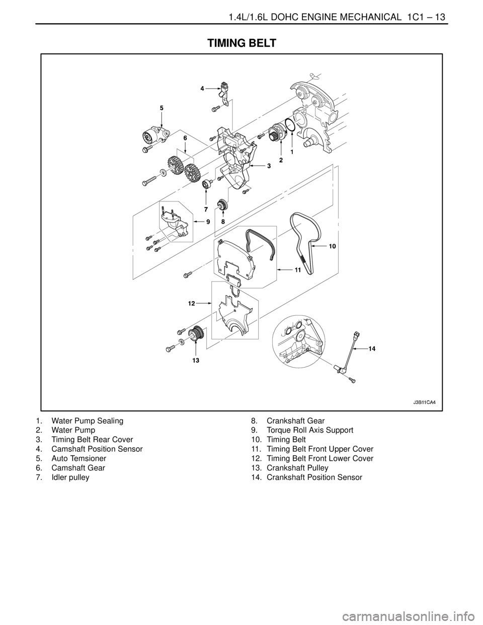
TIMING BELT
1. Water Pump Sealing
2. Water Pump
3. Timing Belt Rear Cover
4. Camshaft Position Sensor
5. Auto Temsioner
6. Camshaft Gear
7. Idler pulley8. Crankshaft Gear
9. Torque Roll Axis Support
10. Timing Belt
11. Timing Belt Front Upper Cover
12. Timing Belt Front Lower Cover
13. Crankshaft Pulley
14. Crankshaft Position Sensor
Page 93 of 2643
1C1 – 50I1.4L/1.6L DOHC ENGINE MECHANICAL
DAEWOO V–121 BL4
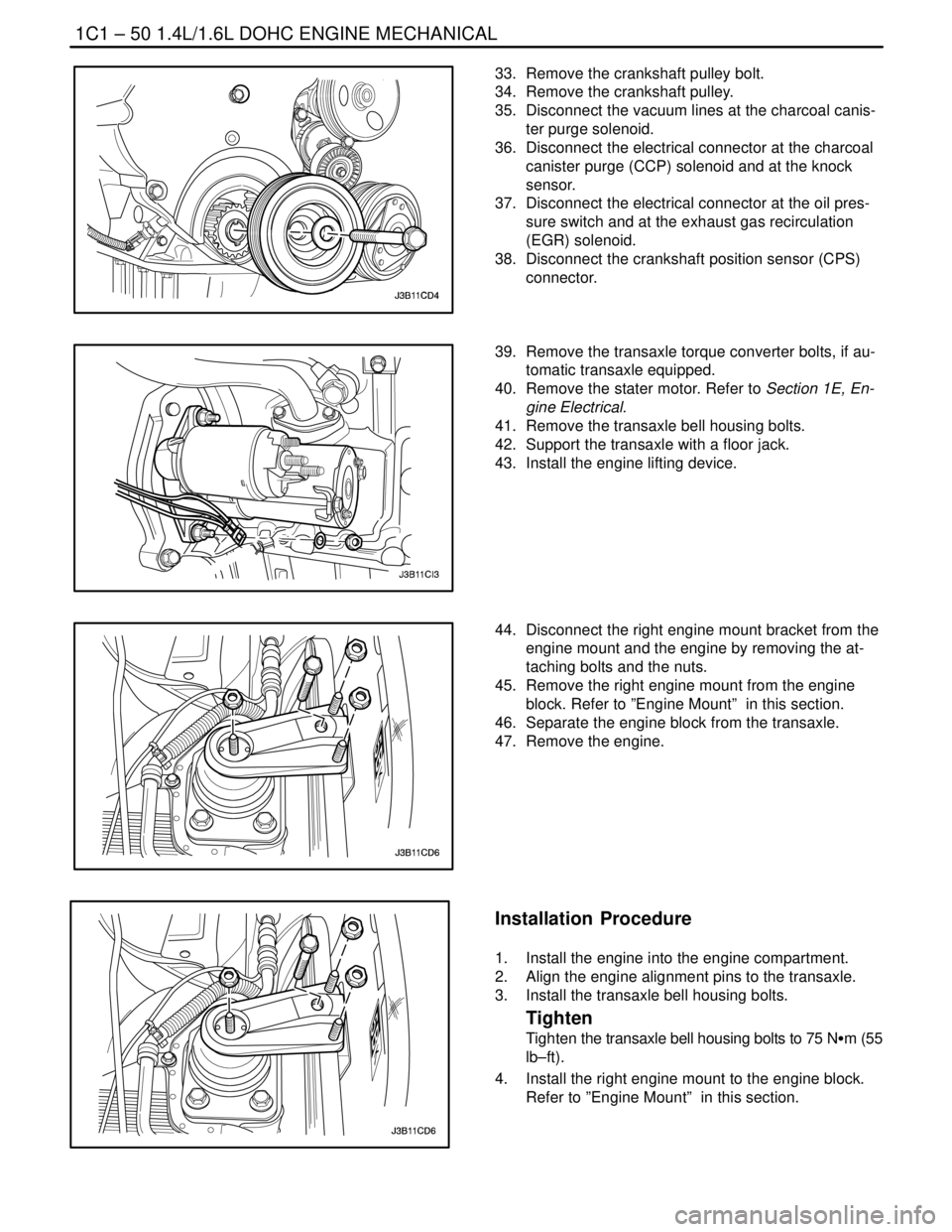
33. Remove the crankshaft pulley bolt.
34. Remove the crankshaft pulley.
35. Disconnect the vacuum lines at the charcoal canis-
ter purge solenoid.
36. Disconnect the electrical connector at the charcoal
canister purge (CCP) solenoid and at the knock
sensor.
37. Disconnect the electrical connector at the oil pres-
sure switch and at the exhaust gas recirculation
(EGR) solenoid.
38. Disconnect the crankshaft position sensor (CPS)
connector.
39. Remove the transaxle torque converter bolts, if au-
tomatic transaxle equipped.
40. Remove the stater motor. Refer to Section 1E, En-
gine Electrical.
41. Remove the transaxle bell housing bolts.
42. Support the transaxle with a floor jack.
43. Install the engine lifting device.
44. Disconnect the right engine mount bracket from the
engine mount and the engine by removing the at-
taching bolts and the nuts.
45. Remove the right engine mount from the engine
block. Refer to ”Engine Mount” in this section.
46. Separate the engine block from the transaxle.
47. Remove the engine.
Installation Procedure
1. Install the engine into the engine compartment.
2. Align the engine alignment pins to the transaxle.
3. Install the transaxle bell housing bolts.
Tighten
Tighten the transaxle bell housing bolts to 75 NSm (55
lb–ft).
4. Install the right engine mount to the engine block.
Refer to ”Engine Mount” in this section.
Page 131 of 2643

1.8L DOHC ENGINE MECHANICAL 1C2 – 11
DAEWOO V–121 BL4
1. Connecting Rod
2. Bearing Set
3. Connecting Rod Bolt
4. Piston Ring Set
5. Piston Pin
6. Piston
7. Engine Block
8. Sleeve
9. Water Jacket Cap
10. Bolt (Manual Transaxle)
11. Flywheel (Manual Transaxle)
12. Flexible Plate (Automatic Transaxle)
13. Bolt (Automatic Transaxle)
14. Clamp
15. Hose
16. Clamp
17. Engine Ventilation Pipe
18. Bolt
19. Gasket
20. Needle Sleeve
21. Crankshaft Rear Seal
22. Crankshaft
23. Transmitter Disk
24. Bolt
25. Oil Pan Scraper
26. Oil Pan
27. Drain Plug
28. Washer
29. Bolt
30. Sleeve
31. Gasket
32. Bolt
33. Oil Pump Cover
34. Ring Gear
35. Gear
36. Oil Pressure Switch
37. Washer
38. Washer
39. Oil Duct Outlet Plug
40. Connecting Piece
41. Seal Ring
42. Oil Filter43. Bypass Valve
44. Pressure Relief Valve Plunger
45. Pressure Relief Valve Spring
46. Seal Ring
47. Pressure Relief Valve Plug
48. Seal Ring
49. Bolt
50. Oil Suction Pipe
51. Bolt
52. Rear Timing Belt Cover
53. Bolt
54. Special Bolt
55. Idler Pulley
56. Stud
57. Nut
58. Bolt
59. Tensioner
60. Bolt
61. Thrust Inner Washer
62. Woodruff Key
63. Crankshaft Gear
64. Thrust Outer Washer
65. Bolt
66. Camshaft Drive Belt
67. Gasket
68. Front Timing Belt Cover
69. Bolt
70. Bushing Plug
71. Bushing
72. Oil Gallery Plug
73. Bolt
74. Water Pump
75. Seal Ring
76. Crankshaft Position Sensor
77. Bolt
78. Knock Sensor*
79. Bolt
80. Bolt
81. Crankshaft Bearing Bridge
* : 2.0L DOHC Engine
Page 134 of 2643
1C2 – 14I1.8L DOHC ENGINE MECHANICAL
DAEWOO V–121 BL4
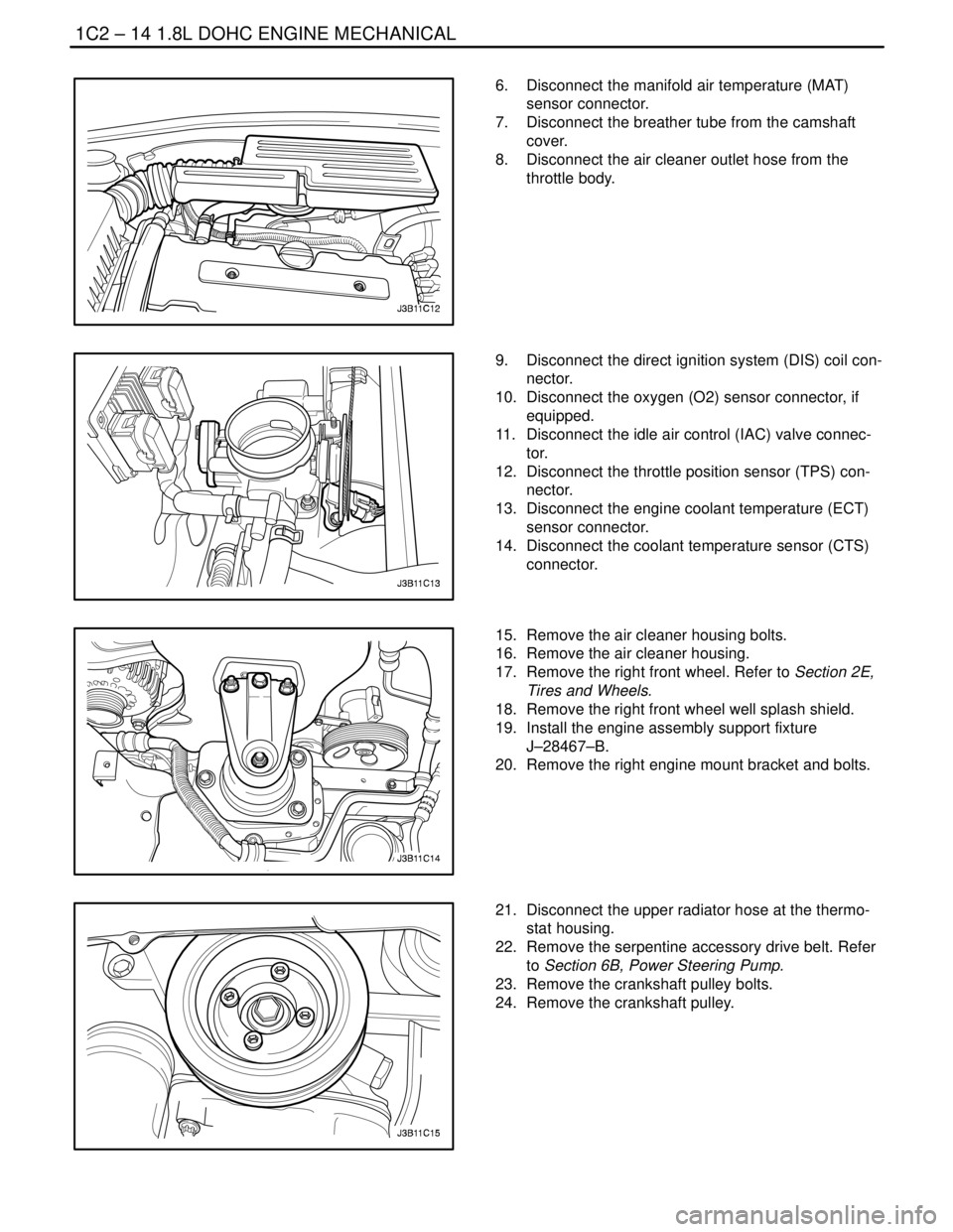
6. Disconnect the manifold air temperature (MAT)
sensor connector.
7. Disconnect the breather tube from the camshaft
cover.
8. Disconnect the air cleaner outlet hose from the
throttle body.
9. Disconnect the direct ignition system (DIS) coil con-
nector.
10. Disconnect the oxygen (O2) sensor connector, if
equipped.
11. Disconnect the idle air control (IAC) valve connec-
tor.
12. Disconnect the throttle position sensor (TPS) con-
nector.
13. Disconnect the engine coolant temperature (ECT)
sensor connector.
14. Disconnect the coolant temperature sensor (CTS)
connector.
15. Remove the air cleaner housing bolts.
16. Remove the air cleaner housing.
17. Remove the right front wheel. Refer to Section 2E,
Tires and Wheels.
18. Remove the right front wheel well splash shield.
19. Install the engine assembly support fixture
J–28467–B.
20. Remove the right engine mount bracket and bolts.
21. Disconnect the upper radiator hose at the thermo-
stat housing.
22. Remove the serpentine accessory drive belt. Refer
to Section 6B, Power Steering Pump.
23. Remove the crankshaft pulley bolts.
24. Remove the crankshaft pulley.
Page 168 of 2643
1C2 – 48I1.8L DOHC ENGINE MECHANICAL
DAEWOO V–121 BL4
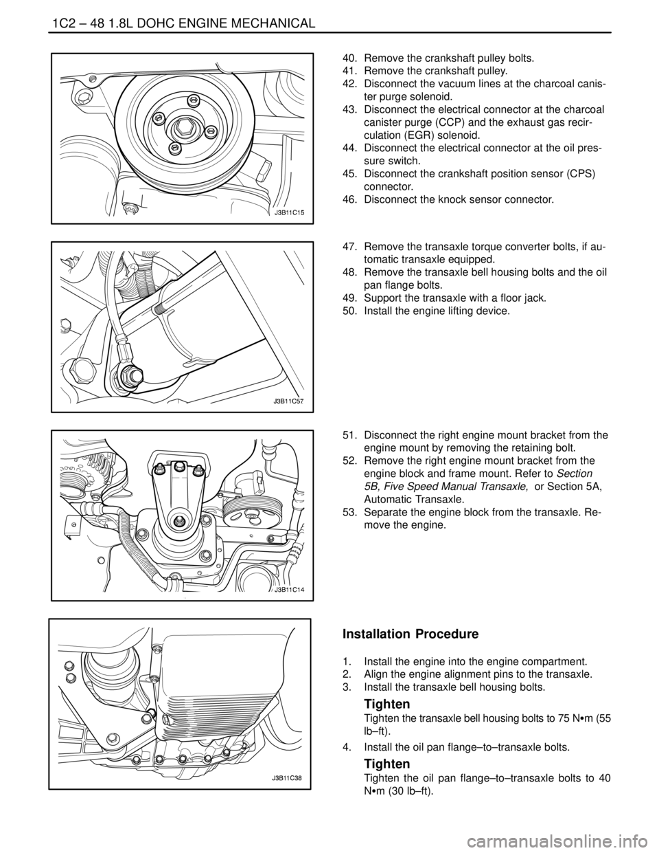
40. Remove the crankshaft pulley bolts.
41. Remove the crankshaft pulley.
42. Disconnect the vacuum lines at the charcoal canis-
ter purge solenoid.
43. Disconnect the electrical connector at the charcoal
canister purge (CCP) and the exhaust gas recir-
culation (EGR) solenoid.
44. Disconnect the electrical connector at the oil pres-
sure switch.
45. Disconnect the crankshaft position sensor (CPS)
connector.
46. Disconnect the knock sensor connector.
47. Remove the transaxle torque converter bolts, if au-
tomatic transaxle equipped.
48. Remove the transaxle bell housing bolts and the oil
pan flange bolts.
49. Support the transaxle with a floor jack.
50. Install the engine lifting device.
51. Disconnect the right engine mount bracket from the
engine mount by removing the retaining bolt.
52. Remove the right engine mount bracket from the
engine block and frame mount. Refer to Section
5B, Five Speed Manual Transaxle, or Section 5A,
Automatic Transaxle.
53. Separate the engine block from the transaxle. Re-
move the engine.
Installation Procedure
1. Install the engine into the engine compartment.
2. Align the engine alignment pins to the transaxle.
3. Install the transaxle bell housing bolts.
Tighten
Tighten the transaxle bell housing bolts to 75 NSm (55
lb–ft).
4. Install the oil pan flange–to–transaxle bolts.
Tighten
Tighten the oil pan flange–to–transaxle bolts to 40
NSm (30 lb–ft).
Page 248 of 2643

1F – 2IENGINE CONTROLS
DAEWOO V–121 BL4
TROUBLE CODE DIAGNOSIS
(1.4L/1.6L DOHC) 1F–111. . . . . . . . . . . . . . . . . . . . . . . .
Clearing Trouble Codes 1F–111. . . . . . . . . . . . . . . . . . . .
Diagnostic Trouble Codes (1.4L/1.6L DOHC) 1F–111.
DTC P0107 Manifold Absolute Pressure Sensor
Low Voltage 1F–114. . . . . . . . . . . . . . . . . . . . . . . . . . .
DTC P0108 Manifold Absolute Pressure Sensor
High Voltage 1F–117. . . . . . . . . . . . . . . . . . . . . . . . . .
DTC P0112 Intake Air Temperature Sensor Low
Voltage 1F–120. . . . . . . . . . . . . . . . . . . . . . . . . . . . . . .
DTC P0113 Intake Air Temperature Sensor High
Voltage 1F–122. . . . . . . . . . . . . . . . . . . . . . . . . . . . . . .
DTC P0117 Engine Coolant Temperature
Sensor Low Voltage 1F–125. . . . . . . . . . . . . . . . . . . .
DTC P0118 Engine Coolant Temperature
Sensor High Voltage 1F–128. . . . . . . . . . . . . . . . . . . .
DTC P0122 Throttle Position Sensor Low
Voltage 1F–131. . . . . . . . . . . . . . . . . . . . . . . . . . . . . . .
DTC P0123 Throttle Position Sensor High
Voltage 1F–134. . . . . . . . . . . . . . . . . . . . . . . . . . . . . . .
DTC P0131 Front Heated Oxygen Sensor Low
Voltage 1F–137. . . . . . . . . . . . . . . . . . . . . . . . . . . . . . .
DTC P0132 Front Heated Oxygen Sensor High
Voltage 1F–140. . . . . . . . . . . . . . . . . . . . . . . . . . . . . . .
DTC P0133 Front Heated Oxygen Sensor No
Activity 1F–142. . . . . . . . . . . . . . . . . . . . . . . . . . . . . . .
DTC P0135 Front Heated Oxygen Sensor Heater
Circuit Not Functioning 1F–145. . . . . . . . . . . . . . . . . .
DTC P0137 Rear Heated Oxygen Sensor Low
Voltage 1F–148. . . . . . . . . . . . . . . . . . . . . . . . . . . . . . .
DTC P0138 Rear Heated Oxygen Sensor High
Voltage 1F–151. . . . . . . . . . . . . . . . . . . . . . . . . . . . . . .
DTC P0140 Rear Heated Oxygen Sensor No
Activity 1F–153. . . . . . . . . . . . . . . . . . . . . . . . . . . . . . .
DTC P0141 Rear Heated Oxygen Sensor Heater
Malfunction 1F–156. . . . . . . . . . . . . . . . . . . . . . . . . . .
DTC P0171 Fuel Trim System Too Lean 1F–158. . . .
DTC P0172 Fuel Trim System Too Rich 1F–162. . . . .
DTC P0222 Main Throttle Idle Actuator (MTIA)
Low Voltage 1F–165. . . . . . . . . . . . . . . . . . . . . . . . . . .
DTC P0223 Main Throttle Idle Actuator (MTIA)
High Voltage 1F–168. . . . . . . . . . . . . . . . . . . . . . . . . .
DTC P0261 Injector 1 Low Voltage 1F–171. . . . . . . . .
DTC P0262 Injector 1 High Voltage 1F–173. . . . . . . .
DTC P0264 Injector 2 Low Voltage 1F–175. . . . . . . . .
DTC P0265 Injector 2 High Voltage 1F–177. . . . . . . .
DTC P0267 Injector 3 Low Voltage 1F–179. . . . . . . . .
DTC P0268 Injector 3 High Voltage 1F–181. . . . . . . .
DTC P0270 Injector 4 Low Voltage 1F–183. . . . . . . . .
DTC P0271 Injector 4 High Voltage 1F–185. . . . . . . . DTC P0300 Multiple Cylinder Misfire(Catalyst
Damage) 1F–188. . . . . . . . . . . . . . . . . . . . . . . . . . . . .
DTC P0300 Multiple Cylinder Misfire(Increase
Emission) 1F–192. . . . . . . . . . . . . . . . . . . . . . . . . . . . .
DTC P0327 Knock Sensor Circuit Fault
(1.4L DOHC) 1F–195. . . . . . . . . . . . . . . . . . . . . . . . . .
DTC P0327 Knock Sensor Circuit Fault
(1.6L DOHC) 1F–198. . . . . . . . . . . . . . . . . . . . . . . . . .
DTC P0335 Magnetic Crankshaft Position
Sensor Electrical Error 1F–201. . . . . . . . . . . . . . . . . .
DTC P0336 58X Crankshaft Position Sensor
No Plausible Signal 1F–204. . . . . . . . . . . . . . . . . . . .
DTC P0337 58X Crankshaft Position Sensor
No Signal 1F–207. . . . . . . . . . . . . . . . . . . . . . . . . . . . .
DTC P0341 Camshaft Position Sensor
Rationality 1F–210. . . . . . . . . . . . . . . . . . . . . . . . . . . .
DTC P0342 Camshaft Position Sensor Signal 1F–212
DTC P0351 Ignition Signal Coil A Fault 1F–214. . . . .
DTC P0352 Ignition Signal Coil B Fault 1F–216. . . . .
DTC P0400 Exhaust Gas Recirculation Out
Of Limit 1F–218. . . . . . . . . . . . . . . . . . . . . . . . . . . . . . .
DTC P0404 Exhaust Gas Recirculation
Opened 1F–221. . . . . . . . . . . . . . . . . . . . . . . . . . . . . . .
DTC P0405 EGR Pintle Position Sensor Low
Voltage 1F–224. . . . . . . . . . . . . . . . . . . . . . . . . . . . . . .
DTC P0406 EGR Pintle Position Sensor High
Voltage 1F–227. . . . . . . . . . . . . . . . . . . . . . . . . . . . . . .
DTC P0420 Catalyst Low Efficiency 1F–230. . . . . . . .
DTC P0444 EVAP Purge Control Circuit No
Signal 1F–232. . . . . . . . . . . . . . . . . . . . . . . . . . . . . . . .
DTC P0445 EVAP Purge Control Circuit Fault 1F–235
DTC P0462 Fuel Level Sensor Low Voltage
(1.6L DOHC Only) 1F–238. . . . . . . . . . . . . . . . . . . . .
DTC P0463 Fuel Level Sensor High Voltage
(1.6L DOHC Only) 1F–241. . . . . . . . . . . . . . . . . . . . .
DTC P0480 Low Speed Cooling Fan Relay
Circuit Fault (1.4L DOHC) 1F–245. . . . . . . . . . . . . . .
DTC P0480 Low Speed Cooling Fan Relay
Circuit Fault (1.6L DOHC) 1F–248. . . . . . . . . . . . . . .
DTC P0481 High Speed Cooling Fan Relay
Circuit Fault (1.4L DOHC) 1F–251. . . . . . . . . . . . . . .
DTC P0481 High Speed Cooling Fan Relay
Circuit Fault (1.6L DOHC) 1F–254. . . . . . . . . . . . . . .
DTC P0501 Vehicle Speed No Signal
(M/T Only) 1F–257. . . . . . . . . . . . . . . . . . . . . . . . . . . .
DTC P0510 Throttle Position Switch Circuit Fault
(1.4L DOHC) 1F–260. . . . . . . . . . . . . . . . . . . . . . . . . .
DTC P0510 Throttle Position Switch Circuit
Fault (1.6L DOHC) 1F–262. . . . . . . . . . . . . . . . . . . . .
DTC P0532 A/C Pressure Sensor Low Voltage 1F–264
DTC P0533 A/C Pressure Sensor High
Voltage 1F–267. . . . . . . . . . . . . . . . . . . . . . . . . . . . . . .
Page 249 of 2643

ENGINE CONTROLS 1F – 3
DAEWOO V–121 BL4
DTC P0562 System Voltage(Engine Side) Too
Low 1F–270. . . . . . . . . . . . . . . . . . . . . . . . . . . . . . . . . .
DTC P0563 System Voltage(Engine Side) Too
High 1F–272. . . . . . . . . . . . . . . . . . . . . . . . . . . . . . . . . .
DTC P0601 Engine Control Module Checksum
Error 1F–274. . . . . . . . . . . . . . . . . . . . . . . . . . . . . . . . .
DTC P0604 Engine Control Module Internal/External
RAM Error 1F–275. . . . . . . . . . . . . . . . . . . . . . . . . . . .
DTC P0605 Engine Control Module INMVY Write
Error 1F–276. . . . . . . . . . . . . . . . . . . . . . . . . . . . . . . . .
DTC P0656 Fuel Level Gauge Circuit Fault 1F–277. .
DTC P1181 Variable Intake Manifold Solenoid
Low Voltage 1F–279. . . . . . . . . . . . . . . . . . . . . . . . . . .
DTC P1182 Variable Intake Manifold Solenoid
High Voltage 1F–281. . . . . . . . . . . . . . . . . . . . . . . . . .
DTC P1230 Fuel Pump Relay Low Voltage
(1.4L DOHC) 1F–283. . . . . . . . . . . . . . . . . . . . . . . . . .
DTC P1230 Fuel Pump Relay Low Voltage
(1.6L DOHC) 1F–286. . . . . . . . . . . . . . . . . . . . . . . . . .
DTC P1231 Fuel Pump Relay High Voltage
(1.4L DOHC) 1F–289. . . . . . . . . . . . . . . . . . . . . . . . . .
DTC P1231 Fuel Pump Relay High Voltage
(1.6L DOHC) 1F–292. . . . . . . . . . . . . . . . . . . . . . . . . .
DTC P1320 Crankshaft Segment Period
Segment Adaptation At Limit 1F–295. . . . . . . . . . . .
DTC P1321 Crankshaft Segment Period Tooth
Error 1F–297. . . . . . . . . . . . . . . . . . . . . . . . . . . . . . . . .
DTC P1382 Rough Road Data Invalid
(NON ABS) 1F–299. . . . . . . . . . . . . . . . . . . . . . . . . . .
DTC P1382 Rough Road Data Invalid (ABS) 1F–302
DTC P1385 Rough Road Sensor Circuit Fault
(NON ABS) 1F–305. . . . . . . . . . . . . . . . . . . . . . . . . . .
DTC P1402 Exhaust Gas Recirculation
Blocked 1F–308. . . . . . . . . . . . . . . . . . . . . . . . . . . . . . .
DTC P1403 Exhaust Gas Recirculation Valve
Failure 1F–310. . . . . . . . . . . . . . . . . . . . . . . . . . . . . . . .
DTC P1404 Exhaust Gas Recirculation Closed1F–313
DTC P1511 Idle Charge Actuator Circuit Fault 1F–316
DTC P1512 Idle Charge Actuator Mechanical
Error 1F–319. . . . . . . . . . . . . . . . . . . . . . . . . . . . . . . . .
DTC P1513 Idle Charge Actuator Functional
Error 1F–321. . . . . . . . . . . . . . . . . . . . . . . . . . . . . . . . .
DTC P1537 A/C Compressor Relay High
Voltage 1F–324. . . . . . . . . . . . . . . . . . . . . . . . . . . . . . .
DTC P1538 A/C Compressor Relay Low
Voltage 1F–326. . . . . . . . . . . . . . . . . . . . . . . . . . . . . . .
DTC P1610 Main Relay High Voltage
(1.4L DOCH) 1F–328. . . . . . . . . . . . . . . . . . . . . . . . . .
DTC P1610 Main Relay High Voltage
(1.6L DOHC) 1F–330. . . . . . . . . . . . . . . . . . . . . . . . . .
DTC P1611 Main Relay Low Voltage
(1.4L DOHC) 1F–332. . . . . . . . . . . . . . . . . . . . . . . . . . DTC P1611 Main Relay Low Voltage
(1.6L DOHC) 1F–334. . . . . . . . . . . . . . . . . . . . . . . . . .
DTC P1628 Immobilizer No Successful
Communication 1F–336. . . . . . . . . . . . . . . . . . . . . . . .
DTC P1629 Immobilizer Wrong Computation 1F–338
DTC P1660 Malfunction Indicator Lamp (MIL)
High Voltage 1F–340. . . . . . . . . . . . . . . . . . . . . . . . . .
DTC P1661 Malfunction Indicator Lamp (MIL)
Low Voltage 1F–342. . . . . . . . . . . . . . . . . . . . . . . . . . .
TROUBLE CODE DIAGNOSIS (1.8L DOHC) 1F–344.
Clearing Trouble Codes 1F–344. . . . . . . . . . . . . . . . . . .
Diagnostic Trouble Codes (1.8L DOHC) 1F–344. . . .
DTC P0106 Manifold Absolute Pressure
Rationality 1F–347. . . . . . . . . . . . . . . . . . . . . . . . . . . .
DTC P0107 Manifold Absolut Pressure Low
Voltage 1F–349. . . . . . . . . . . . . . . . . . . . . . . . . . . . . . .
DTC P0108 Manifold Absolut Pressure High
Voltage 1F–352. . . . . . . . . . . . . . . . . . . . . . . . . . . . . . .
DTC P0112 Intake Air Temperature Low
Voltage 1F–355. . . . . . . . . . . . . . . . . . . . . . . . . . . . . . .
DTC P0113 Intake Air Temperature High
Voltage 1F–358. . . . . . . . . . . . . . . . . . . . . . . . . . . . . . .
DTC P0117 Engine Coolant Temperature Low
Voltage 1F–361. . . . . . . . . . . . . . . . . . . . . . . . . . . . . . .
DTC P0118 Engine Coolant Temperature High
Voltage 1F–363. . . . . . . . . . . . . . . . . . . . . . . . . . . . . . .
DTC P0122 Throttle Position Sensor Low
Voltage 1F–366. . . . . . . . . . . . . . . . . . . . . . . . . . . . . . .
DTC P0123 Throttle Position Sensor High
Voltage 1F–369. . . . . . . . . . . . . . . . . . . . . . . . . . . . . . .
DTC P0131 Front Heated Oxygen Sensor
(HO2S1) Low Voltage 1F–372. . . . . . . . . . . . . . . . . .
DTC P0132 Front Heated Oxygen Sensor
(HO2S1) High Voltage 1F–375. . . . . . . . . . . . . . . . . .
DTC P0133 Front Heated Oxygen Sensor
(HO2S1) Slow Response 1F–378. . . . . . . . . . . . . . .
DTC P0134 Front Heated Oxygen Sensor
(HO2S1) No Activity or Open 1F–382. . . . . . . . . . . .
DTC P0135 Front Heated Oxygen Sensor
(HO2S1) Heater Circuit Not Functioning 1F–385. . .
DTC P0137 Rear Heated Oxygen Sensor
(HO2S2) Low Voltage 1F–388. . . . . . . . . . . . . . . . . .
DTC P0138 Rear Heated Oxygen Sensor
(HO2S2) High Voltage 1F–391. . . . . . . . . . . . . . . . . .
DTC P0140 Rear Heated Oxygen Sensor
(HO2S2) No Activity or Open 1F–394. . . . . . . . . . . .
DTC P0141 Rear Heated Oxygen Sensor
(HO2S2) Heater Circuit Not Functioning 1F–397. . .
DTC P0171 Fuel Trim System Too Lean 1F–400. . . .
DTC P0172 Fuel Trim System Too Rich 1F–404. . . . .
DTC P0201 Injector 1 Circuit Fault 1F–408. . . . . . . . .
DTC P0202 Injector 2 Circuit Fault 1F–411. . . . . . . . .
Page 251 of 2643

ENGINE CONTROLS 1F – 5
DAEWOO V–121 BL4
SYMPTOM DIAGNOSIS1F–574 . . . . . . . . . . . . . . . . . . .
Important Preliminary Checks 1F–574. . . . . . . . . . . . .
Intermittents 1F–574. . . . . . . . . . . . . . . . . . . . . . . . . . . .
Hard Start 1F–576. . . . . . . . . . . . . . . . . . . . . . . . . . . . . .
Surges or Chuggles 1F–579. . . . . . . . . . . . . . . . . . . . . .
Lack of Power, Sluggishness, or Sponginess 1F–581
Hesitation, Sag, Stumble 1F–583. . . . . . . . . . . . . . . . .
Cuts Out, Misses 1F–584. . . . . . . . . . . . . . . . . . . . . . . .
Poor Fuel Economy 1F–587. . . . . . . . . . . . . . . . . . . . . .
Rough, Unstable, or Incorrect Idle, Stalling 1F–588. .
Excessive Exhaust Emissions or Odors 1F–591. . . . .
Dieseling, Run–On 1F–592. . . . . . . . . . . . . . . . . . . . . . .
Backfire 1F–593. . . . . . . . . . . . . . . . . . . . . . . . . . . . . . . .
MAINTENANCE AND REPAIR1F–594 . . . . . . . . . . . . .
ON–VEHICLE SERVICE 1F–594. . . . . . . . . . . . . . . . . . .
Fuel System Pressure Relief 1F–594. . . . . . . . . . . . . .
Fuel Tank 1F–594. . . . . . . . . . . . . . . . . . . . . . . . . . . . . . .
Fuel Pump 1F–596. . . . . . . . . . . . . . . . . . . . . . . . . . . . . .
Fuel Filter 1F–597. . . . . . . . . . . . . . . . . . . . . . . . . . . . . .
Fuel Rail and Injectors (1.4L/1.6L DOHC) 1F–598. . .
Fuel Rail and Injectors (1.8L DOHC) 1F–600. . . . . . .
Engine Coolant Temperature Sensor
(1.4L/1.6L DOHC) 1F–602. . . . . . . . . . . . . . . . . . . . . .
Engine Coolant Temperature Sensor
(1.8L DOHC) 1F–602. . . . . . . . . . . . . . . . . . . . . . . . . .
Throttle Position Sensor (1.8L DOHC) 1F–603. . . . . .
Throttle Body (1.4L/1.6L DOHC) 1F–603. . . . . . . . . . .
Throttle Body (1.8L DOHC) 1F–604. . . . . . . . . . . . . . .
Front Heated Oxygen Sensor (HO2S 1)
(1.4L/1.6L DOHC) 1F–606. . . . . . . . . . . . . . . . . . . . . .
Front Heated Oxygen Sensor (HO2S 1)
(1.8L DOHC) 1F–607. . . . . . . . . . . . . . . . . . . . . . . . . .
Rear Heated Oxygen Sensor (HO2S 2) 1F–607. . . . .
Intake Air Temperature Sensor
(1.4L/1.6L DOHC) 1F–608. . . . . . . . . . . . . . . . . . . . . .
Intake Air Temperature Sensor (1.8L DOHC) 1F–609
Idle Air Control Valve (1.8L DOHC) 1F–609. . . . . . . . .
Manifold Absolute Pressure Sensor
(1.4L/1.6L DOHC) 1F–610. . . . . . . . . . . . . . . . . . . . . .
Manifold Absolute Pressure Sensor
(1.8L DOHC) 1F–611. . . . . . . . . . . . . . . . . . . . . . . . . .
Exhaust Gas Recirculation Valve
(1.4L/1.6L DOHC) 1F–611. . . . . . . . . . . . . . . . . . . . . .
Exhaust Gas Recirculation Valve (1.8L DOHC) 1F–612
Knock Sensor (1.4L/1.6L DOHC) 1F–612. . . . . . . . . .
Knock Sensor (1.8L DOHC) 1F–613. . . . . . . . . . . . . . .
Evaporative Emission Canister 1F–614. . . . . . . . . . . . Evaporative Emission Canister Purge Solenoid Valve 1
F–615
Crankshaft Position (CKP) Sensor
(1.4L/1.6L DOHC) 1F–615. . . . . . . . . . . . . . . . . . . . . .
Crankshaft Position (CKP) Sensor
(1.8L DOHC) 1F–616. . . . . . . . . . . . . . . . . . . . . . . . . .
Camshaft Position Sensor (1.4L/1.6L DOHC) 1F–618
Camshaft Position Sensor (1.8L DOHC) 1F–619. . . .
Engine Control Module (1.4L/1.6L DOHC) 1F–620. . .
Engine Control Module (1.8L DOHC) 1F–621. . . . . . .
Electronic Ignition System Ignition Coil
(1.4L/1.6L DOHC) 1F–621. . . . . . . . . . . . . . . . . . . . . .
Electronic Ignition System Ignition Coil
(1.8L DOHC) 1F–622. . . . . . . . . . . . . . . . . . . . . . . . . .
GENERAL DESCRIPTION AND SYSTEM
OPERATION1F–623 . . . . . . . . . . . . . . . . . . . . . . . . . . . .
Ignition System Operation 1F–623. . . . . . . . . . . . . . . .
Electronic Ignition System Ignition Coil 1F–623. . . . . .
Crankshaft Position Sensor 1F–623. . . . . . . . . . . . . . .
Camshaft Position Sensor 1F–623. . . . . . . . . . . . . . . .
Idle Air System Operation 1F–623. . . . . . . . . . . . . . . . .
Fuel Control System Operation 1F–623. . . . . . . . . . . .
Evaporative Emission Control System
Operation 1F–624. . . . . . . . . . . . . . . . . . . . . . . . . . . . .
Evaporative Emission Canister 1F–625. . . . . . . . . . . .
Positive Crankcase Ventilation System
Operation 1F–625. . . . . . . . . . . . . . . . . . . . . . . . . . . . .
Engine Coolant Temperature Sensor 1F–625. . . . . . .
Throttle Position Sensor 1F–625. . . . . . . . . . . . . . . . . .
Catalyst Monitor Oxygen Sensors 1F–625. . . . . . . . . .
Exhaust Gas Recirculation Valve 1F–626. . . . . . . . . . .
Intake Air Temperature Sensor 1F–626. . . . . . . . . . . .
Idle Air Control Valve 1F–626. . . . . . . . . . . . . . . . . . . . .
Manifold Absolute Pressure Sensor 1F–626. . . . . . . .
Engine Control Module 1F–627. . . . . . . . . . . . . . . . . . .
Fuel Injector 1F–627. . . . . . . . . . . . . . . . . . . . . . . . . . . .
Knock Sensor 1F–627. . . . . . . . . . . . . . . . . . . . . . . . . . .
Rough Road Sensor 1F–627. . . . . . . . . . . . . . . . . . . . .
Strategy–Based Diagnostics 1F–628. . . . . . . . . . . . . .
EOBD Serviceability Issues 1F–628. . . . . . . . . . . . . . .
Serial Data Communications 1F–629. . . . . . . . . . . . . .
On–Board Diagnostic (EOBD) 1F–629. . . . . . . . . . . . .
Comprehensive Component Monitor Diagnostic
Operation 1F–630. . . . . . . . . . . . . . . . . . . . . . . . . . . . .
Common EOBD Terms 1F–630. . . . . . . . . . . . . . . . . . .
Reading Diagnostic Trouble Codes 1F–632. . . . . . . . .
Primary System–Based Diagnostics 1F–633. . . . . . . .
Page 256 of 2643

1F – 10IENGINE CONTROLS
DAEWOO V–121 BL4
FASTENER TIGHTENING SPECIFICATIONS
ApplicationNSmLb–FtLb–In
Camshaft Position Sensor Bolts (1.4L/1.6L DOHC)7–62
Camshaft Position Sensor Bolts (1.8 DOHC)8–71
Crankshaft Position Sensor Retaining Bolt (1.4L/1.6L DOHC)6.5–58
Crankshaft Position Sensor Retaining Bolt (1.8 DOHC)8–71
Electronic Ignition System Ignition Coil Retaining Bolts10–89
Exhaust Gas Recirculation Valve Retaining Bolts3022–
Engine Control Module Bolts12–106
Engine Coolant Temperature Sensor Bolt (1.4L/1.6L DOHC)17.513–
Engine Coolant Temperature Sensor Bolt (1.8 DOHC)2015–
Evaporative Emission Canister Flange Bolt4–35
Evaporative Emission Canister Purge Solenoid Bracket Bolt5–44
Fuel Filter Mounting Bracket Assembly Bolt4–35
Fuel Tank Retaining Bolts2015–
Fuel Rail Retaining Bolts2518–
Idle Air Control Valve Retaining Bolts (1.8 DOHC)3–27
Intake Air Temperature Sensor2216–
Knock Sensor Bolt2015–
Manifold Absolute Pressure Sensor Bolts (1.4L/1.6L DOHC)8–71
Manifold Absolute Pressure Sensor Bolts (1.8 DOHC)4–35
Oxygen Sensor Bolt4231–
Throttle Body Retaining Nuts (1.4L/1.6L DOHC)1511–
Throttle Body Retaining Nuts (1.8 DOHC)10–89
Throttle Position Sensor Retaining Bolts (1.8 DOHC)2–18