Manifold DAEWOO NUBIRA 2004 Service Repair Manual
[x] Cancel search | Manufacturer: DAEWOO, Model Year: 2004, Model line: NUBIRA, Model: DAEWOO NUBIRA 2004Pages: 2643, PDF Size: 80.54 MB
Page 24 of 2643
GENERAL INFORMATION 0B – 17
DAEWOO V–121 BL4
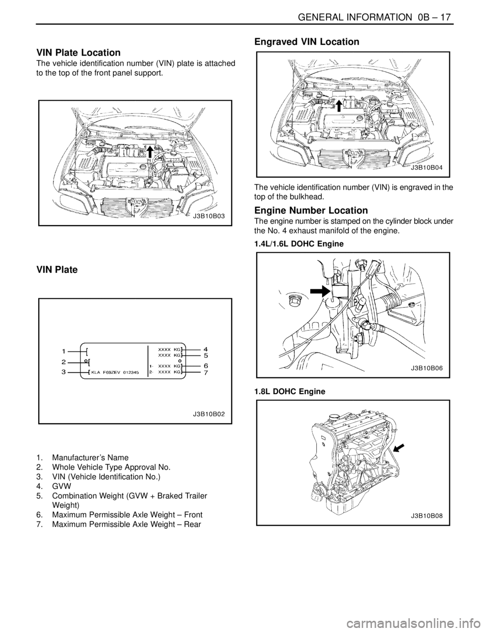
VIN Plate Location
The vehicle identification number (VIN) plate is attached
to the top of the front panel support.
VIN Plate
1. Manufacturer ’s Name
2. Whole Vehicle Type Approval No.
3. VIN (Vehicle Identification No.)
4. GVW
5. Combination Weight (GVW + Braked Trailer
Weight)
6. Maximum Permissible Axle Weight – Front
7. Maximum Permissible Axle Weight – Rear
Engraved VIN Location
The vehicle identification number (VIN) is engraved in the
top of the bulkhead.
Engine Number Location
The engine number is stamped on the cylinder block under
the No. 4 exhaust manifold of the engine.
1.4L/1.6L DOHC Engine
1.8L DOHC Engine
Page 38 of 2643

1A – 6IGENERAL ENGINE INFORMATION
DAEWOO V–121 BL4
Light Knock Hot
StepActionValue(s)YesNo
1Is there a light knock when the engine is hot?–Go to Step 2System OK
2Is detonation or spark knock evident?–Go to Step 3Go to Step 4
3Check the engine timing and the fuel quality.
Was the problem found?–Go to Step 1–
4Inspect the torque converter bolts.
Are the bolts tightened to the specified value?45 NSm
(33 lb–ft)Go to Step 5Go to Step 6
5Tighten the torque converter bolts.
Is the repair complete?–Go to Step 1–
6Inspect the manifold.
Is there an exhaust leak at the manifold?–Go to Step 7Go to Step 8
7Tighten the bolts or replace the gasket.
Is the repair complete?–Go to Step 1–
8Check the rod bearing clearance.
Is the clearance within the specified value?0.019 ~
0.070 mm
(0.0007 ~
0.0028 in.)Go to Step 9System OK
9Replace the rod bearings, as necessary.
Is the repair complete?–Go to Step 1–
Knocks During Initial Start–Up But Last Only a Few Seconds
StepActionValue(s)YesNo
1Does the engine knock during initial start–up but last
only a few seconds?–Go to Step 2System OK
2Check the engine oil.
Is the proper viscosity oil used in the crankcase?–Go to Step 4Go to Step 3
3Install oil of the proper viscosity for the expected
seasonal temperatures.
Is the repair complete?–Go to Step 1–
4Inspect the hydraulic lifters.
Is there evidence of hydraulic lifter bleed–down?–Go to Step 5Go to Step 6
5Clean, test and replace the lifters, as necessary.
Is the repair complete?*–Go to Step 1–
6Inspect the crankshaft end clearance.
Is the clearance more than specified value?0.1 mm
(0.0039 in.)Go to Step 7Go to Step 8
7Replace the crankshaft thrust bearing.
Is the repair complete?–Go to Step 1–
8Inspect the front main bearing clearance.
Is the clearance more than the specified value?0.026~0.046
mm (0.0010~
0.0018 in.)Go to Step 9System OK
9Replace the worn parts of the front main bearing.
Is the repair complete?–Go to Step 1–
* When the engine is stopped, some valves will be open. Spring pressure against the lifters will tend to bleed lifter down.
Attempts to repair this should be made only if the problem is consistent.
An engine that is only operated for short periods between start–ups may have lifter noise that lasts for a few minutes. This
is a normal condition.
Page 44 of 2643

SECTION : 1C1
1.4L/1.6L DOHC ENGINE MECHANICAL
CAUTION : Disconnect the negative battery cable before removing or installing any electrical unit or when a tool
or equipment could easily come in contact with exposed electrical terminals. Disconnecting this cable will help
prevent personal injury and damage to the vehicle. The ignition must also be in LOCK unless otherwise noted.
TABLE OF CONTENTS
SPECIFICATIONS1C1–2 . . . . . . . . . . . . . . . . . . . . . . . . .
Engine Specifications 1C1–2. . . . . . . . . . . . . . . . . . . . .
Fastener Tightening Specifcations 1C1–5. . . . . . . . . .
SPECIAL TOOLS1C1–7 . . . . . . . . . . . . . . . . . . . . . . . . . .
Special Tools Table 1C1–7. . . . . . . . . . . . . . . . . . . . . . .
COMPONENT LOCATOR1C1–9 . . . . . . . . . . . . . . . . . . .
Cylinder Head 1C1–9. . . . . . . . . . . . . . . . . . . . . . . . . . . .
Cylinder Block 1C1–10. . . . . . . . . . . . . . . . . . . . . . . . . . .
Intake & Exhaust Manifold 1C1–12. . . . . . . . . . . . . . . .
Timing Belt 1C1–13. . . . . . . . . . . . . . . . . . . . . . . . . . . . .
Engine Mounting 1C1–14. . . . . . . . . . . . . . . . . . . . . . . .
MAINTENANCE AND REPAIR1C1–15 . . . . . . . . . . . . .
ON–VEHICLE SERVICE 1C1–15. . . . . . . . . . . . . . . . . . .
Engine Cover 1C1–15. . . . . . . . . . . . . . . . . . . . . . . . . . .
Camshaft Cover 1C1–15. . . . . . . . . . . . . . . . . . . . . . . . .
Intake Manifold 1C1–16. . . . . . . . . . . . . . . . . . . . . . . . . .
Exhaust Manifold 1C1–20. . . . . . . . . . . . . . . . . . . . . . . .
Cylinder Head and Gasket 1C1–21. . . . . . . . . . . . . . . .
Camshaft 1C1–29. . . . . . . . . . . . . . . . . . . . . . . . . . . . . . .
Timing Belt Check and Adjust 1C1–30. . . . . . . . . . . . .
Timing Belt 1C1–34. . . . . . . . . . . . . . . . . . . . . . . . . . . . . Oil Pan 1C1–38. . . . . . . . . . . . . . . . . . . . . . . . . . . . . . . . .
Oil Pump 1C1–40. . . . . . . . . . . . . . . . . . . . . . . . . . . . . . .
Engine Mount 1C1–43. . . . . . . . . . . . . . . . . . . . . . . . . . .
Camshaft Gears 1C1–45. . . . . . . . . . . . . . . . . . . . . . . . .
Rear Timing Belt Cover 1C1–46. . . . . . . . . . . . . . . . . . .
Engine 1C1–48. . . . . . . . . . . . . . . . . . . . . . . . . . . . . . . . .
Pistons and Rods 1C1–53. . . . . . . . . . . . . . . . . . . . . . . .
UNIT REPAIR 1C1–58. . . . . . . . . . . . . . . . . . . . . . . . . . . .
Cylinder Head and Valve Train Components 1C1–58.
Crankshaft 1C1–65. . . . . . . . . . . . . . . . . . . . . . . . . . . . . .
Crankshaft Bearing and Connecting Rod
Beadings – Gauging Plastics 1C1–74. . . . . . . . . . . .
GENERAL DESCRIPTION AND SYSTEM
OPERATION1C1–77 . . . . . . . . . . . . . . . . . . . . . . . . . . . .
Cylinder Head and Gasket 1C1–77. . . . . . . . . . . . . . . .
Crankshaft 1C1–77. . . . . . . . . . . . . . . . . . . . . . . . . . . . . .
Timing Belt 1C1–77. . . . . . . . . . . . . . . . . . . . . . . . . . . . .
Oil Pump 1C1–77. . . . . . . . . . . . . . . . . . . . . . . . . . . . . . .
Oil Pan 1C1–77. . . . . . . . . . . . . . . . . . . . . . . . . . . . . . . . .
Exhaust Manifold 1C1–77. . . . . . . . . . . . . . . . . . . . . . . .
Intake Manifold 1C1–77. . . . . . . . . . . . . . . . . . . . . . . . . .
Camshaft 1C1–77. . . . . . . . . . . . . . . . . . . . . . . . . . . . . . .
Page 47 of 2643

1C1 – 4I1.4L/1.6L DOHC ENGINE MECHANICAL
DAEWOO V–121 BL4
ApplicationDescription (Manual and Automatic)
1.4L DOHC1.6L DOHC
Inner Rotor Side Clearance0.035~0.085 mm (0.001~0.003 in.)0.035~0.085 mm (0.001~0.003 in.)
Relief Valve Spring Free Length81 mm (3.2 in.)81 mm (3.2 in.)
Sealants and Adhesives:
Rear Main Bearing CapGE p/n RTV 159
Camshaft Carrier to Cylinder HeadHN 1581 (Loctite® 515)
Oil Pan BoltsHN 1256 (Loctite® 242)
Oil Pump BoltsHN 1256 (Loctite® 242)
Oil Pan Pickup Tube BoltsHN 1256 (Loctite® 242)
Oil Gallery PlugHN 1256 (Loctite® 242)
Coolant Jacket Caps and Plugs
(Freeze Plugs)HN 1756 (Loctite® 176)
Exhaust Manifold Studs/NutsAnti–seize Compound (HMC Spec HN1325)
Page 48 of 2643

1.4L/1.6L DOHC ENGINE MECHANICAL 1C1 – 5
DAEWOO V–121 BL4
FASTENER TIGHTENING SPECIFCATIONS
ApplicationNSmLb–FtLb–In
Air Cleaner Housing Bolts10–89
Camshaft Cap Bolts1612–
Camshaft Cover Nuts10–89
Connecting Rod Bearing Cap Bolts25
+ 30° + 15°18
+ 30° + 15°–
Coolant Temperature Sensor2015–
Crankshaft Bearing Cap Bolts50
+ 45° + 15°37
+ 45°+ 15°–
Crankshaft Cover Nuts5~8–44~71
Crankshaft Pulley Bolt95 NSm
+ 30° + 15°––
Cylinder Head Bolts (Cylinder Head Mounting Bolts)25 + 70°
+ 70° + 50°18 + 70°
+ 70° + 50°–
Direct Ignition System Coil Mounting Bolts10–89
Direct Ignition System Coil Mounting Bracket Bolts10–89
Engine Mount Attaching Bolts3022–
Engine Mount Bracket Attaching Bolts/Nuts5037–
Exhaust Camshaft Gear Bolt67.549–
Exhaust Flex Pipe–to–Catalytic Converter or Connecting Pipe
Retaining Nut3526–
Exhaust Flex Pipe–to–Exhaust Manifold Retaining Nuts3526–
Exhaust Gas Recirculation Valve Adapter Bolts2518–
Exhaust Manifold Heat Shield Bolts1511–
Exhaust Manifold Retaining Nuts2518–
Flexible Plate Bolts6044–
Flexible Plate Inspection Cover Bolts10–89
Flywheel Bolts35
+ 30° + 15°25
+ 30° + 15°–
Flywheel Inspection Cover Bolts12–106
Front Timing Belt Cover Bolts (Upper and Lower)10–89
Fuel Rail Assembly Retaining Bolts2518–
Fuel Rail Retaining Bolts2518–
Generator Upper Retaining Bolt2015–
Intake Camshaft Gear Bolt67.549–
Intake Manifold Retaining Bolts/Nuts2518–
Intake Manifold Support Bracket Lower Bolt2518–
Intake Manifold Support Bracket Upper Bolts2518–
Lower Front Timing Belt Cover Bolts10–89
Oil Pan Flange Bolts7555–
Oil Pan Retaining Bolts10–89
Oil Pan Drain Plug3526–
OIl Pressure Switch4030–
Page 55 of 2643

1C1 – 12I1.4L/1.6L DOHC ENGINE MECHANICAL
DAEWOO V–121 BL4
INTAKE & EXHAUST MANIFOLD
1. Oxygen Sensor
2. Heat Shield
3. Exhaust Manifold
4. Exhaust Manifold Gasket
5. Intake Manifold
6. Main Throttle Idle Actuator (MTIA) Gasket
7. MTIA
8. Clamp9. Intake Air Tube
10. Breethe Hose
11. Aircleaner Assembly
12. Aircleaner Upper Hosing
13. Aircleaner Eliment
14. Aircleaner Lower Housing
15. Resoinator
16. Air Intet Hose
Page 59 of 2643
1C1 – 16I1.4L/1.6L DOHC ENGINE MECHANICAL
DAEWOO V–121 BL4
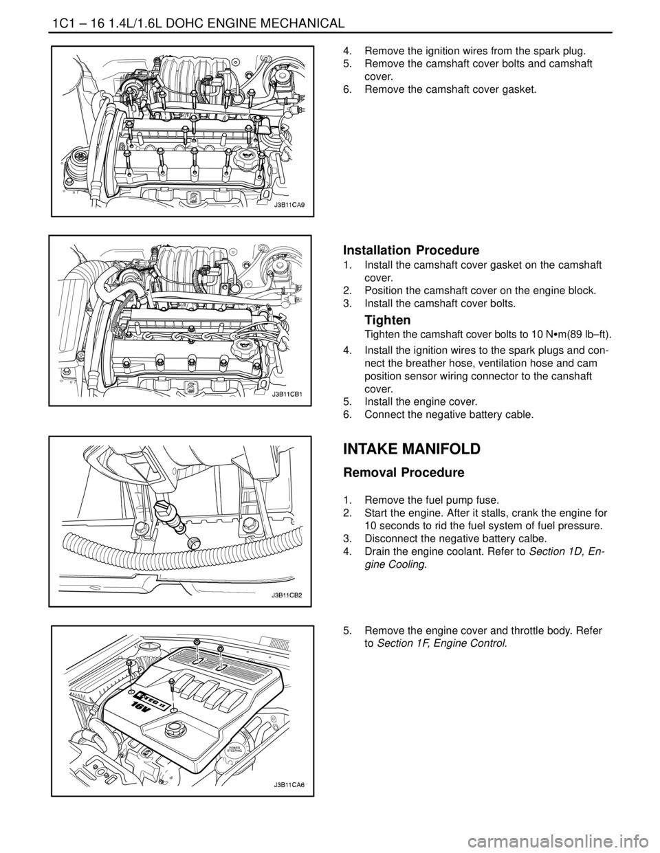
4. Remove the ignition wires from the spark plug.
5. Remove the camshaft cover bolts and camshaft
cover.
6. Remove the camshaft cover gasket.
Installation Procedure
1. Install the camshaft cover gasket on the camshaft
cover.
2. Position the camshaft cover on the engine block.
3. Install the camshaft cover bolts.
Tighten
Tighten the camshaft cover bolts to 10 NSm(89 lb–ft).
4. Install the ignition wires to the spark plugs and con-
nect the breather hose, ventilation hose and cam
position sensor wiring connector to the canshaft
cover.
5. Install the engine cover.
6. Connect the negative battery cable.
INTAKE MANIFOLD
Removal Procedure
1. Remove the fuel pump fuse.
2. Start the engine. After it stalls, crank the engine for
10 seconds to rid the fuel system of fuel pressure.
3. Disconnect the negative battery calbe.
4. Drain the engine coolant. Refer to Section 1D, En-
gine Cooling.
5. Remove the engine cover and throttle body. Refer
to Section 1F, Engine Control.
Page 60 of 2643
1.4L/1.6L DOHC ENGINE MECHANICAL 1C1 – 17
DAEWOO V–121 BL4
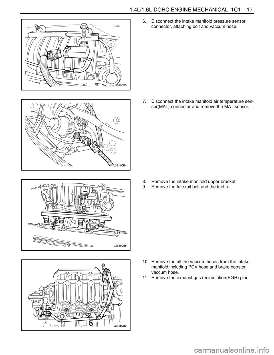
6. Disconnect the intake manifold pressure sensor
connector, attaching bolt and vaccum hose.
7. Disconnect the intake manifold air temperature sen-
sor(MAT) connector and remove the MAT sensor.
8. Remove the intake manifold upper bracket.
9. Remove the fule rail bolt and the fuel rail.
10. Remove the all the vaccum hoses from the intake
manifold including PCV hose and brake booster
vaccum hose.
11. Remove the exhaust gas recirculation(EGR) pipe.
Page 61 of 2643
1C1 – 18I1.4L/1.6L DOHC ENGINE MECHANICAL
DAEWOO V–121 BL4
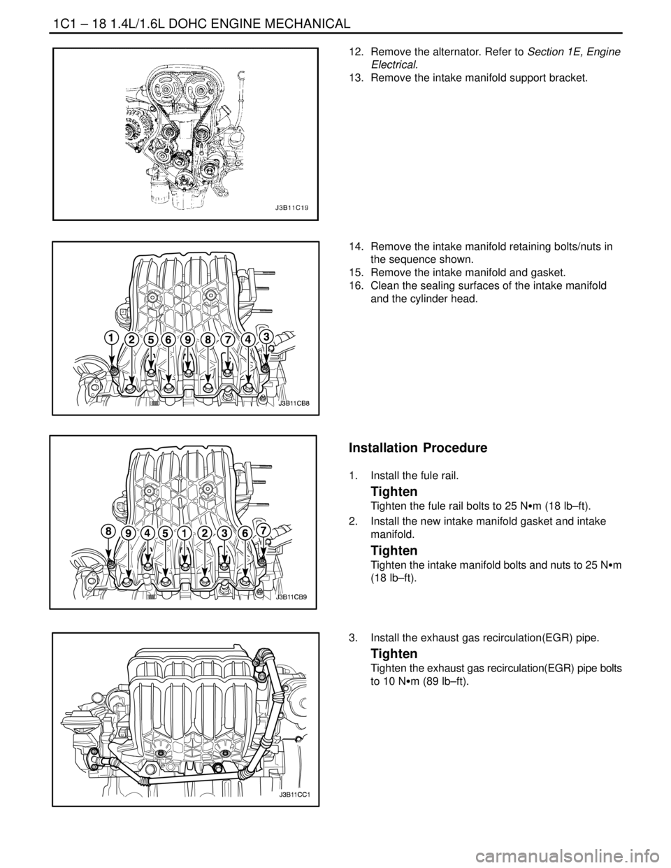
12. Remove the alternator. Refer to Section 1E, Engine
Electrical.
13. Remove the intake manifold support bracket.
14. Remove the intake manifold retaining bolts/nuts in
the sequence shown.
15. Remove the intake manifold and gasket.
16. Clean the sealing surfaces of the intake manifold
and the cylinder head.
Installation Procedure
1. Install the fule rail.
Tighten
Tighten the fule rail bolts to 25 NSm (18 lb–ft).
2. Install the new intake manifold gasket and intake
manifold.
Tighten
Tighten the intake manifold bolts and nuts to 25 NSm
(18 lb–ft).
3. Install the exhaust gas recirculation(EGR) pipe.
Tighten
Tighten the exhaust gas recirculation(EGR) pipe bolts
to 10 NSm (89 lb–ft).
Page 62 of 2643
1.4L/1.6L DOHC ENGINE MECHANICAL 1C1 – 19
DAEWOO V–121 BL4
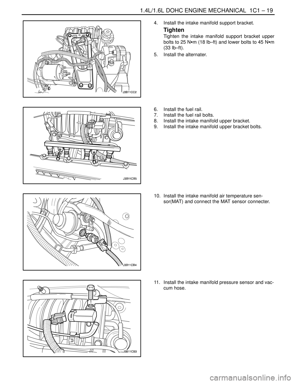
4. Install the intake manifold support bracket.
Tighten
Tighten the intake manifold support bracket upper
bolts to 25 NSm (18 lb–ft) and lower bolts to 45 NSm
(33 lb–ft).
5. Install the alternater.
6. Install the fuel rail.
7. Install the fuel rail bolts.
8. Install the intake manifold upper bracket.
9. Install the intake manifold upper bracket bolts.
10. Install the intake manifold air temperature sen-
sor(MAT) and connect the MAT sensor connecter.
11. Install the intake manifold pressure sensor and vac-
cum hose.