fill cap DAEWOO NUBIRA 2004 Service Repair Manual
[x] Cancel search | Manufacturer: DAEWOO, Model Year: 2004, Model line: NUBIRA, Model: DAEWOO NUBIRA 2004Pages: 2643, PDF Size: 80.54 MB
Page 16 of 2643
GENERAL INFORMATION 0B – 9
DAEWOO V–121 BL4
MAINTENANCE AND REPAIR
MAINTENANCE AND LUBRICATION
NORMAL VEHICLE USE
The maintenance instructions contained in the mainte-
nance schedule are based on the assumption that the ve-
hicle will be used for the following reasons:
S To carry passengers and cargo within the limitation
indicated on the tire placard located on the edge of
the driver’s door.
S To be driven on reasonable road surfaces and with-
in legal operating limits.
EXPLANATION OF SCHEDULED
MAINTENANCE SERVICES
The services listed in the maintenance schedule are fur-
ther explained below. When the following maintenance
services are performed, make sure all the parts are re-
placed and all the necessary repairs are done before driv-
ing the vehicle. Always use the proper fluid and lubricants.
Drive Belt Inspection
When a separate belt drives the power steering pump, the
air conditioning compressor and the generator, inspect it
for cracks, fraying, wear and proper tension. Adjust or re-
place the belt as needed.
Engine Oil and Oil Filter Change
API Classifications of Engine Oil
The International Lubricant Standardization and Approval
Committee (ILSAC) and American Petroleum Institute
classifies engine oils according to their performance quali-
ty. Always use oil rated API–SL (ILSAC GF–III) or better.
Engine Oil Viscosity
Engine oil viscosity (thickness) has an effect on fuel econ-
omy and cold weather operation. Lower viscosity engine
oils can provide better fuel economy and cold weather per-
formance; however, higher temperature weather condi-
tions require higher viscosity engine oils for satisfactory lu-
brication. Using oils of any viscosity other than those
viscosities recommended could result in engine damage.
Cooling System Service
Drain, flush and refill the system with new coolant. Refer
to ”Recommended Fluids And Lubricants” in this section.
Fuel Micro–Filter Replacement
Replace the engine fuel filter every 45,000 km (27,000
miles).
Air Cleaner Element Replacement
Replace the air cleaner element every 45,000 km (27,000
miles).Replace the air cleaner more often under dusty conditions.
Throttle Body Mounting Bolt Torque
Check the torque of the mounting bolts.
Tighten the throttle body mounting bolts to 15 NSm (11 lb–
ft) if necessary.
Spark Plug Replacement
Replace spark plugs with the same type.
Spark Plug Wire Replacement
Clean wires and inspect them for burns, cracks or other
damage. Check the wire boot fit at the DIS module and at
the spark plugs. Replace the wires as needed.
Brake System Service
Check the disc brake pads and the drum brake linings ev-
ery 15,000 km (9,000 miles) or 12 months. Check the pad
and the lining thickness carefully. If the pads or the linings
are not expected to last to the next scheduledmaintenance
service, replace the pads or the linings. Check the breath-
er hole in the brake fluid reservoir cap to be sure it is free
from dirt and the passage is open.
Transaxle Service
The manual transaxle fluid does not require changing. For
automatic transaxles, refer to ”Scheduled Maintenance
Charts” in this section.
Tire and Wheel Inspection and Rotation
Check the tires for abnormal wear or damage. To equalize
wear and obtain maximum tire life, rotate the tires. If irreg-
ular or premature wear exists, check the wheel alignment
and check for damaged wheels. While the tires and
wheels are removed, inspect the brakes. Refer to ”Each
Time The Oil Is Changed” in this section.
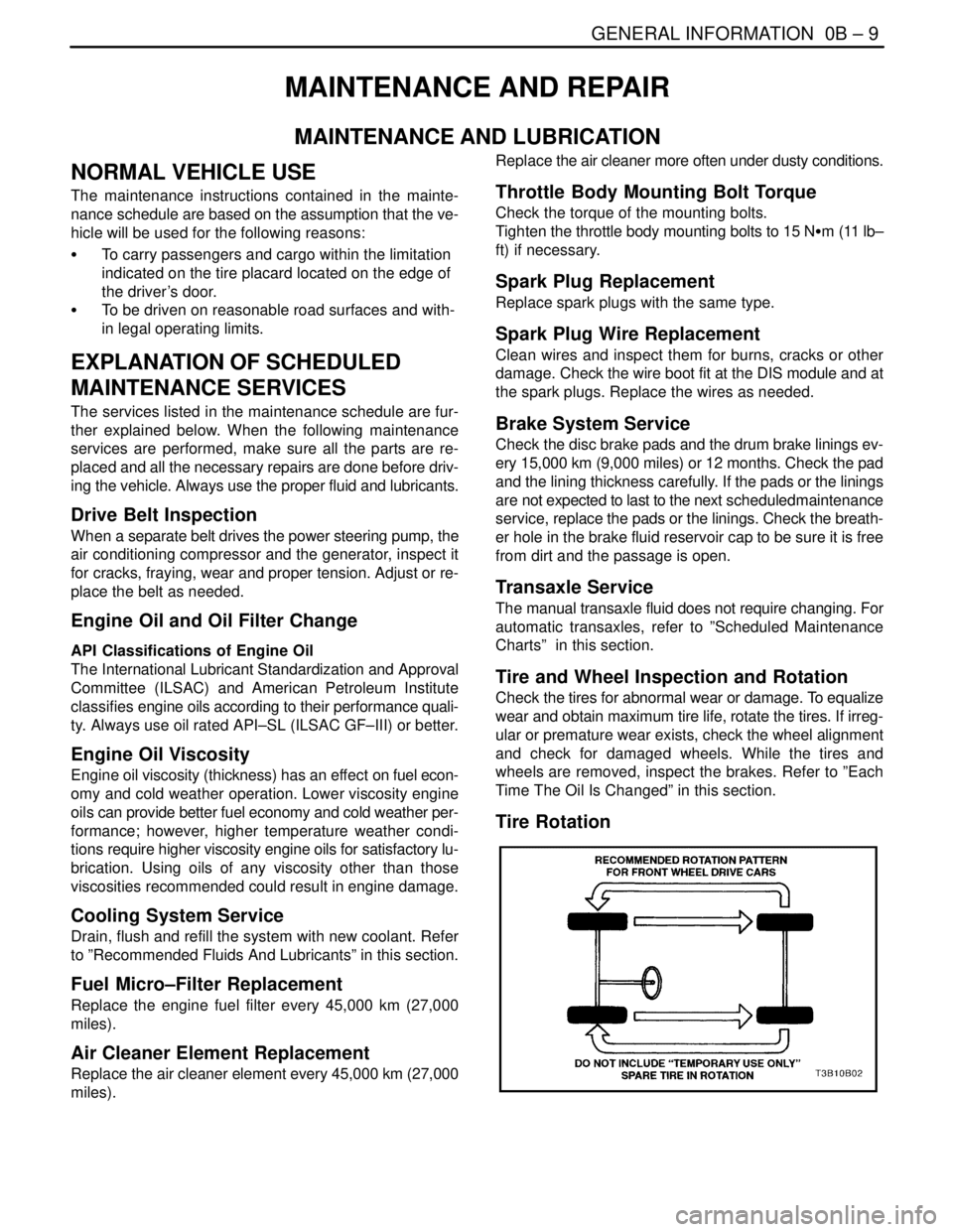
Tire Rotation
Page 21 of 2643

0B – 14IGENERAL INFORMATION
DAEWOO V–121 BL4
Engine Cooling System
Inspect the coolant and freeze protection fluid. If the fluid
is dirty or rusty, drain, flush and refill the engine cooling
system with new coolant. Keep the coolant at the proper
mixture in order to ensure proper freeze protection, corro-sion protection and engine operating temperature. Inspect
the hoses. Replace the cracked, swollen, or deteriorated
hoses. Tighten the clamps. Clean the outside of the radia-
tor and the air conditioning condenser. Wash the filler cap
and the neck. Pressure test the cooling system and the
cap in order to help ensure proper operation.
RECOMMENDED FLUIDS AND LUBRICANTS
UsageCapacityFluid/Lubricant
Engine Oil3.75L (4.0 qt) : 1.4L DOHC
3.75L (4.0 qt) : 1.6L DOHC
4.0L (4.2 qt) : 1.8L DOHCAPI SL (ILSAC GF–III) grade or better
SAE 5W–30, SAE10W–30, SAE15W–40
(Cold area : SAE5W–30
Hot area : SAE 15W–40)
Engine Coolant7.0L (7.49 qt) : 1.4L DOHC
7.2L (7.6 qt) : 1.6L DOHC
7.4L (7.8 qt) : 1.8L DOHCMixture of water and good quality ethylene gly-
col base antifreeze (year–round coolant)
Brake Fluid and Clutch Fluid0.5L (0.5 qt)DOT–3 or DOT–4
Power Steering System1.1L (1.2 qt)DEXRON®–III or DEXRON®–IID
Automatic Transaxle5.77 ± 0.2L (6.1 ± 0.2 qts) :
1.6L DOHC (AISIN 81–40LE)ESSO JWS 3309 or ISU DEXRON III
6.9 ± 0.2L (7.3 ± 0.2 qts) :
1.8L DOHC (ZF 4HP16)ESSO LT 71141 or TOTAL ATF H50235
Manual Transaxle1.8L (2.0 qt)Manual Transaxle Fluid
SAE80W (Cold Area : SAE 75W)
Manual Transaxle Shift LinkageAs requiredMultipurpose type grease meeting require-
ments NLGI No. 1 or 2
Key Lock CylindersAs requiredSilicone lubricant
Automatic Transaxle Shift Link-
ageAs requiredEngine oil
Clutch Linkage Pivot PointsAs requiredEngine oil
Floor Shift Linkage PointsAs requiredEngine oil
Hood Latch Assembly
a. Pivots and Spring Anchor
b. Release PawlAs requireda. Engine oil
b. Multipurpose type grease meeting require-
ments NLGI No. 1 or 2
Hood and door hinges
Fuel door hinge
Rear compartment lid hingesAs requiredEngine oil
WeatherstripsAs requiredSilicone grease
Page 52 of 2643
1.4L/1.6L DOHC ENGINE MECHANICAL 1C1 – 9
DAEWOO V–121 BL4
COMPONENT LOCATOR
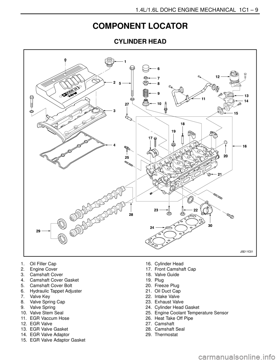
CYLINDER HEAD
1. Oil Filler Cap
2. Engine Cover
3. Camshaft Cover
4. Camshaft Cover Gasket
5. Camshaft Cover Bolt
6. Hydraulic Tappet Adjuster
7. Valve Key
8. Valve Spring Cap
9. Valve Spring
10. Valve Stem Seal
11. EGR Vaccum Hose
12. EGR Valve
13. EGR Valve Gasket
14. EGR Valve Adaptor
15. EGR Valve Adaptor Gasket16. Cylinder Head
17. Front Camshaft Cap
18. Valve Guide
19. Plug
20. Freeze Plug
21. Oil Duct Cap
22. Intake Valve
23. Exhaust Valve
24. Cylinder Head Gasket
25. Engine Coolant Temperature Sensor
26. Heat Take Off Pipe
27. Camshaft
28. Camshaft Seal
29. Thermostat
Page 70 of 2643
1.4L/1.6L DOHC ENGINE MECHANICAL 1C1 – 27
DAEWOO V–121 BL4
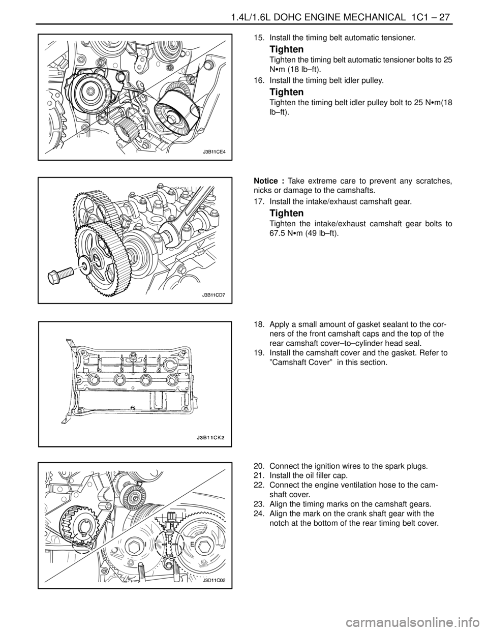
15. Install the timing belt automatic tensioner.
Tighten
Tighten the timing belt automatic tensioner bolts to 25
NSm (18 lb–ft).
16. Install the timing belt idler pulley.
Tighten
Tighten the timing belt idler pulley bolt to 25 NSm(18
lb–ft).
Notice : Take extreme care to prevent any scratches,
nicks or damage to the camshafts.
17. Install the intake/exhaust camshaft gear.
Tighten
Tighten the intake/exhaust camshaft gear bolts to
67.5 NSm (49 lb–ft).
18. Apply a small amount of gasket sealant to the cor-
ners of the front camshaft caps and the top of the
rear camshaft cover–to–cylinder head seal.
19. Install the camshaft cover and the gasket. Refer to
”Camshaft Cover” in this section.
20. Connect the ignition wires to the spark plugs.
21. Install the oil filler cap.
22. Connect the engine ventilation hose to the cam-
shaft cover.
23. Align the timing marks on the camshaft gears.
24. Align the mark on the crank shaft gear with the
notch at the bottom of the rear timing belt cover.
Page 72 of 2643
1.4L/1.6L DOHC ENGINE MECHANICAL 1C1 – 29
DAEWOO V–121 BL4
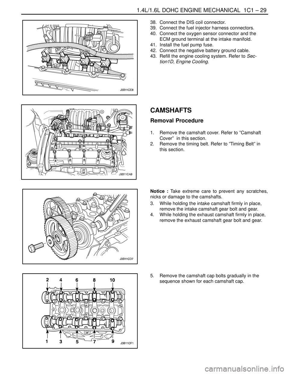
38. Connect the DIS coil connector.
39. Connect the fuel injector harness connectors.
40. Connect the oxygen sensor connector and the
ECM ground terminal at the intake manifold.
41. Install the fuel pump fuse.
42. Connect the negative battery ground cable.
43. Refill the engine cooling system. Refer to Sec-
tion1D, Engine Cooling.
CAMSHAFTS
Removal Procedure
1. Remove the camshaft cover. Refer to ”Camshaft
Cover” in this section.
2. Remove the timing belt. Refer to ”Timing Belt” in
this section.
Notice : Take extreme care to prevent any scratches,
nicks or damage to the camshafts.
3. While holding the intake camshaft firmly in place,
remove the intake camshaft gear bolt and gear.
4. While holding the exhaust camshaft firmly in place,
remove the exhaust camshaft gear bolt and gear.
5. Remove the camshaft cap bolts gradually in the
sequence shown for each camshaft cap.
Page 96 of 2643
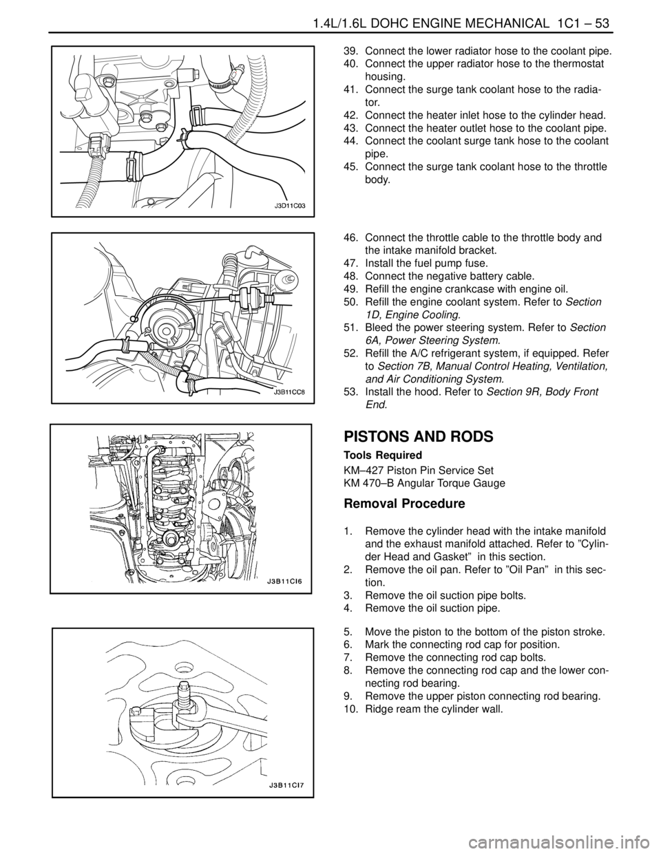
1.4L/1.6L DOHC ENGINE MECHANICAL 1C1 – 53
DAEWOO V–121 BL4
39. Connect the lower radiator hose to the coolant pipe.
40. Connect the upper radiator hose to the thermostat
housing.
41. Connect the surge tank coolant hose to the radia-
tor.
42. Connect the heater inlet hose to the cylinder head.
43. Connect the heater outlet hose to the coolant pipe.
44. Connect the coolant surge tank hose to the coolant
pipe.
45. Connect the surge tank coolant hose to the throttle
body.
46. Connect the throttle cable to the throttle body and
the intake manifold bracket.
47. Install the fuel pump fuse.
48. Connect the negative battery cable.
49. Refill the engine crankcase with engine oil.
50. Refill the engine coolant system. Refer to Section
1D, Engine Cooling.
51. Bleed the power steering system. Refer to Section
6A, Power Steering System.
52. Refill the A/C refrigerant system, if equipped. Refer
to Section 7B, Manual Control Heating, Ventilation,
and Air Conditioning System.
53. Install the hood. Refer to Section 9R, Body Front
End.
PISTONS AND RODS
Tools Required
KM–427 Piston Pin Service Set
KM 470–B Angular Torque Gauge
Removal Procedure
1. Remove the cylinder head with the intake manifold
and the exhaust manifold attached. Refer to ”Cylin-
der Head and Gasket” in this section.
2. Remove the oil pan. Refer to ”Oil Pan” in this sec-
tion.
3. Remove the oil suction pipe bolts.
4. Remove the oil suction pipe.
5. Move the piston to the bottom of the piston stroke.
6. Mark the connecting rod cap for position.
7. Remove the connecting rod cap bolts.
8. Remove the connecting rod cap and the lower con-
necting rod bearing.
9. Remove the upper piston connecting rod bearing.
10. Ridge ream the cylinder wall.
Page 110 of 2643
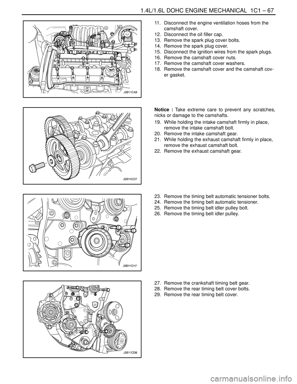
1.4L/1.6L DOHC ENGINE MECHANICAL 1C1 – 67
DAEWOO V–121 BL4
11. Disconnect the engine ventilation hoses from the
camshaft cover.
12. Disconnect the oil filler cap.
13. Remove the spark plug cover bolts.
14. Remove the spark plug cover.
15. Disconnect the ignition wires from the spark plugs.
16. Remove the camshaft cover nuts.
17. Remove the camshaft cover washers.
18. Remove the camshaft cover and the camshaft cov-
er gasket.
Notice : Take extreme care to prevent any scratches,
nicks or damage to the camshafts.
19. While holding the intake camshaft firmly in place,
remove the intake camshaft bolt.
20. Remove the intake camshaft gear.
21. While holding the exhaust camshaft firmly in place,
remove the exhaust camshaft bolt.
22. Remove the exhaust camshaft gear.
23. Remove the timing belt automatic tensioner bolts.
24. Remove the timing belt automatic tensioner.
25. Remove the timing belt idler pulley bolt.
26. Remove the timing belt idler pulley.
27. Remove the crankshaft timing belt gear.
28. Remove the rear timing belt cover bolts.
29. Remove the rear timing belt cover.
Page 116 of 2643
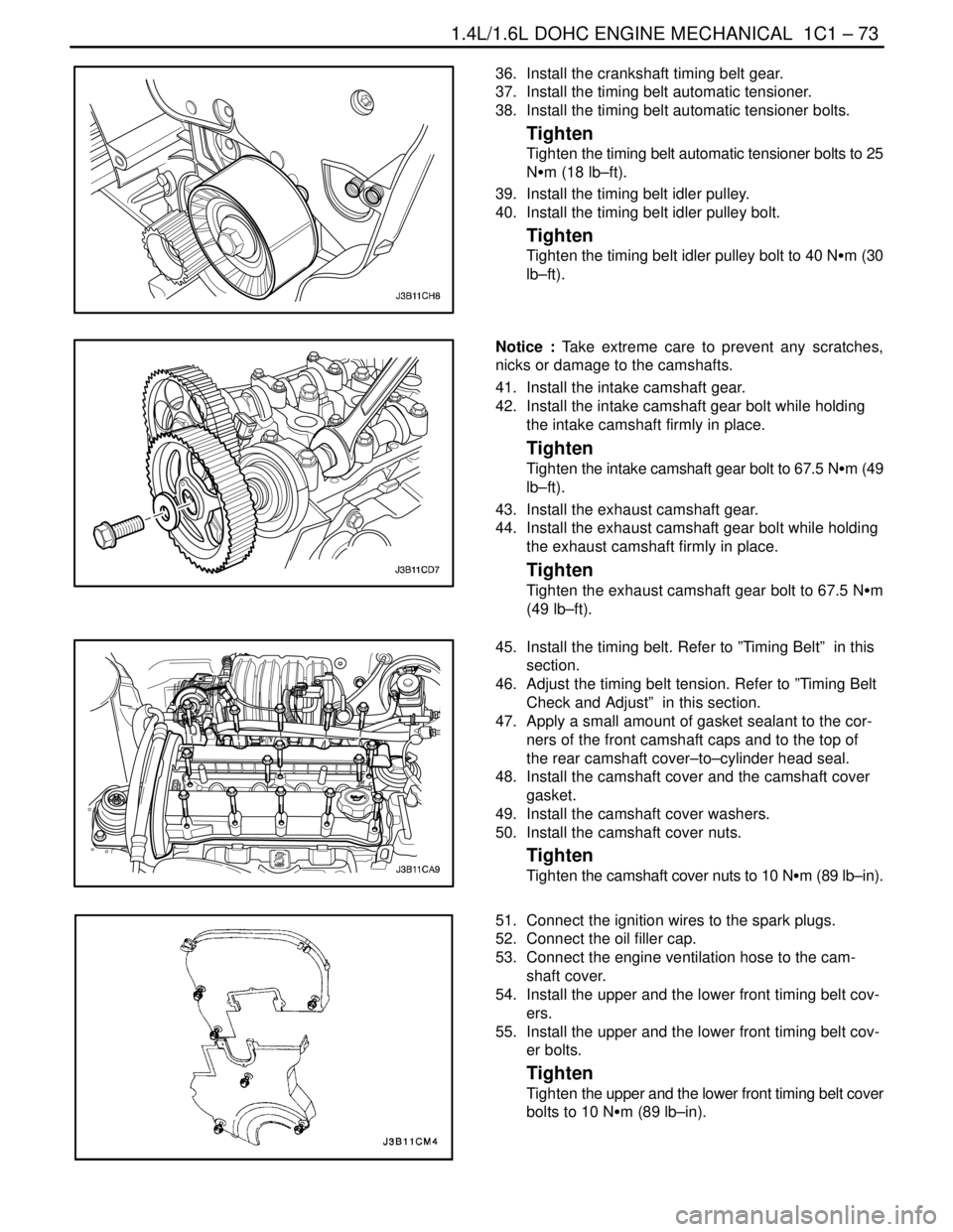
1.4L/1.6L DOHC ENGINE MECHANICAL 1C1 – 73
DAEWOO V–121 BL4
36. Install the crankshaft timing belt gear.
37. Install the timing belt automatic tensioner.
38. Install the timing belt automatic tensioner bolts.
Tighten
Tighten the timing belt automatic tensioner bolts to 25
NSm (18 lb–ft).
39. Install the timing belt idler pulley.
40. Install the timing belt idler pulley bolt.
Tighten
Tighten the timing belt idler pulley bolt to 40 NSm (30
lb–ft).
Notice : Take extreme care to prevent any scratches,
nicks or damage to the camshafts.
41. Install the intake camshaft gear.
42. Install the intake camshaft gear bolt while holding
the intake camshaft firmly in place.
Tighten
Tighten the intake camshaft gear bolt to 67.5 NSm (49
lb–ft).
43. Install the exhaust camshaft gear.
44. Install the exhaust camshaft gear bolt while holding
the exhaust camshaft firmly in place.
Tighten
Tighten the exhaust camshaft gear bolt to 67.5 NSm
(49 lb–ft).
45. Install the timing belt. Refer to ”Timing Belt” in this
section.
46. Adjust the timing belt tension. Refer to ”Timing Belt
Check and Adjust” in this section.
47. Apply a small amount of gasket sealant to the cor-
ners of the front camshaft caps and to the top of
the rear camshaft cover–to–cylinder head seal.
48. Install the camshaft cover and the camshaft cover
gasket.
49. Install the camshaft cover washers.
50. Install the camshaft cover nuts.
Tighten
Tighten the camshaft cover nuts to 10 NSm (89 lb–in).
51. Connect the ignition wires to the spark plugs.
52. Connect the oil filler cap.
53. Connect the engine ventilation hose to the cam-
shaft cover.
54. Install the upper and the lower front timing belt cov-
ers.
55. Install the upper and the lower front timing belt cov-
er bolts.
Tighten
Tighten the upper and the lower front timing belt cover
bolts to 10 NSm (89 lb–in).
Page 129 of 2643

1.8L DOHC ENGINE MECHANICAL 1C2 – 9
DAEWOO V–121 BL4
1. Bolt
2. Spark Plug Cover
3. Oil Filler Cap
4. Oil Filler Cap Seal
5. Bolt
6. Camshaft Cover
7. Camshaft Cover Gasket
8. Tappet Adjuster
9. Valve Key
10. Valve Spring Cap
11. Valve Spring
12. Valve Stem Seal
13. Valve Spring Seat
14. Valve Guide
15. Intake Valve Seat Ring
16. Exhaust Valve Seat Ring
17. Intake Valve
18. Exhaust Valve
19. Bolt
20. Front Camshaft Cap
21. Head Bolt
22. Bolt
23. Intermediate Camshaft Cap
24. Exhaust Gas Recirculation Adapter
25. Exhaust Gas Recirculation Adapter Gasket
26. Cylinder Head
27. Exhaust Manifold Gasket28. Exhaust Manifold
29. Nut
30. Exhaust Manifold Heat Shield
31. Cylinder Head Gasket
32. Bolt
33. Thermostat Housing
34. Thermostat Housing Gasket
35. Stud
36. Sleeve
37. Plug
38. Bolt
39. Camshaft Position Sensor
40. Oil Gallery Plug
41. Exhaust Camshaft
42. Seal Ring
43. Camshaft Gear
44. Washer
45. Camshaft Gear Bolt
46. Intake Camshaft
47. Intake Manifold Gasket
48. Intake Manifold
49. Throttle Body Gasket
50. Throttle Body
51. Nut
52. Charcoal Canister Purge Solenoid
53. Exhaust Gas Recirculation Solenoid
Page 196 of 2643

SECTION : 1D
ENGINE COOLING
CAUTION : Disconnect the negative battery cable before removing or installing any electrical unit or when a tool
or equipment could easily come in contact with exposed electrical terminals. Disconnecting this cable will help
prevent personal injury and damage to the vehicle. The ignition must also be in LOCK unless otherwise noted.
TABLE OF CONTENTS
SPECIFICATIONS1D–2 . . . . . . . . . . . . . . . . . . . . . . . . . .
Capacity 1D–2. . . . . . . . . . . . . . . . . . . . . . . . . . . . . . . . . .
Fastener Tightening Specifications 1D–2. . . . . . . . . . .
SPECIAL TOOLS1D–2 . . . . . . . . . . . . . . . . . . . . . . . . . . .
Special Tools Table 1D–2. . . . . . . . . . . . . . . . . . . . . . . .
DIAGNOSIS1D–3 . . . . . . . . . . . . . . . . . . . . . . . . . . . . . . . .
Thermostat Test 1D–3. . . . . . . . . . . . . . . . . . . . . . . . . . .
Surge Tank Cap Test 1D–3. . . . . . . . . . . . . . . . . . . . . . .
Cooling System Diagnosis 1D–4. . . . . . . . . . . . . . . . . .
COMPONENT LOCATOR1D–5 . . . . . . . . . . . . . . . . . . . .
Radiator/Fan 1D–5. . . . . . . . . . . . . . . . . . . . . . . . . . . . . .
Water Pump/Thermostat (1.4L/1.6L DOHC) 1D–6. . .
Water Pump/Thermostat (1.8L DOHC) 1D–7. . . . . . .
MAINTENANCE AND REPAIR1D–8 . . . . . . . . . . . . . . .
ON–VEHICLE SERVICE 1D–8. . . . . . . . . . . . . . . . . . . . . Draining and Refilling the Cooling System 1D–8. . . . .
Thermostat (1.4L/1.6L DOHC) 1D–9. . . . . . . . . . . . . . .
Thermostat (1.8L DOHC) 1D–10. . . . . . . . . . . . . . . . . .
Water Pump 1D–11. . . . . . . . . . . . . . . . . . . . . . . . . . . . .
Electric Cooling Fan – Main or Auxiliary 1D–13. . . . . .
Surge Tank 1D–14. . . . . . . . . . . . . . . . . . . . . . . . . . . . . .
Radiator 1D–16. . . . . . . . . . . . . . . . . . . . . . . . . . . . . . . . .
GENERAL DESCRIPTION AND SYSTEM
OPERATION1D–18 . . . . . . . . . . . . . . . . . . . . . . . . . . . . .
General Description 1D–18. . . . . . . . . . . . . . . . . . . . . . .
Radiator 1D–18. . . . . . . . . . . . . . . . . . . . . . . . . . . . . . . . .
Surge Tank 1D–18. . . . . . . . . . . . . . . . . . . . . . . . . . . . . .
Water Pump 1D–18. . . . . . . . . . . . . . . . . . . . . . . . . . . . .
Thermostat 1D–18. . . . . . . . . . . . . . . . . . . . . . . . . . . . . .
Electric Cooling Fan 1D–19. . . . . . . . . . . . . . . . . . . . . . .
Engine Block Heater 1D–19. . . . . . . . . . . . . . . . . . . . . .