tow DATSUN 510 1968 Service Repair Manual
[x] Cancel search | Manufacturer: DATSUN, Model Year: 1968, Model line: 510, Model: DATSUN 510 1968Pages: 252, PDF Size: 12.2 MB
Page 28 of 252
ENGINE
AND
IGNITION
TUNE
UP
23
CD
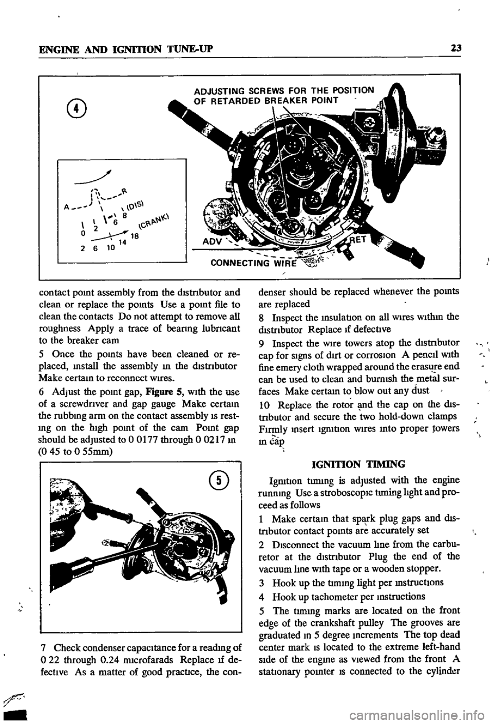
ADJUSTING
SCREWS
FOR
THE
POSITION
OF
RETARDED
BREAKER
POINT
r
A
O
S
8
6
C
0
18
2
6
10
14
contact
pomt
assembly
from
the
dIStnbutor
and
clean
or
replace
the
pomts
Use
a
pomt
file
to
clean
the
contacts
Do
not
attempt
to
remove
all
roughness
Apply
a
trace
of
beanng
lubncant
to
the
breaker
cam
5
Once
the
pomts
have
been
cleaned
or
re
placed
mstall
the
assembly
m
the
dlstnbutor
Make
certam
to
reconnect
wires
6
Adjust
the
pomt
gap
Figure
S
With
the
use
of
a
screwdnver
and
gap
gauge
Make
certaIn
the
rubbmg
arm
on
the
contact
assembly
IS
rest
mg
on
the
hIgh
pomt
of
the
carn
Pomt
gap
should
be
adjusted
to
0
0177
through
00217
m
0
45
to
0
55mm
CD
7
Check
condenser
capacItance
for
a
readmg
of
o
22
through
0
24
mIcrofarads
Replace
If
de
fectIve
As
a
matter
of
good
practIce
the
con
r
denser
should
be
replaced
whenever
the
pomts
are
replaced
8
Inspect
the
InSulatIon
on
all
WIres
WIthIn
the
dIStributor
Replace
If
defectIve
9
Inspect
the
WIre
towers
atop
the
dIStnbutor
cap
for
SignS
of
dIrt
or
corrosIOn
A
pencIl
wIth
fine
emery
cloth
wrapped
around
the
erasl
e
end
can
be
used
to
clean
and
burnISh
the
metal
sur
faces
Make
certam
to
blowout
any
dust
10
Replace
the
rotor
md
the
cap
on
the
dIs
tnbutor
and
secure
the
two
hold
down
clamps
FI
ly
msert
IgrntIon
WIres
mto
proper
towers
ill
cap
IGNITION
TIMING
IgmtIon
tIDlIDg
is
adjusted
with
the
engine
runnmg
Use
a
strobOSCOpIC
timing
hght
and
pro
ceed
as
follows
1
Make
certam
that
spl
l
k
plug
gaps
and
dIs
tnbutor
contact
pomts
are
accurately
set
2
DISconnect
the
vacuum
hne
from
the
carbu
retor
at
the
dIstrIbutor
Plug
the
end
of
the
vacuum
hne
wIth
tape
or
a
wooden
stopper
3
Hook
up
the
trmmg
light
per
mstructIons
4
Hook
up
tachometer
per
mstructions
5
The
tImmg
marles
are
located
on
the
front
edge
of
the
crankshaft
pulley
The
grooves
are
graduated
m
5
degree
mcrements
The
top
dead
center
mark
S
located
to
the
extreme
left
hand
sIde
of
the
engme
as
vIewed
from
the
front
A
statIOnary
pomter
S
connected
to
the
cylinder
Page 35 of 252
30
CHAPTER
FIVE
should
be
1
54
m
39mm
If
the
spnng
tension
is
accurate
the
rehef
valve
should
open
at
54
0
to
59
7
lb
1m
3
8
to
4
2
kg
cm
6
Reassemble
the
oil
pump
Make
certain
all
gaskets
are
mounted
flat
to
avoid
leaks
7
Install
the
dnve
spindle
and
the
oil
pump
to
the
front
cover
8
Install
the
distnbutor
in
the
same
relative
locallon
from
which
it
was
removed
If
the
num
ber
1
cyhnder
was
at
top
dead
center
on
the
compression
stroke
the
punch
mark
on
the
dnve
spindle
should
face
toward
the
front
of
the
engine
9
Install
the
front
splash
shield
and
the
front
stablhzer
10
Insert
the
drain
plug
in
the
pan
and
refill
the
engme
11
Oil
pressure
at
idle
should
be
142
to
17
1
lb
lin
1
0
to
1
2
kg
cm
12
Tlghtenmg
torque
values
for
the
oil
pump
mounting
bolts
is
10
8
to
152ft
lb
1
5
to
2
1
kg
m
and
21
69
to
25
31
ft
lb
3
0
to
25
kg
m
for
the
release
valve
cap
nut
Oil
Filter
The
oil
filter
is
mounted
on
the
nght
hand
side
of
the
cyhnder
block
It
IS
a
cartndge
type
with
built
m
gasket
and
threads
onto
the
mounting
spindle
The
filter
should
be
replaced
every
6
000
miles
as
follows
1
Dram
the
engme
oil
Walt
10
15
minutes
before
removmg
oil
filter
to
allow
It
to
dram
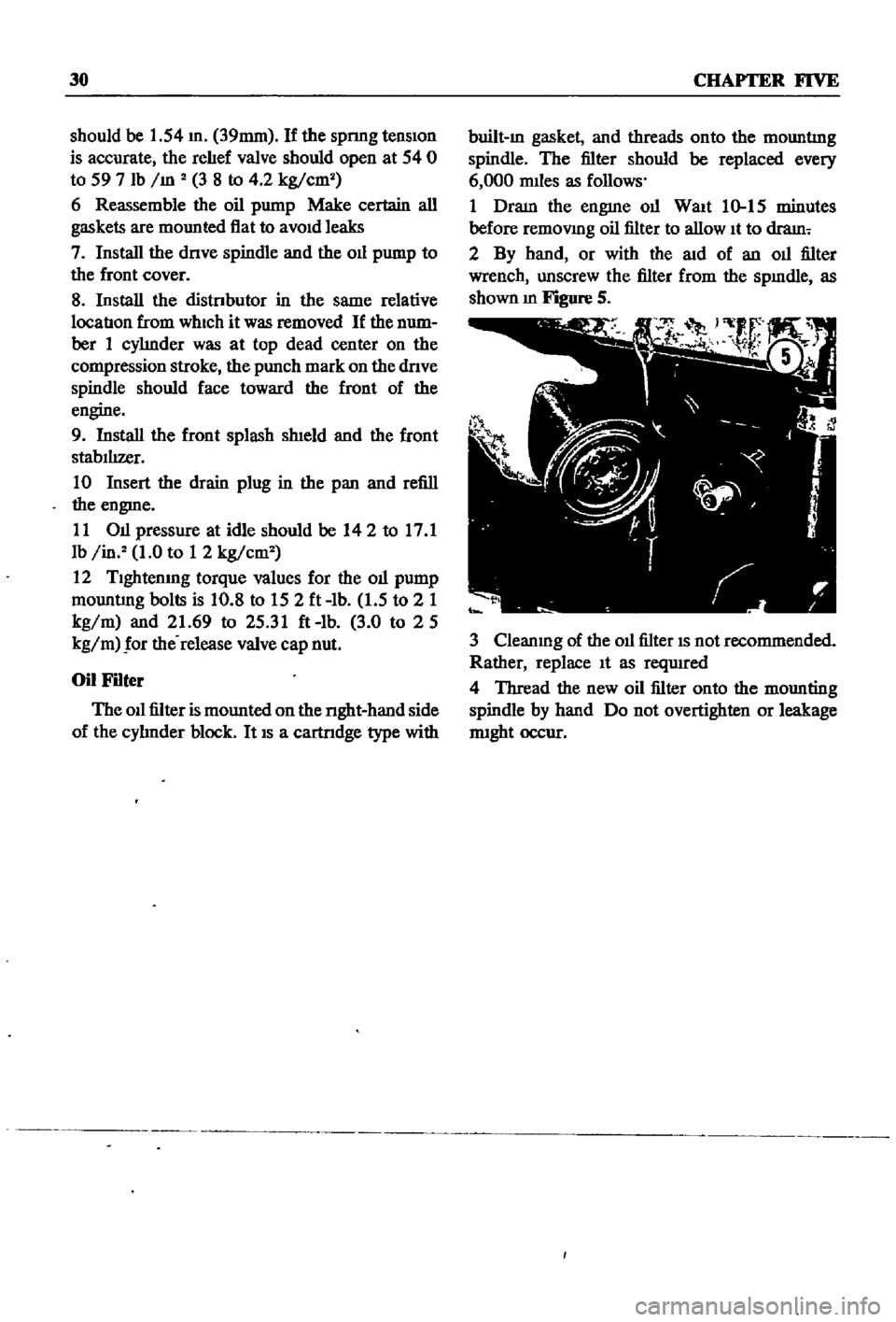
2
By
hand
or
with
the
aid
of
an
oil
filter
wrench
unscrew
the
filter
from
the
spmdle
as
shown
m
Figure
S
3
Cleanmg
of
the
oil
filter
IS
not
recommended
Rather
replace
It
as
reqUIred
4
Thread
the
new
oil
filter
onto
the
mounting
spindle
by
hand
Do
not
overtighten
or
leakage
nught
occur
Page 45 of 252
40
CHAPTER
SIX
be
removed
Hoist
the
engme
off
Its
mounts
and
adjust
the
cham
or
cable
to
tIlt
the
engme
as
shown
in
the
illustration
ContInue
to
raIse
gradually
31
Once
the
engine
and
transmission
are
clear
of
the
vehIcle
lower
them
to
a
swtable
support
or
stand
and
dIsconnect
the
hOISt
32
The
transmISSIon
can
now
be
freed
by
re
movmg
the
bolts
holdIng
the
clutch
assembly
to
the
flywheel
housing
and
movmg
the
clutch
assembly
back
to
dIsengage
the
dnve
shaft
splmes
33
Witlltlie
engIne
removed
carefiillyinspect
the
mountIng
Insulators
for
SIgnS
of
damage
or
detenoratIon
Replace
them
1f
necessary
ENGINE
DISASSEMBLY
ThIS
sectIon
covers
dIsassembly
of
the
engine
once
It
has
been
removed
from
the
vehIcle
All
steps
would
be
followed
for
a
complete
engme
overhaul
But
smce
many
of
the
procedures
can
be
done
WIthout
removing
the
engIne
from
the
velucle
a
complete
course
of
actIon
should
be
decided
on
before
needless
removal
and
ms
assembly
Mount
the
engme
on
a
stand
or
other
sUItable
work
surface
before
msassembly
Thoroughly
clean
the
extenor
WIth
steam
or
solvent
CAUTION
Remove
the
alternator
starter
motor
carburetor
and
dIStributor
from
the
engine
before
cleaning
to
prevent
damage
Once
clean
mspect
the
engme
for
SIgnS
of
damage
or
mlssmg
parts
cracks
or
accumulated
rust
on
the
block
especIally
around
the
soft
plugs
cracks
In
the
clutch
housing
and
dents
or
cracks
In
the
oil
pan
DISassemble
as
follows
Alternator
Removal
1
Figure
14
shows
the
positIon
of
the
alternator
on
the
engme
and
a
VIew
of
the
alternator
mountIng
parts
Remove
the
two
bolts
lock
washers
and
shmls
holding
the
alternator
to
the
adjustIng
bar
and
the
adjustIng
bar
to
the
engme
block
2
Remove
the
two
bolts
and
lockwashers
hold
ing
the
alternator
to
lower
mounting
bracket
3
Remove
the
alternator
and
mountmg
brack
ets
Starter
Motor
Removal
1
Remove
two
mountIng
bolts
and
lockwashers
holdmg
starter
motor
to
clutch
housmg
2
Pull
starter
assembly
toward
front
of
engme
and
remove
Distributor
Removal
1
Scnbe
ahgnment
marks
on
the
mstrlbutor
shaft
tl
ie
ihsthDutor
mountmg
oracket
anihlfe
front
cover
so
that
the
dIStnbutor
can
be
re
placed
accurately
later
2
Remove
two
bolts
and
lockwashers
holdIng
the
dlstnbutor
mountmg
housmg
to
the
front
cover
3
Pull
up
on
the
dlstnbutor
and
remove
it
as
a
unit
Carburetor
Removal
1
Remove
the
four
nuts
and
lockwashers
join
mg
the
carburetor
and
mtake
manifold
then
remove
carburetor
Oil
Pump
Removal
1
Remove
the
four
mountIng
bolts
and
lock
washers
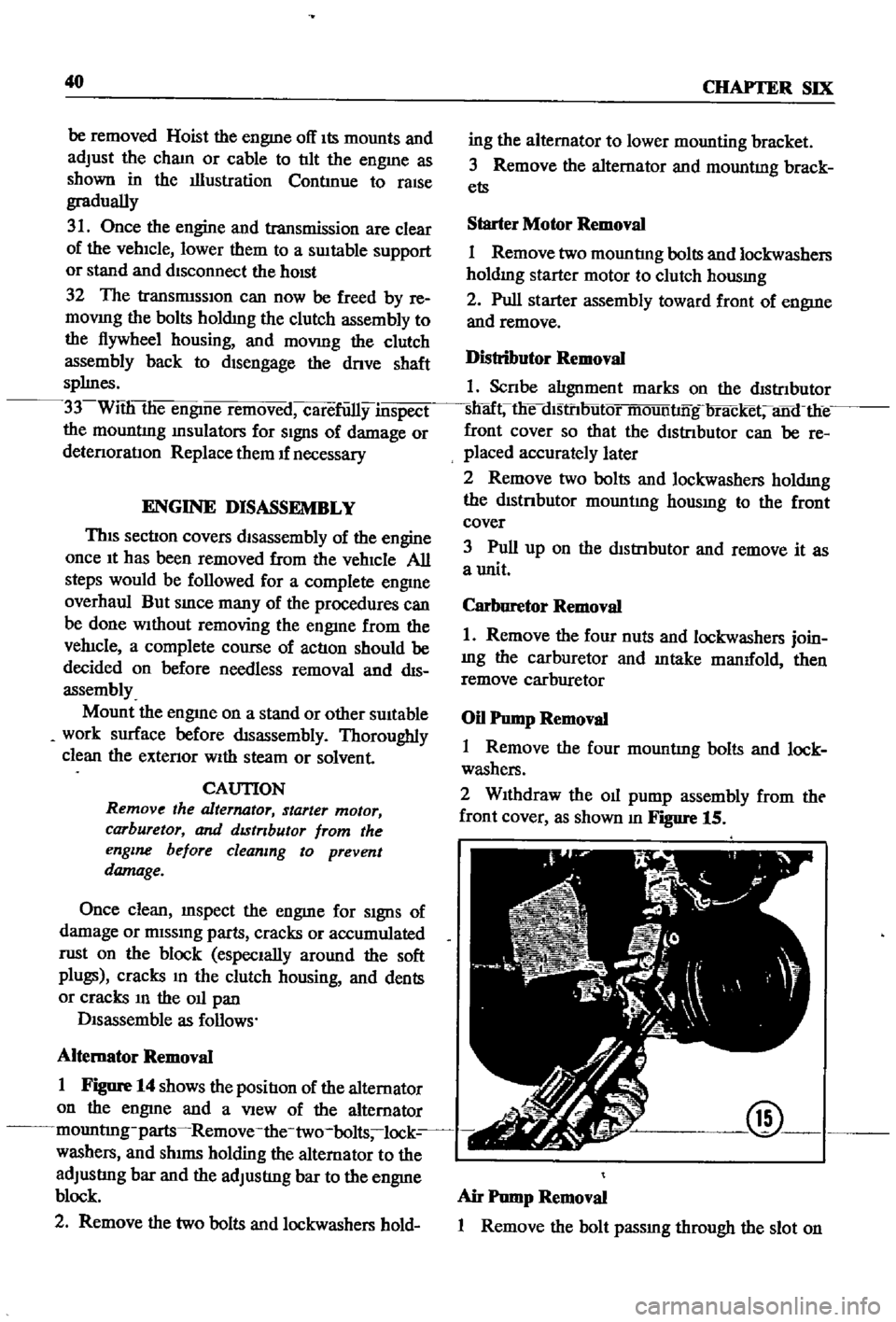
2
WIthdraw
the
011
pump
assembly
from
tht
front
cover
as
shown
m
Figure
15
@
Air
Pump
Removal
1
Remove
the
bolt
passmg
through
the
slot
on
Page 55 of 252
50
CHAPTER
SIX
3
Pull
up
on
the
spnng
scale
If
the
force
re
qurred
to
pull
the
feeler
gauge
out
IS
more
than
3
3
lbs
or
less
than
0
44
Ibs
the
piston
skirt
IS
either
too
large
or
small
for
the
cyhnder
and
must
be
replaced
With
a
pISton
of
the
proper
size
EIther
that
or
the
cyhnder
must
be
rebored
or
a
new
cyhnder
hner
mstalled
Piston
Piston
Pin
and
Piston
Ring
1
Inspect
all
parts
carefully
for
signs
of
clups
cracks
and
general
wear
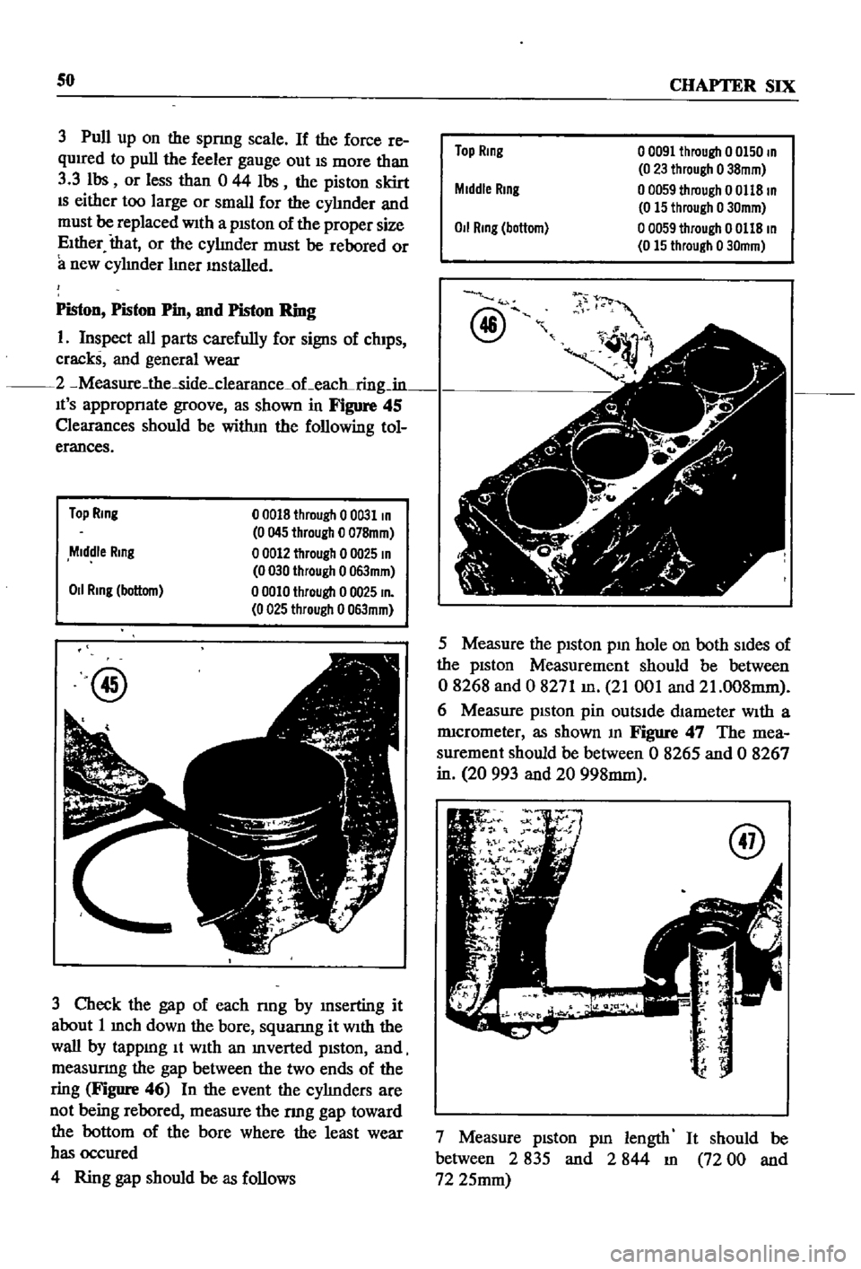
2
Measure
the
side
clearance
oLeac
ring
in
It
S
appropnate
groove
as
shown
in
Figure
45
Clearances
should
be
witlun
the
following
tol
erances
Top
Ring
00018
through
00031
In
0045
through
0
078mm
00012
through
0
0025
In
0030
through
0063mm
00010
through
0
0025
In
0025
through
0063mm
Middle
Ring
011
Ring
bottom
@
3
Check
the
gap
of
each
nng
by
mserting
it
about
1
mch
down
the
bore
squanng
it
With
the
wall
by
tappmg
It
WIth
an
mverted
pIston
and
measunng
the
gap
between
the
two
ends
of
the
ring
Figure
46
In
the
event
the
cyhnders
are
not
being
rebored
measure
the
nng
gap
toward
the
bottom
of
the
bore
where
the
least
wear
has
occured
4
Ring
gap
should
be
as
follows
Top
Ring
00091
through
0
0150
In
0
23
through
o
38mm
o
0059
through
0
0118
In
0
15
through
0
30mm
o
0059
through
0
0118
In
0
15
through
0
30mm
Middle
Rmg
0
1
Rmg
bottom
@
fJ
t
1
v
5
Measure
the
pIston
pm
hole
on
both
SIdes
of
the
pIston
Measurement
should
be
between
08268
and
0
8271
m
21
001
and
21
008mm
6
Measure
pISton
pin
outsIde
dIameter
With
a
nucrometer
as
shown
m
Figure
47
The
mea
surement
should
be
between
0
8265
and
0
8267
in
20
993
and
20
998mm
7
Measure
pIston
pm
length
It
should
be
between
2
835
and
2
844
m
72
00
and
72
25mm
Page 59 of 252
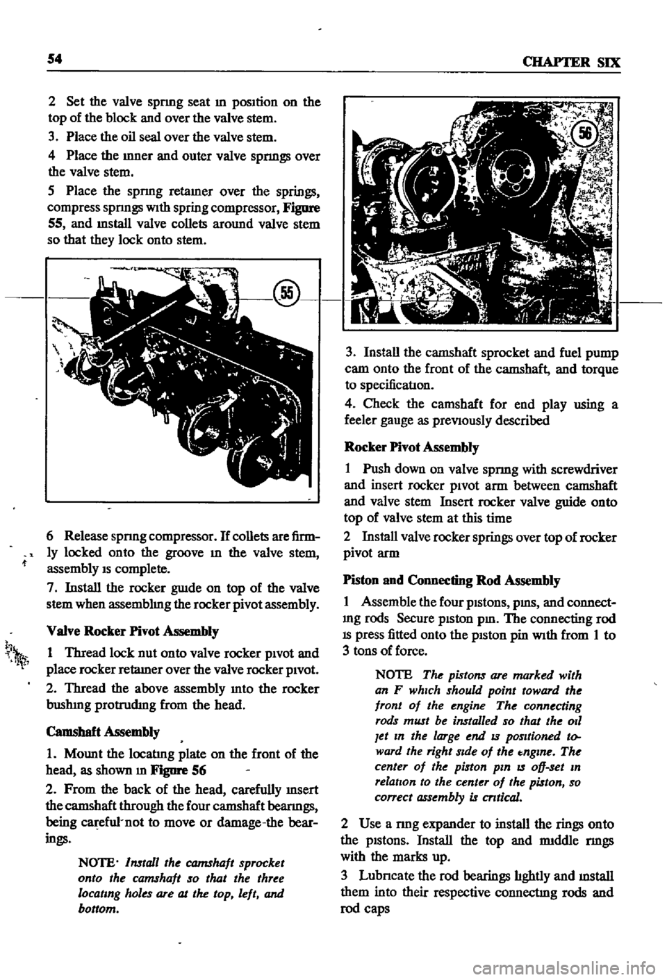
54
CHAP1ER
SIX
2
Set
the
valve
spnng
seat
m
position
on
the
top
of
the
block
and
over
the
valve
stem
3
Place
the
oil
seal
over
the
valve
stem
4
Place
the
mner
and
outer
valve
spnngs
over
the
valve
stem
S
Place
the
spnng
retamer
over
the
springs
compress
spnngs
With
spring
compressor
Figure
55
and
mstall
valve
collets
around
valve
stem
so
that
they
lock
onto
stem
6
Release
spnng
compressor
If
collets
are
firm
ly
locked
onto
the
groove
m
the
valve
stem
assembly
IS
complete
7
Install
the
rocker
guIde
on
top
of
the
valve
stem
when
assemblmg
the
rocker
pivot
assembly
VaIve
Rocker
Pivot
Assembly
1
Thread
lock
nut
onto
valve
rocker
pivOt
and
place
rocker
retaIner
over
the
valve
rocker
pivOt
2
Thread
the
above
assembly
mto
the
rocker
bushIng
protrudIng
from
the
head
Camshaft
Assembly
1
Mount
the
locatIng
plate
on
the
front
of
the
head
as
shown
m
FJgIlI
1
56
2
From
the
back
of
the
head
carefully
InSert
the
camshaft
through
the
four
camshaft
beanngs
being
ca
efu1
not
to
move
or
damage
the
bear
ings
NOTE
Install
the
CQJ7IShaft
sprocket
onto
the
camshaft
so
that
the
three
locating
holes
are
at
the
top
left
and
bottom
h
1
3
Install
the
camshaft
sprocket
and
fuel
pump
cam
onto
the
front
of
the
camshaft
and
torque
to
specificatIon
4
Check
the
camshaft
for
end
play
using
a
feeler
gauge
as
preViously
described
Rocker
Pivot
Assembly
1
Push
down
on
valve
spnng
with
screwdriver
and
insert
rocker
piVOt
arm
between
camshaft
and
valve
stem
Insert
rocker
valve
guide
onto
top
of
valve
stem
at
this
time
2
Install
valve
rocker
springs
over
top
of
rocker
pivot
arm
Piston
and
Connecting
Rod
Assembly
1
Assemble
the
four
pistons
pms
and
connect
mg
rods
Secure
piston
pm
The
connecting
rod
IS
press
fitted
onto
the
pISton
pin
With
from
1
to
3
tons
of
force
NOTE
The
pistons
are
marked
with
an
F
which
should
point
toward
the
front
of
the
engine
The
connecting
rods
must
be
installed
so
that
the
011
Jet
In
the
large
end
IS
positioned
to
ward
the
right
Side
of
the
tnglne
The
center
of
the
piston
pin
IS
oD
set
In
relation
to
the
center
of
the
piston
so
correct
assembly
is
cntical
2
Use
a
nng
expander
to
install
the
rings
onto
the
pistons
Install
the
top
and
rmddle
nngs
with
the
marks
up
3
Lubncate
the
rod
bearings
hghtly
and
mstall
them
into
their
respective
connectIng
rods
and
rod
caps
Page 60 of 252
ENGINE
55
Cylinder
Block
Assembly
1
PositIon
all
crankshaft
parts
on
a
work
bench
ThIS
mcludes
the
crankshaft
main
beanngs
rear
011
seal
woodruff
keys
crankshaft
gear
011
pump
gear
011
thrower
bolts
and
bearing
caps
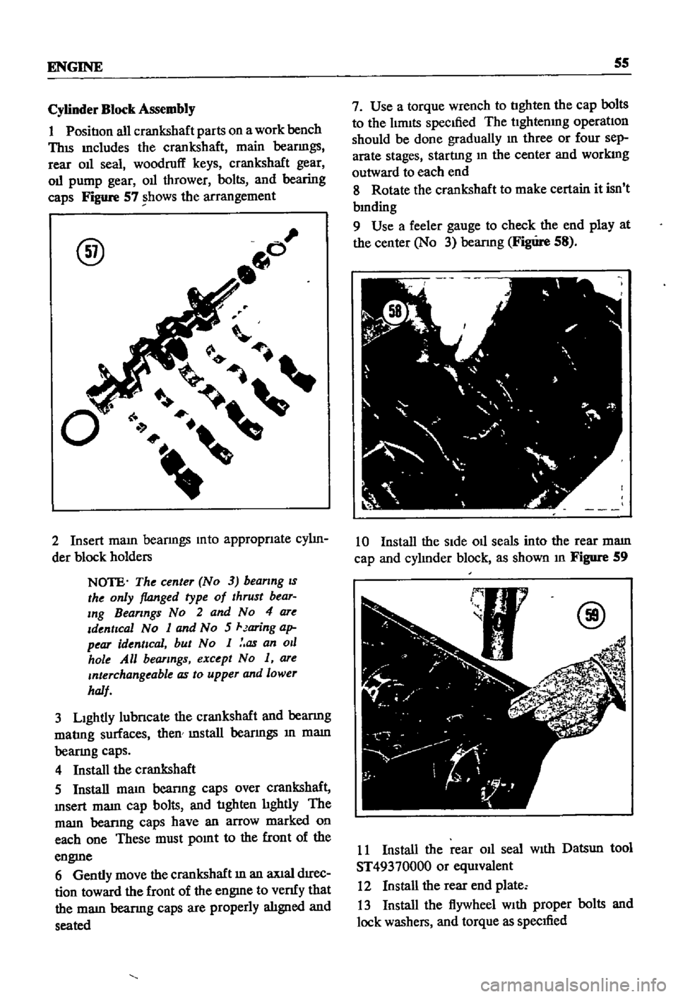
Figure
57
shows
the
arrangement
@
2
Insert
maIO
beanngs
mto
appropnate
cy1m
der
block
holders
NOTE
The
center
No
3
beanng
IS
the
only
flanged
type
of
thrust
bear
Ing
Bearings
No
2
and
No
4
are
Identical
No
1
and
No
5
Jaring
ap
pear
identical
but
No
1
as
an
011
hole
All
bearings
except
No
1
are
Interchangeable
as
to
upper
and
lower
half
3
LIghtly
lubncate
the
crankshaft
and
beanng
matmg
surfaces
then
mstall
beanngs
10
mam
beanng
caps
4
Install
the
crankshaft
5
Install
mam
beanng
caps
over
crankshaft
msert
mam
cap
bolts
and
tighten
hghtly
The
mam
beanng
caps
have
an
arrow
marked
on
each
one
These
must
pomt
to
the
front
of
the
engme
6
Gently
move
the
crankshaft
10
an
aXIal
drrec
don
toward
the
front
of
the
engme
to
venfy
that
the
mam
beanng
caps
are
properly
alIgned
and
seated
7
Use
a
torque
wrench
to
tighten
the
cap
bolts
to
the
hmlts
speCIfied
The
t1ghtenmg
operatIon
should
be
done
gradually
10
three
or
four
sep
arate
stages
starting
10
the
center
and
workmg
outward
to
each
end
8
Rotate
the
crankshaft
to
make
certain
it
isn
t
bmding
9
Use
a
feeler
gauge
to
check
the
end
play
at
the
center
No
3
beanng
Figure
58
10
Install
the
SIde
oll
seals
into
the
rear
mam
cap
and
cy1mder
block
as
shown
10
Figure
59
@
11
Install
the
rear
011
seal
WIth
Datsun
tool
ST49370000
or
equIvalent
12
Install
the
rear
end
plate
13
Install
the
flywheel
WIth
proper
bolts
and
lock
washers
and
torque
as
specified
Page 63 of 252
58
CHAPTER
SIX
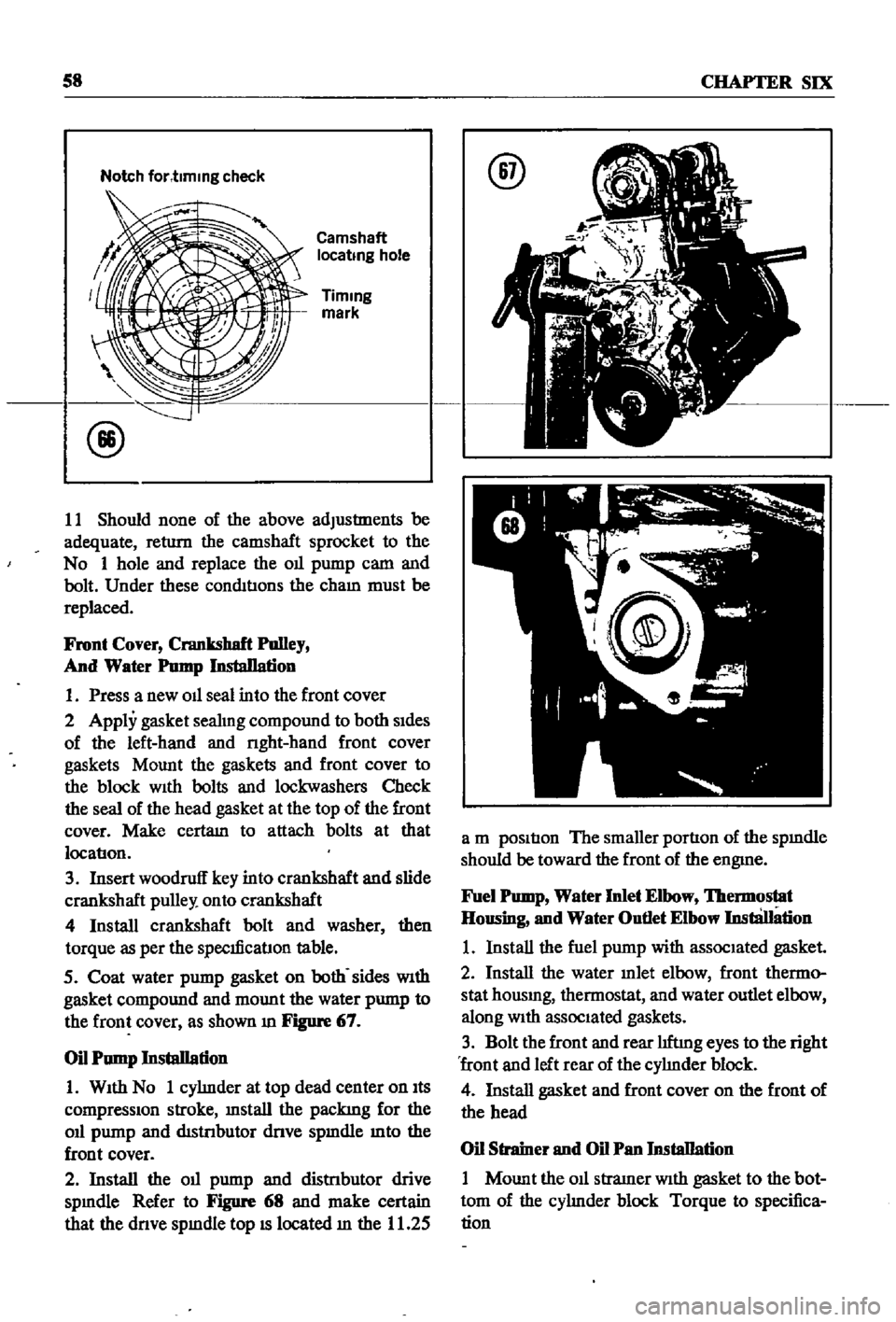
Notch
for
t1mmg
check
Camshaft
locatmg
hole
Timmg
mark
11
Should
none
of
the
above
adjustments
be
adequate
return
the
camshaft
sprocket
to
the
No
1
hole
and
replace
the
Oll
pump
cam
and
bolt
Under
these
conditIons
the
cham
must
be
replaced
Front
Cover
Crankshaft
Polley
And
Water
Pomp
InstaDation
1
Press
a
new
Oll
seal
into
the
front
cover
2
Apply
gasket
seahng
compound
to
both
sides
of
the
left
hand
and
nght
hand
front
cover
gaskets
Mount
the
gaskets
and
front
cover
to
the
block
With
bolts
and
lockwashers
Check
the
seal
of
the
head
gasket
at
the
top
of
the
front
cover
Make
certam
to
attach
bolts
at
that
locatlon
3
Insert
woodruff
key
into
crankshaft
and
slide
crankshaft
pulley
onto
crankshaft
4
Install
crankshaft
bolt
and
washer
then
torque
as
per
the
speclficatlon
table
5
Coat
water
pump
gasket
on
both
sides
With
gasket
compound
and
mount
the
water
pump
to
the
front
cover
as
shown
m
Figure
67
Oil
Pump
Installation
1
With
No
1
cyhnder
at
top
dead
center
on
Its
compressIOn
stroke
mstall
the
packing
for
the
Oll
pump
and
distnbutor
dnve
spmdle
mto
the
front
cover
2
Install
the
Oll
pump
and
distnbutor
drive
spmdle
Refer
to
Figure
68
and
make
certain
that
the
dnve
spmdle
top
IS
located
m
the
11
25
@
a
m
position
The
smaller
portion
of
the
spmdle
should
be
toward
the
front
of
the
engme
Fuel
Pomp
Water
Inlet
Elbow
lbermostat
Housing
and
Water
Outlet
Elbow
InstliJIation
1
Install
the
fuel
pump
with
associated
gasket
2
Install
the
water
mlet
elbow
front
thermo
stat
housmg
thermostat
and
water
outlet
elbow
along
With
associated
gaskets
3
Bolt
the
front
and
rear
hftmg
eyes
to
the
right
front
and
left
rear
of
the
cyhnder
block
4
Install
gasket
and
front
cover
on
the
front
of
the
head
Oil
Strainer
and
Oil
Pan
Installation
1
Mount
the
011
stramer
With
gasket
to
the
bot
tom
of
the
cyhnder
block
Torque
to
specifica
tion
Page 64 of 252
ENGINE
59
2
Coat
the
pan
gasket
on
both
sides
With
gasket
compound
and
attach
the
oil
pan
to
the
cyhnder
block
Torque
as
specIfied
Manifold
and
Carburetor
Installation
1
Install
the
mtake
and
exhaust
manIfolds
WIth
associated
gasket
to
the
cylmder
head
2
Mount
the
carburetor
and
gasket
to
the
mtake
manIfold
2
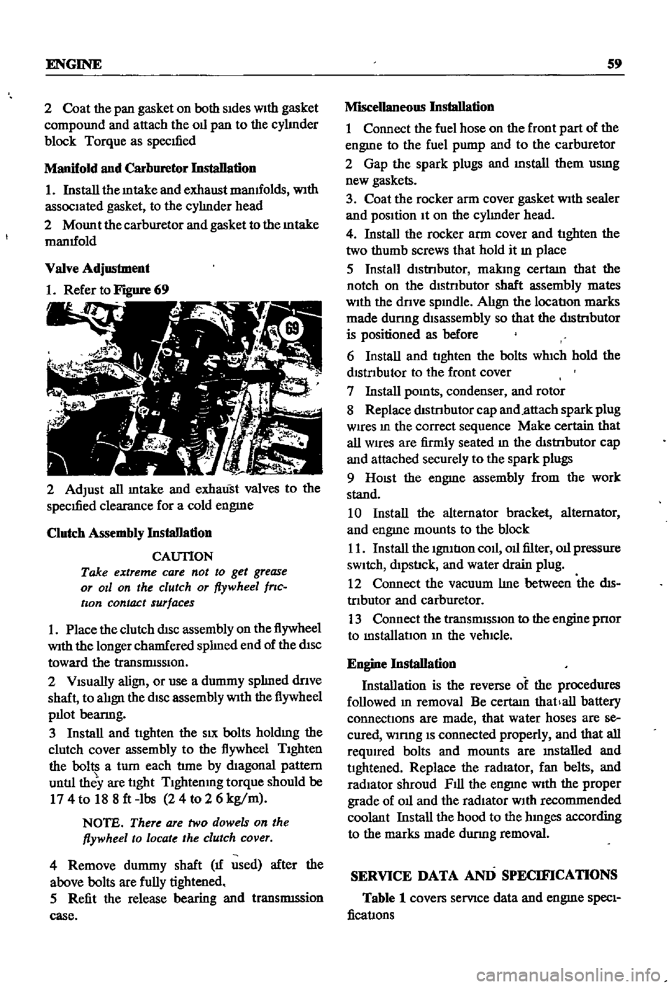
Adjust
all
mtake
and
exhaust
valves
to
the
specIfied
clearance
for
a
cold
engme
Clutch
Assembly
Installation
CAUTION
Take
extreme
care
not
to
get
grease
or
011
on
the
clutch
or
flywheel
frlc
hon
contact
surfaces
1
Place
the
clutch
disc
assembly
on
the
flywheel
With
the
longer
chamfered
splmed
end
of
the
dISC
toward
the
transmISSion
2
Visually
align
or
use
a
dummy
splmed
dnve
shaft
to
ahgn
the
diSC
assembly
With
the
flywheel
pilot
beanng
3
Install
and
tighten
the
SIX
bolts
holdmg
the
clutch
cover
assembly
to
the
flywheel
Tighten
the
bolts
a
turn
each
tune
by
diagonal
pattern
until
they
are
tight
Tlghtenmg
torque
should
be
174
to
188ft
lbs
24
to
2
6
kg
m
NOTE
There
are
two
dowels
on
the
flywheel
to
locate
the
clutch
cover
4
Remove
dummy
shaft
If
used
after
the
above
bolts
are
fully
tightened
5
Refit
the
release
bearing
and
translI11Ssion
case
Miscellaneous
Installation
1
Connect
the
fuel
hose
on
the
front
part
of
the
engme
to
the
fuel
pump
and
to
the
carburetor
2
Gap
the
spark
plugs
and
mstall
them
usmg
new
gaskets
3
Coat
the
rocker
arm
cover
gasket
With
sealer
and
position
It
on
the
cylmder
head
4
Install
the
rocker
arm
cover
and
tighten
the
two
thumb
screws
that
hold
it
m
place
5
Install
distrIbutor
makmg
certam
that
the
notch
on
the
distributor
shaft
assembly
mates
With
the
drive
spmdle
Ahgn
the
location
marks
made
dunng
disassembly
so
that
the
distrIbutor
is
positioned
as
before
6
Install
and
tighten
the
bolts
which
hold
the
dIStributor
to
the
front
cover
7
Install
pomts
condenser
and
rotor
8
Replace
distrIbutor
cap
and
attach
spark
plug
Wires
m
the
correct
sequence
Make
certain
that
all
wires
are
firmly
seated
m
the
distrIbutor
cap
and
attached
securely
to
the
spark
plugs
9
HOISt
the
engme
assembly
from
the
work
stand
10
Install
the
alternator
bracket
alternator
and
engme
mounts
to
the
block
11
Install
the
IgnItIon
coil
oil
filter
oil
pressure
SWitch
dipstick
and
water
drain
plug
12
Connect
the
vacuum
Ime
between
the
dis
trIbutor
and
carburetor
13
Connect
the
transIDlSSlOn
to
the
engine
prior
to
mstallatIon
m
the
vehicle
Engine
Installation
Installation
is
the
reverse
of
the
procedures
followed
m
removal
Be
certaIn
thatlall
battery
connections
are
made
that
water
hoses
are
se
cured
wmng
IS
connected
properly
and
that
all
required
bolts
and
mounts
are
mstalled
and
tightened
Replace
the
radiator
fan
belts
and
radiator
shroud
Fill
the
engme
With
the
proper
grade
of
oil
and
the
radiator
With
recommended
coolant
Install
the
hood
to
the
hInges
according
to
the
marks
made
dUrIng
removal
SERVICE
DATA
AND
SPECIFICATIONS
Table
1
covers
servIce
data
and
engme
Speci
fications
Page 90 of 252
COOLING
SYSTEM
8S
and
In
those
with
exhaust
and
evaporatIve
emIS
sion
control
devIces
a
fan
clutch
IS
combIned
WIth
the
thermostat
to
detect
temperature
m
the
engme
compartlnent
When
the
temperature
nses
the
thermostat
detects
the
change
an
the
fan
clutch
engages
thereby
helpmg
to
cool
the
engme
WATER
PUMP
Figure
2
page
86
IS
an
exploded
drawmg
of
the
water
pump
and
fan
assembly
for
1970
to
1971
The
top
half
of
the
IllustratIon
applIes
to
those
models
WIth
exhaust
and
evaporatIve
emiSSIOn
control
systems
The
bottom
half
covers
models
WIth
a
crankcase
emiSSIon
control
deVIce
only
Figure
3
page
87
IS
an
exploded
drawmg
of
the
water
pump
and
fan
assembly
for
1968
models
Without
exhaust
or
evaporatIve
controls
Figure
4
page
88
shows
the
1968
model
With
emISSIon
control
deVIce
As
can
be
seen
from
the
illustratIons
most
dIfferences
eXISt
withIn
the
fan
clutch
assembly
Water
Pump
Removal
1
Remove
upper
and
lower
radIator
hoses
from
the
thermostat
housmg
and
cylmder
block
re
spectIvely
Dram
coolant
from
rad1ator
and
cylInder
block
2
Loosen
the
alternator
mountlng
bolt
and
the
adjustIng
bolt
on
the
alternator
mountIng
bracket
3
Move
the
alternator
toward
the
cylinder
block
untIl
slack
IS
eVIdent
10
the
fan
belt
Re
move
fa
belt
fro
alternator
water
pump
and
crankshaft
pulley
4
It
IS
difficult
to
remove
the
water
pump
from
the
front
housmg
With
the
radiator
and
top
shroud
10
place
so
remove
them
5
Remove
the
bolts
holdmg
the
fan
assembly
to
the
water
pump
and
remove
the
fan
assembly
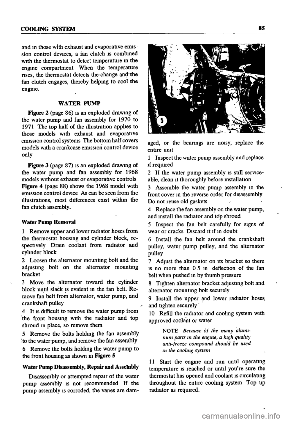
6
Remove
the
bolts
holdmg
the
water
pump
to
the
front
housmg
as
shown
In
Figure
S
Water
Pump
Disassembly
Repair
and
Assembly
Disassembly
or
attempted
repaIr
of
the
water
pump
assembly
IS
not
recommended
If
the
pump
assembly
IS
corroded
the
vanes
are
dam
aged
or
the
bearmgs
are
nOISY
replace
the
entIre
umt
1
Inspect
the
water
pump
assembly
and
replace
If
reqUIred
2
If
the
water
pump
assembly
IS
stIll
serVIce
able
clean
It
thoroughly
before
mstallatIon
3
Assemble
the
water
pump
assembly
m
the
front
cover
10
the
reverse
order
for
disassembly
Do
not
reuse
old
gaskets
4
Replace
the
fan
assembly
on
the
water
pump
and
mstall
the
radiator
and
top
shroud
5
Inspect
the
fan
belt
carefully
for
SIgnS
of
wear
or
cracks
DIscard
It
If
10
doubt
6
Install
the
fan
belt
around
the
crankshaft
pulley
water
pump
pulley
and
the
alternator
pulley
7
Adjust
the
alternator
on
Its
bracket
so
there
IS
no
more
than
0
5
10
deflection
of
the
fan
belt
when
pushed
10
by
thumb
pressure
8
TIghten
alternator
bracket
adjustIng
bolt
and
alternator
mountmg
bolt
securely
9
Install
the
upper
and
lower
rad1ator
hoses
and
tIghten
securely
10
Refill
the
radIator
and
coolmg
system
With
approved
coolant
or
water
NOTE
Because
of
the
many
aluml
num
parts
In
the
engine
a
hIgh
qualIty
antI
freeze
compound
should
be
used
In
the
cooling
system
11
Start
the
engme
and
run
untIl
operatIng
temperature
IS
reached
or
untIl
you
re
sure
the
thermostat
has
opened
and
coolant
IS
CIrCulatIng
throughout
the
entIre
coolIng
system
Top
up
radIator
as
reqUIred
Page 97 of 252

91
CHAPTER
NINE
bon
the
serIes
coll
demagnetizes
agatnst
the
shunt
cOIl
The
return
spnng
causes
the
plunger
to
return
to
the
origmal
posItIon
stoppmg
the
starter
The
overrunnmg
clutch
provIdes
for
positIve
meshmg
and
unmeshmg
of
the
pmlOn
gear
and
flywheerrmg
gear
and
perinitStlie
pmlon
to
overrun
the
armature
after
the
engme
has
started
CONSTRUCIlON
A
typical
Datsun
starter
motor
is
shown
m
Figure
3
The
example
is
for
1971
models
but
about
the
only
dIfferences
existing
between
It
and
other
models
are
the
number
of
elements
used
in
the
dust
cover
and
the
number
of
thrust
washers
Removal
1
DIsconnect
the
battery
ground
cable
2
Disconnect
the
black
yellow
wire
from
the
magnetIc
sWitch
tennmal
on
the
solenoid
3
Disconnect
the
black
battery
cable
and
red
wire
from
the
battery
tennmal
on
the
solenOId
4
Remove
two
bolts
holdmg
the
startmg
motor
to
flywheel
hOUSIng
The
battery
ground
cable
is
attached
to
the
flywheel
hOUSIng
bottom
bolt
5
Pull
starter
motor
toward
front
of
engme
and
remove
Disassembly
1
Remove
the
nut
holdIng
the
electrIc
WIre
to
the
magnetIc
sWItch
M
tennmal
DIsconnect
the
WIre
2
Remove
three
screws
securmg
magnetic
switch
assembly
to
yoke
Remove
magnetic
sWItch
assembly
and
dust
cover
s
Figure
4
3
Remove
two
through
bolts
and
brush
cover
assembly
as
shown
m
Figure
5
4
Remove
the
yoke
assembly
by
tappmg
lIghtly
as
In
Figure
6
5
Remove
bolt
nut
and
washers
at
base
of
yoke
to
free
shut
lever
WIthdraw
the
armatlIre
and
shut
lever
as
shown
m
Figure
7
6
Remove
the
pInIOn
stop
nng
located
at
the
end
of
the
armature
shaft
To
remove
the
stop
nng
push
the
stop
nng
to
the
clutch
SIde
remove
the
snap
nng
and
Withdraw
the
stop
nng
and
CD
c
0
I
CD
Ml
ml
CD
a
I
II
0
l
g
I
o