brake light DATSUN 510 1969 Service Repair Manual
[x] Cancel search | Manufacturer: DATSUN, Model Year: 1969, Model line: 510, Model: DATSUN 510 1969Pages: 171, PDF Size: 10.63 MB
Page 6 of 171
EngIne
INTRODUCTION
ENGINE
Removal
ENGINE
DismantUng
ENGINE
Inspection
and
Overhaul
VALVES
VALVE
GUIDES
VALVE
SEAT
INSERTS
CAMSHAFT
AND
CAMSHAFT
BEARINGS
Checking
CYliNDER
BLOCK
PtSTONS
AND
CONNECTING
RODS
INTRODUCTION
The
1400
1600
cc
and
1800
cc
engines
are
four
cylinder
in
line
units
with
a
single
overhead
camshaft
and
fully
balanced
five
bearing
crankshaft
The
valves
are
operated
through
rockers
which
are
directly
activated
by
the
earn
mechanism
The
crankshaft
is
a
special
steel
forging
with
the
centre
main
bearing
equipped
with
thrust
washers
to
take
up
the
end
thrust
of
the
crankshaft
The
special
aluminium
pistons
are
of
the
strut
construction
to
control
thermal
expansion
and
have
two
compression
rings
and
one
combined
oil
ring
The
gudgeon
pins
have
special
hollow
steel
shafts
and
are
a
fully
floating
fit
in
the
pistons
and
a
press
fit
in
the
connecting
rods
The
aluminium
alloy
cylinder
head
contains
wedge
type
combustion
chambers
and
is
fitted
with
aluminium
bronze
valve
seats
for
the
intake
valves
and
heat
resistant
steel
valve
seats
for
the
exhaust
valves
The
cast
iron
camshaft
is
driven
by
a
double
row
roller
chain
from
the
crankshaft
pulley
The
engine
is
pressure
lubricated
by
a
rotor
type
oil
pump
which
draws
oil
through
an
oil
strainer
into
the
pump
housing
and
then
forces
it
through
a
full
flow
oil
filter
into
the
main
oil
gallery
ENGINE
Removal
Place
alignment
marks
on
the
bonnet
and
hinges
remove
the
bonnet
from
the
vehicle
2
Drain
the
cooling
system
and
engine
and
transmission
lubricant
Remove
the
radiator
grille
3
Discon
ect
the
battery
cables
and
lift
out
the
battery
4
Detach
the
upper
and
lower
radiator
hoses
remove
the
radiator
mounting
bolts
and
lift
the
radiator
away
from
the
vehicle
The
torque
converter
c
jng
pipes
must
be
disconnected
from
the
radiator
on
vehicles
fitted
with
automatic
transmission
S
Remove
the
COOling
fan
and
pulley
disconnect
the
fuel
pipe
from
the
fuel
pump
and
the
heater
hoses
from
the
engine
attachments
6
Disconnect
the
accelerator
control
linkage
and
the
choke
CRANKSHAFT
AND
MAIN
BEARINGS
CAMSHAFT
AND
SPROCKET
FLYWHEEL
ENGINE
Assembling
VALVE
CLEARANCES
Adjusting
ENGINE
LUBRICATION
SYSTEM
OIL
PUMP
OIL
FILTER
CHANGING
THE
ENGINE
OIL
cable
from
the
carburettor
7
Disconnect
the
wirings
from
the
starter
alternator
ignition
coil
oil
pressure
switch
and
temperature
sender
unit
8
Remove
the
clutch
slave
cylinder
Fig
A
2
and
its
return
spring
9
Disconnect
the
speedometer
cable
and
withdraw
the
plug
connector
from
the
reversing
light
switch
10
Disconnect
the
shift
rods
and
seJector
rods
and
remove
the
cross
shaft
assembly
as
described
in
the
section
Gear
box
II
Disconnect
the
front
exhaust
pipe
from
the
exhaust
manifold
disconnect
the
centre
pipe
from
the
rear
pipe
and
remove
the
front
pipe
pre
muffler
and
centre
pipe
assembly
12
Disconnect
the
propeUer
shaft
flange
from
the
companion
flange
from
the
gear
carrier
13
Jack
up
the
gearbox
slightly
and
remove
the
rear
engine
mounting
bracket
bolts
remove
the
mounting
cross
member
and
handbrake
cable
c1amp
14
Remove
the
bolts
securing
the
front
engine
mounting
brackets
to
the
crossmember
15
Attach
lifting
cable
or
chains
to
the
hooks
installed
at
the
front
and
rear
of
the
cylinder
head
Lower
the
jack
under
the
gearbox
and
carefully
lift
and
tilt
the
engine
and
gearbox
unit
Withdraw
the
engine
and
gearbox
from
the
compartment
making
sure
that
it
is
guided
past
the
accessories
installed
on
the
body
ENGINE
Dismantling
Remove
the
engine
as
previously
described
and
carefully
clean
the
exterior
surfaces
Cbeck
for
signs
of
fuel
oil
or
water
leaks
past
the
cylinder
head
and
block
Remove
the
air
cleaner
alternator
distributor
and
starter
motor
Plug
the
carburettor
air
horn
and
distributor
hole
to
prevent
the
ingress
of
foreign
matter
Remove
the
gearbox
from
the
engine
drain
the
engine
oil
and
coolant
Mount
the
engine
in
a
suitable
stand
the
special
engine
attachment
ST05260001
and
engine
ST0501SOO0
should
be
used
if
available
Fig
A
3
5
Page 84 of 171
Front
SuspensIon
DESCRIPTION
WHEEL
HUBS
WHEEL
BEARINGS
Adjusting
FRONT
AXLE
AND
SUSPENSION
ASSEMBLY
DESCRIPTION
The
front
suspension
is
of
the
strut
type
with
the
coil
spring
and
hydraulic
damper
units
mounted
on
the
suspension
member
and
transverse
link
assembly
See
FigJ
1
Vertical
movement
of
the
suspension
is
controlled
by
the
strut
assembly
the
tension
rod
absorbs
the
forward
and
backward
movement
of
the
transverse
links
whilst
side
move
ment
of
the
body
is
controlled
by
the
stabilizer
rod
which
is
attached
to
the
body
and
transverse
links
WHEEL
HUBS
Removal
1
Jack
up
the
vehicle
remove
the
road
wheel
and
disconnect
the
brake
hose
at
the
strut
outer
casing
bracket
as
described
under
the
previous
heading
Plug
the
opened
end
of
the
hose
to
prevent
loss
of
fluid
2
Remove
the
brake
calliper
assembly
or
the
brake
drum
as
described
in
the
section
BRAKES
3
Remove
the
grease
cap
from
the
hub
by
tapping
lightly
at
the
joint
using
a
screwdriver
and
hammer
4
Withdraw
the
cotter
pin
from
the
wheel
bearing
locknut
and
remove
the
nut
Remove
the
wheel
hub
together
with
the
wheel
bearing
and
washer
Fig
J
2
On
cars
fitted
with
disc
brakes
the
hub
is
removed
complete
with
brake
disc
5
The
wheel
bearing
outer
race
can
be
removed
from
the
hub
using
a
drift
as
shown
in
Fig
I
3
WHEEL
HUBS
Inspection
and
Overhaul
Gean
the
hub
and
bearings
by
washing
in
petrol
Examine
the
grease
seal
and
make
sure
that
it
is
not
worn
or
cracked
renew
the
seal
if
necessary
Ensure
that
the
races
are
not
pitted
or
scored
rotate
them
and
check
for
signs
of
wear
and
play
A
sectional
view
of
the
wheel
bearing
assembly
is
given
in
Fig
14
to
provide
an
indication
of
the
points
to
be
checked
WHEEL
HUB
AND
BEARING
Installation
The
wheel
bearing
outer
race
can
be
refitted
with
a
suitable
drift
or
special
tool
ST
35310000
Fill
the
wheel
hub
and
the
hub
cap
to
the
positions
shown
in
Fig
J
5
with
multi
purpose
grease
Fill
the
spaces
between
the
bearing
rollers
and
the
lip
of
the
grease
seal
with
the
same
type
of
grease
Lightly
smear
the
spindle
shaft
and
threads
the
bearing
washer
and
bearing
lock
SPRING
AND
STRUT
ASSEMBLY
TRANSVERSE
LINK
AND
LOWER
BALL
JOINT
FRONT
WHEEL
ALIGNMENT
ADJUSTING
THE
STEERING
ANGLE
nut
with
grease
and
assemble
the
parts
onto
the
wheel
spindle
Make
sure
that
dirt
and
foreign
matter
does
not
adhere
to
the
greased
surfaces
Adjust
the
wheel
bearings
as
described
under
the
following
heading
WHEEL
BEARINGS
Adjusting
The
wheel
bearings
can
be
adjusted
with
the
road
wheel
the
hub
cap
and
the
bearing
locknut
cotterpin
removed
as
previously
described
Tighten
the
wheel
bearing
locknut
to
a
torque
reading
of
3
0
3
5
kgm
21
7
25
3lb
ft
Turn
the
hub
several
times
in
each
direction
to
settle
the
bearing
and
then
retighten
the
bearing
locknut
to
the
specified
torque
reading
Slacken
the
bearing
locknut
to
an
angle
between
40
to
700
a
ay
from
the
previously
tightened
position
and
align
the
cotter
pin
hole
with
the
hole
in
the
spindle
Turn
the
wheel
hub
a
few
times
in
each
direction
and
then
measure
the
torque
required
to
cause
the
hub
to
turlI
A
spring
balance
should
be
used
as
shown
m
Rig
J
p
make
sure
that
the
brake
pads
are
not
binding
on
the
disc
type
of
brake
unit
and
check
that
the
force
required
to
turn
the
hub
is
within
the
following
fIgures
Wheel
bearing
rotation
starting
torque
1800ce
With
new
bearing
7
0
kg
cm
97
in
oz
1400
1600cc
With
new
bearing
8
0
kg
cm
111
2
in
oz
With
used
bearing
4
0
kg
cm
56
0
in
oz
Starting
torque
at
the
hub
bolt
lWth
new
bearing
ith
used
bearings
1
57
kg
3
46
lb
0
7
kg
1
541b
Adjust
the
locknut
slightly
if
the
fIgures
do
not
conform
and
replace
the
cotterpin
Refit
the
hub
cap
and
the
road
wheel
FRONT
AXLE
AND
SUSPENSION
ASSEMBLY
Removal
Jack
up
the
front
of
the
vehicle
and
place
stands
under
the
ront
side
members
Remove
the
road
wheels
and
the
splash
board
3
Disconnect
the
front
brake
hoses
and
remove
the
brake
hose
locking
springs
Withdraw
the
plates
and
remove
the
hoses
from
the
strut
assembly
Plug
the
ends
of
the
hoses
to
prevent
the
ingress
of
dirt
and
loss
of
fluid
4
Remove
the
cotter
pin
from
the
tie
rod
ball
joint
remove
83
Page 88 of 171
the
castle
nut
and
detach
the
tie
rod
from
the
knuckle
arm
5
Remove
the
tension
rod
securing
nuts
Fig
J
7
remove
the
bolts
and
withdraw
the
tension
rod
Withdraw
the
nut
shown
arrowed
in
FigJ
8
and
remove
the
stabilizer
6
Support
the
engine
with
suitable
lifting
tackle
so
that
the
engine
mounting
bolts
can
be
removed
and
the
suspension
crossmember
detached
from
the
engine
FigJ
9
7
Place
ajack
under
the
crossmember
Remove
the
bolts
indicated
in
Fig
J
IO
and
separate
the
crossmember
from
the
body
8
Remove
the
strut
assembly
upper
attachment
self
locking
nuts
at
both
sides
Fig
J
ll
and
lower
the
front
suspension
assembly
to
remove
it
from
the
vehicle
FRONT
AXLE
AND
SUSPENSION
ASSEMBLY
Installation
Installation
is
a
reversal
of
the
removal
procedure
noting
the
following
points
Make
sure
that
all
rubber
parts
are
free
from
wear
and
deterioration
Any
part
of
the
suspension
assembly
which
has
been
damaged
or
distorted
must
be
replaced
The
front
wheel
alignment
should
be
checked
after
completing
the
installation
a
brief
description
is
given
at
the
end
of
this
section
Camber
and
castor
angles
are
preset
and
cannot
be
adjusted
SPRING
AND
STRUf
ASSEMBLY
Removal
and
Installation
The
strut
assembly
consists
of
the
outer
casing
piston
rod
piston
rod
guide
and
cylinder
etc
An
exploded
view
of
the
components
is
given
in
Fig
J
12
The
inner
components
must
be
replaced
as
a
complete
assembly
Replacement
and
overhaul
procedures
for
the
inner
components
together
with
the
removal
of
the
front
springs
should
only
be
carried
out
by
a
specialist
Datsun
workshop
The
strut
assembly
can
be
removed
prior
to
dismantling
by
following
the
procedures
outlined
below
Jack
up
the
front
of
the
vehicle
and
support
it
on
stands
2
Disconnect
the
brake
hose
from
the
strut
assembly
bracket
as
previously
described
under
the
heading
FRONT
AXLE
and
SUSPENSION
ASSEMBLY
Removal
3
Remove
the
stabilizer
bar
and
tension
rod
from
the
trans
verse
links
Loosen
and
remove
the
knuckle
arm
fixing
bolts
Fig
J
9
And
separate
the
strut
assembly
from
the
ball
joints
4
Remove
the
strut
assembly
upper
attachment
self
locking
nuts
Fig
J
11
and
withdraw
the
strut
assembly
from
the
body
Fig
J
13
Installation
is
a
reversal
of
the
removal
procedure
Ensure
that
the
bolts
are
tightened
to
the
specified
torque
readings
given
under
TIGHTENING
TORQUES
SPRING
AND
STRUT
ASSEMBLY
Dismantling
and
Assembly
Care
must
be
taken
when
dismantling
the
assembly
to
ensure
that
aU
parts
are
maintained
in
a
clean
condition
Clamp
the
suspension
strut
assembly
in
a
vice
and
fit
the
special
attachment
ST
2770000
I
to
the
lower
end
of
the
strut
Prise
off
the
dust
cover
snap
ring
Use
the
coil
spring
compressor
ST
35650001
to
slightly
compress
the
spring
Remove
the
self
locking
nut
and
take
off
the
mounting
insulator
thrust
bearing
spring
seat
and
bump
rubber
Slacken
the
spring
compressor
and
remove
the
spring
Push
down
the
shock
absorber
piston
until
it
bottoms
and
remove
the
gland
packing
with
the
special
tool
ST
35500001
Fig
J
14
Remove
the
O
ring
from
the
piston
rod
guide
and
lift
out
the
piston
rod
and
cy
linder
assembly
00
NOT
separate
the
piston
and
cylinder
which
are
serviced
as
a
complete
assembly
Drain
all
fluid
from
the
suspension
unit
and
shock
absorber
assembly
Wash
all
parts
thoroughly
not
rubber
parts
in
petrol
or
a
suitable
solvent
The
gland
packing
and
0
ring
must
be
renewed
at
each
overhaul
Always
refill
with
the
correct
grade
of
fresh
oil
in
accordance
with
the
information
in
the
table
below
ATSUGI
KAYABA
Part
No
54302
UO
100
UOl10
325
cc
332
cc
54302
3
U0500
1
54302
N
1200
325
cc
300
cc
The
oil
quantity
is
extremely
critical
as
it
will
affect
the
damping
power
of
the
shock
absorber
To
assemble
fit
the
rubber
O
ring
on
the
top
of
the
piston
rod
and
refit
the
gland
packing
Take
care
that
the
oil
seal
does
not
become
damaged
during
the
latter
operation
Lift
the
piston
rod
up
by
approximately
90
mm
3
5
in
before
tightening
the
gland
packing
to
facilitate
bleeding
then
tighten
the
packing
to
a
torque
reading
of
7
13
kgm
51
94Jb
ft
Bleed
the
shock
absorber
by
pumping
the
piston
rod
up
and
down
until
the
pressure
is
the
same
in
both
directions
Position
the
coil
spring
bump
rubber
spring
seat
and
dust
cover
on
the
top
of
the
piston
rod
The
piston
rod
must
be
in
the
fully
extended
position
Compress
the
spring
fit
the
strut
mounting
insulator
and
bearing
assembly
Tighten
the
self
locking
nut
to
a
torque
reading
of
6
7
5
kgm
43
541b
ft
SPRING
AND
STRUT
ASSEMBLY
Installation
Installation
is
a
reversal
of
the
removal
procedure
Thoroughly
grease
the
parts
marked
in
Fig
J
15
Tighten
the
fixing
bolts
to
the
torque
readings
given
in
TIGHfENING
TORQUES
TRANSVERSE
LINK
AND
LOWER
BALL
JOINT
Removal
The
transverse
link
with
rubber
bushing
is
connected
to
the
suspension
crosSlTIember
by
a
mounting
bolt
as
shown
in
Fig
J
11
and
to
the
strut
assembly
via
the
lower
ball
joint
87
Page 99 of 171
inter
G
@lfi
r
OIl
ll
V
V
1
Re
rvoir
azp
2
Resovoir
tank
3
condDry
piston
rrtrun
rprins
4
Secondary
pitton
5
Primary
piston
tum
spring
6
Primary
piston
7
uvd
gau
Fl
L
I
Tandem
master
cylinder
level
gauge
on
SSS
models
only
Fig
L
2
Section
through
the
single
master
cylinder
I
Independent
axle
Rigid
axle
Fig
L
3
Layout
of
brake
lines
with
tandem
master
cylinder
A
Ji
I
I
f
tf
A1
r
Fig
L
4
Section
through
the
brake
warning
light
switch
Fl
L
5
View
of
the
front
drum
brake
98
Page 100 of 171
BrakIng
System
DESCRIPTION
MASTER
CYLINDER
Removal
dismantling
and
Overhaul
BRAKE
LINES
Replacing
BRAKE
WARNING
LIGHT
SWITCH
FRONT
DRUM
BRAKE
Removal
inspection
and
Overhaul
REAR
DRUM
BRAKE
Removal
inspection
and
Overhaul
FRONT
DRUM
BRAKE
Adjusting
DESCRIPTION
The
vehicle
is
fitted
with
either
disc
brakes
or
two
leading
shoe
type
drum
brakes
for
the
front
wheels
and
leading
trailing
shoe
type
drum
brakes
for
the
rear
wheels
All
brakes
are
hydraulically
operated
from
the
brake
pedal
with
the
rear
brakes
additionally
operated
by
a
mechanical
handbrake
and
linkage
system
Either
a
single
or
a
tandem
master
cylinder
can
be
fitted
The
tandem
master
cylinder
provides
a
dual
braking
circuit
in
which
the
front
and
rear
brakes
are
separately
supplied
If
ODe
circuit
fails
the
other
circuit
will
still
operate
and
provide
a
reduced
but
efficient
braking
action
The
brake
pipes
are
double
wall
steel
tubes
and
are
galvanized
at
the
sections
beneath
the
vehicle
floor
to
prevent
corrosion
MASTER
CYLINDER
Removal
Either
a
tandem
or
single
master
cylinder
can
be
fitted
to
the
vehicle
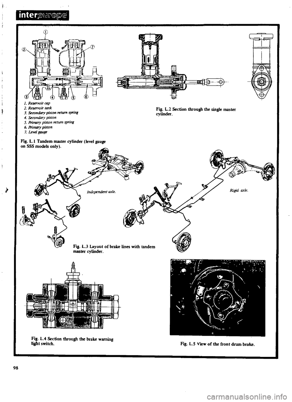
Fig
L
I
shows
a
cross
sectional
view
through
the
tandem
master
cylinder
and
Fig
L
2
a
cross
sectional
view
through
the
single
master
cylinder
The
removal
and
dismantling
procedures
are
similar
for
both
types
and
are
carried
out
in
the
following
manner
1
Remove
the
clevis
pin
and
separate
the
brake
pedal
from
the
master
cylinder
push
rod
2
Disconnect
the
brake
tubes
from
the
master
cylinder
3
Remove
the
master
cylinder
mounting
bolts
withdraw
the
shims
and
take
out
the
master
cylinder
assembly
MASfER
CYLINDER
Dismantling
and
Overhaul
Drain
the
brake
fluid
from
the
cylinder
and
remove
the
stopper
bolt
Remove
the
dust
cover
the
snap
ring
the
stopper
ring
and
the
pusbrod
assembly
Take
out
the
primary
piston
and
secondary
piston
assemblies
and
the
piston
spring
Remove
the
valve
cap
and
take
out
the
valve
assembly
Oean
all
the
components
with
brake
fluid
and
check
them
for
wear
or
damage
Make
sure
that
the
cylinder
bore
and
piston
are
not
damaged
or
unevenly
worn
The
clearance
between
cylinder
and
piston
must
not
exceed
0
15mm
0
006
in
REAR
DRUM
BRAKE
Adjusting
FRONT
DISC
BRAKE
Friction
pads
FRONT
DISC
BRAKE
Removal
and
Dismantling
FRONT
DISC
BRAKE
Assembly
and
Installation
HANDBRAKE
Removal
and
Installation
BLEEDING
THE
HYDRAULIC
SYSTEM
BRAKE
PEDAL
ADJUSTMENT
Check
the
return
springs
for
damage
or
loss
of
tension
Replace
any
part
which
is
in
an
unsatisfactory
condition
MASfER
CYLINDER
Assembly
and
Installation
Assembly
of
the
master
cylinder
is
a
reversal
of
the
dismantling
procedure
noting
the
following
points
Wet
the
cylinder
bore
and
piston
etc
with
brake
fluid
before
assembling
Care
must
be
taken
to
prevent
dust
and
foreign
matter
entering
the
cylinder
and
reservoir
Ensure
that
cups
and
soals
are
not
damaged
when
locating
them
After
the
master
cylinder
is
reinstalled
the
system
must
be
bled
and
the
pedal
height
adjusted
as
described
under
the
appropriate
headings
BRAKE
LINES
Replacing
The
layout
of
the
metal
brake
pipes
and
flexible
hoses
is
shown
in
Fig
L
3
The
brake
pipes
can
be
removed
by
taking
off
the
flare
nuts
at
both
ends
of
the
pipe
and
removing
the
clips
securing
the
pipe
to
the
body
Similarly
the
brake
hoses
can
be
removed
by
taking
off
the
flare
nuts
Thoroughly
clean
the
pipe
or
hose
after
removing
from
the
vehicle
and
check
for
collapsing
cracking
or
rusting
of
the
pipe
and
for
signs
of
expansion
and
weakening
of
the
hose
Any
pipe
or
hose
which
is
not
in
a
satisfactory
condition
must
be
renewed
Remove
any
dust
from
the
brake
clip
and
replace
the
clip
if
the
vinyl
coating
is
torn
Installation
is
a
reversal
of
the
removal
procedure
Make
sure
that
the
brake
pipes
cannot
vibrate
against
any
part
of
the
vehicle
and
the
brake
hoses
are
not
twisted
and
rubbing
against
the
tyres
or
suspension
units
If
the
brake
hose
is
disconnected
from
the
three
way
connector
on
the
rear
axle
housing
it
will
be
necessary
to
fit
a
new
copper
sealing
washer
Do
not
overtighten
the
installation
flare
nuts
the
correct
tightening
torques
are
as
follows
Three
way
connector
master
cylinder
and
brake
hoses
1
5
1
8
kgm
II
13Ib
ft
Fill
the
master
cylinder
with
recommended
fluid
and
bleed
the
system
as
described
under
the
appropriate
heading
Make
sure
that
fluid
is
not
leaking
from
any
part
of
the
system
by
fully
depressing
the
brake
pedal
for
several
seconds
Check
the
pipes
and
connections
and
replace
any
defective
part
99
Page 102 of 171
BRAKE
WARNING
UGHT
SWITCH
A
hydraulically
operated
warning
light
switch
is
located
in
the
engine
compartment
Fig
LA
The
front
and
rear
brake
systems
of
the
dual
circuit
are
connected
to
the
switch
which
provides
a
warning
via
the
warning
light
on
the
instrument
panel
when
a
pressure
difference
of
13
17
kg
sq
cm
185
242Ib
sq
in
occurs
between
the
front
and
rear
brake
systems
The
switch
cannot
be
repaired
and
must
be
renewed
if
faulty
FRONT
DRUM
BRAKE
Removal
1
Jack
up
the
front
of
the
vehicle
and
support
it
on
stands
2
Remove
the
brake
drum
and
the
hub
cap
and
hub
assembly
3
Disconnect
the
brake
pipe
at
the
bracket
on
the
front
suspension
strut
as
previously
described
in
the
section
FRONT
SUSPENSION
4
Unhook
the
two
return
springs
shown
in
Fig
L
5
and
remove
the
brake
shoes
5
Disconnect
the
bridge
pipe
3
in
Fig
L
6
and
remove
the
two
wheel
cylinders
6
Take
out
the
installation
bolts
and
withdraw
the
brake
backplate
from
the
spindle
FRONT
DRUM
BRAKE
Inspection
and
Overhaul
Examine
the
brake
drums
for
scoring
and
out
of
round
The
maximum
permissible
inner
diameter
of
the
drums
must
not
exceed
228
6mm
9
00
in
and
out
of
round
should
be
below
0
02mm
0
0008in
The
brake
shoe
linings
must
re
renewed
when
worn
down
to
a
thickness
of
1
5mm
0
06
in
or
below
Renew
the
linings
if
they
are
contaminated
in
any
way
or
incorrectly
seated
The
complete
set
of
linings
must
be
replaced
if
any
single
lining
is
unsatisfactory
O1eck
the
shoe
return
springs
and
if
they
have
become
weakened
replace
them
Withdraw
the
pistons
and
springs
from
the
wheel
cylinders
and
inspect
the
bore
of
the
cylinders
for
signs
of
wear
corrosion
or
damage
Renew
the
cylinder
and
the
piston
if
the
clearance
between
the
two
exceeds
O
15mm
0
006
in
Renew
the
rubber
boots
and
cups
FRONT
DRUM
BRAKE
Assembly
and
Installation
Assembly
and
installation
is
a
reversal
of
the
removal
and
dismantling
procedure
noting
the
fOllowing
points
Apply
a
thin
layer
of
special
grease
to
the
piston
cup
and
other
rubber
parts
when
assembling
the
wheel
cylinder
The
internal
components
of
the
cylinder
should
be
dipped
in
brake
fluid
and
assembled
whilst
still
wet
Install
the
wheel
cylinders
on
the
brake
backplate
and
smear
the
cylinder
backplate
and
cylinder
lever
fulcrum
with
grease
Fig
L
8
Tighten
the
backplate
mounting
bolts
to
a
torque
reading
of
2
7
3
7
kgm
19
5
26
71b
ft
Adjust
the
brake
shoes
and
bleed
the
hydraulic
system
as
described
under
the
appropriate
headings
REAR
DRUM
BRAKE
REMOVAL
Fig
L
IO
Jack
up
the
vehicle
at
the
rear
and
support
it
on
stands
Remove
the
road
wheel
2
Release
the
handbrake
remove
the
clevis
pin
3
from
the
rear
wheel
cylinder
lever
4
see
Fig
L
9
Disconnect
the
handbrake
cable
2
and
remove
the
return
spring
I
3
Remove
the
brake
drum
Remove
the
shoe
retainers
the
return
springs
and
brake
shoes
Fig
L
II
4
Disconnect
the
fluid
line
from
the
wheel
cylinders
and
plug
the
opened
end
to
prevent
to
loss
of
fluid
5
Remove
the
dust
cover
adjusting
shims
and
plates
then
remove
the
wheel
cylinder
from
the
backplate
6
The
brake
backplate
and
axle
shaft
assembly
can
be
with
drawn
if
necessary
by
taking
out
the
four
flange
bolts
and
removing
the
assembly
as
described
in
the
section
REAR
AXLE
AND
REAR
SUSPENSION
REAR
DRUM
BRAKE
Inspection
and
Overhaul
The
inspection
and
overhaul
procedures
fpr
the
rear
drum
brakes
are
similar
to
those
previously
described
for
the
front
drum
brakes
Tighten
the
brake
backplate
mounting
bolts
to
a
torque
reading
of
3
9
5
3
kgm
28
38Ib
ft
FRONT
DRUM
BRAKE
Adjusting
Jack
up
the
vehicle
and
pump
the
brake
pedal
several
times
With
the
brake
drum
installed
turn
one
of
the
adjusting
cams
clockwise
until
the
brake
shoe
is
in
contact
with
the
drum
This
operation
is
carried
out
from
the
rear
of
the
backplate
When
the
brake
shoe
contacts
the
drum
turn
the
cam
in
the
opposite
direction
until
the
shoe
is
just
clear
and
the
brake
drum
can
be
rotated
freely
by
hand
Repeat
the
operation
on
the
other
adjusting
cam
and
then
depress
the
brake
pedal
to
make
sure
that
the
brakes
are
working
correctly
The
adjusters
must
be
released
slightly
if
the
brake
drum
binds
when
turned
by
hand
Fig
L
12
shows
the
adjusting
cams
REAR
DRUM
BRAKE
Adjusting
Jack
up
the
vehicle
at
the
rear
and
pump
the
brake
pedal
several
times
Turn
the
brake
shoe
adjuster
Fig
L
13
until
the
101
Page 104 of 171
brake
shoe
is
in
contact
with
the
drum
The
adjuster
must
be
turned
from
the
rear
of
the
backplate
and
the
drum
turned
by
hand
When
the
shoe
contacts
the
drum
turn
the
adjuster
in
the
opposite
direction
until
the
shoe
is
just
clear
and
the
drum
can
be
rotated
freely
by
hand
Depress
the
brake
pedal
and
make
sure
that
the
brakes
operate
correctly
The
adjusters
must
be
released
slightly
if
the
brake
shoe
binds
FRONT
DISC
BRAKE
Friction
pads
Fig
L
14
The
disc
brakes
are
self
adjusting
but
the
friction
pads
should
be
checked
for
wear
every
5
000
km
3
000
miles
and
replaced
if
the
thickness
of
the
friction
lining
on
any
pad
is
less
than
1
0mm
0
004
in
In
effect
this
means
that
renewal
is
necessary
when
the
total
thickness
of
pad
and
lining
is
less
than
8
4mm
0
24
in
To
replace
the
friction
pads
proceed
as
follows
Siphon
out
some
of
the
fluid
in
the
master
cylinder
reservoir
Jack
up
the
front
of
the
vehicle
and
remove
the
road
wheel
Remove
the
anti
rattle
clip
from
the
calliper
plate
Fig
L
lS
Unhook
the
hanger
spring
and
withdraw
the
brake
pads
and
shims
Fig
L
17
It
should
be
noted
that
the
friction
pads
must
be
replaced
as
a
set
and
renewed
at
both
sides
of
the
vehicle
otherwise
the
braking
action
will
be
uneven
Oean
the
calliper
and
pad
at
their
installation
positions
Press
the
pistons
into
the
calliper
bores
so
that
the
new
friction
Pads
can
be
installed
The
pistons
can
be
installed
by
applying
light
pressure
as
shown
in
Fig
L
16
but
care
must
be
taken
to
avoid
pushing
them
too
far
or
the
groove
of
the
piston
will
damage
the
seal
If
the
pistons
are
pushed
down
excessively
it
will
be
necessary
to
dismantle
the
calliper
as
described
under
the
appropriate
heading
Assemble
the
anti
squeal
shims
to
the
friction
pads
with
the
arrow
mark
on
the
shims
pointing
in
the
direction
of
forward
disc
rotation
Refit
the
pads
and
retaining
pins
and
assemble
the
coil
spring
to
the
retaining
pin
furthest
away
from
the
air
bleed
screw
After
installing
the
new
pads
and
shims
depress
the
brake
pedal
several
times
to
reposition
the
pistons
in
the
calliper
O1eck
the
fluid
level
in
the
master
cylinder
reservoir
and
refill
to
the
correct
level
FRONT
DISC
BRAKE
Removal
and
Dismantling
1
Jack
up
the
front
of
the
vehicle
remove
the
road
wheel
and
take
out
the
friction
pads
2
Disconnect
the
brake
hose
from
the
brake
tube
and
plug
the
opened
end
to
prevent
the
loss
of
fluid
3
Remove
the
bolts
securing
the
brake
calliper
to
the
knuckle
flange
and
remove
the
calliper
assembly
Fig
L
IS
4
Remove
the
hub
nut
and
withdraw
the
hub
and
disc
To
dismantle
the
calliper
remove
the
anti
rattle
clip
and
withdraw
the
brake
pads
Remove
the
tension
springs
and
pull
the
cylinder
out
of
the
calliper
Blow
out
the
piston
with
com
pressed
air
applied
at
the
brake
hose
connection
Oean
the
components
in
brake
fluid
and
examine
them
for
signs
of
wear
or
damage
The
cylinder
walls
can
be
carefully
polished
with
fine
emery
cloth
if
they
are
rusted
or
contaminated
If
the
parts
are
excessively
corroded
they
should
be
renewed
Replace
the
pistons
if
they
are
unevenly
worn
damaged
or
rusted
The
sliding
surface
of
the
piston
is
plated
and
no
attempt
should
be
made
to
use
emery
cloth
or
similar
abrasives
for
cleaning
purposes
Check
the
thickness
of
the
friction
pads
as
previously
described
and
replace
them
if
necessary
Renew
the
piston
seals
and
the
dust
covers
O1eck
the
brake
disc
for
scoring
and
out
of
round
The
standard
disc
thickness
is
10
Omm
0
0394
in
and
must
not
be
reground
below
8
4mm
0
3307
in
Check
the
disc
run
out
with
a
dial
gauge
as
shown
in
Fig
L
19
Position
the
gauge
near
the
outer
diameter
and
check
that
the
run
out
does
not
exceed
0
06mm
0
0024
in
FRONT
BRAKE
DISC
Assembly
and
Installation
Rinse
the
cylinder
bore
with
brake
fluid
and
fit
the
piston
seal
into
the
cylinder
groove
Fig
L
20
Fit
the
wiper
seal
and
lightly
grease
the
bore
of
the
cylinder
Clean
the
brake
disc
and
fit
it
to
the
hub
Install
the
hub
to
the
knuckle
spindle
Carefully
insert
the
piston
into
the
cylinder
until
the
face
of
the
piston
is
almost
flush
with
the
wiper
seal
retainer
The
relieved
part
of
the
piston
should
face
the
piston
pin
Fit
the
cylinder
to
the
calliper
plate
and
secure
in
position
with
the
two
torsion
springs
Assemble
the
hold
down
pin
the
spring
washer
and
the
nut
to
the
support
bracket
Secure
the
nut
with
a
cotter
pin
Assemble
the
calliper
to
the
mounting
bracket
using
the
pivot
pin
washer
spring
washer
and
nut
Tighten
the
nut
and
secure
with
a
cotter
pin
Hook
the
hold
down
bracket
to
the
top
of
the
mounting
bracket
and
turn
the
calliper
plate
to
make
sure
that
it
can
slide
smoothly
Fit
the
calliper
assembly
to
the
knuckle
flange
Fit
a
shim
to
the
inner
pad
and
insert
the
pad
Draw
the
calliper
towards
the
chassis
and
insert
the
lower
cuts
on
the
pad
into
the
mounting
bracket
and
push
the
pad
in
until
it
contacts
the
piston
Move
the
calliper
away
from
the
chassis
and
insert
the
upper
cuts
Centre
the
indentation
of
the
outer
pad
in
the
calliper
plate
Fit
the
anti
rattle
clip
Fig
L
14
103
Page 108 of 171
BRAKE
PEDAL
ADJUSTMENT
The
brake
pedal
height
and
free
play
can
be
adjusted
in
the
following
manner
1400
and
1600
CC
models
Adjust
the
length
of
the
master
cylinder
push
rod
until
the
height
of
the
pedal
pad
is
187
mm
7
36
in
for
manual
gear
boxes
and
202
mm
7
95in
for
automatic
transmission
vehicles
without
brake
light
switch
Fig
L
31
Retighten
the
locknut
Screw
in
the
brake
light
switch
until
the
screwed
part
of
the
switch
is
against
the
front
of
the
stopper
bracket
then
tighten
the
locknut
Screw
in
the
stopper
bolt
until
the
moveable
part
of
the
switch
is
completely
pushed
in
by
the
pedal
and
tighten
the
locknut
in
this
position
Make
sure
that
the
lamp
is
00
when
the
pedal
is
pushed
down
by
1
5mm
0
06
in
1800cc
models
Adjust
the
bolt
of
the
brake
lamp
switch
until
its
end
face
is
flush
with
the
locknut
then
tighten
the
locknut
securely
See
Fig
L
32
Adjust
the
pedal
stopper
until
the
pedal
pad
is
positioned
at
a
height
of
185
mrn
7
28
in
from
the
floor
then
tighten
the
stopper
with
the
locknut
Adjust
the
length
of
the
master
cylinder
push
rod
until
a
pedal
free
play
of
I
5mm
0
04
D
2in
is
obtained
then
retighten
the
locknut
Depress
the
brake
pedal
several
times
to
make
sure
that
a
full
travel
of
145mm
5
7
in
is
available
and
that
the
pedal
moves
freely
and
without
noise
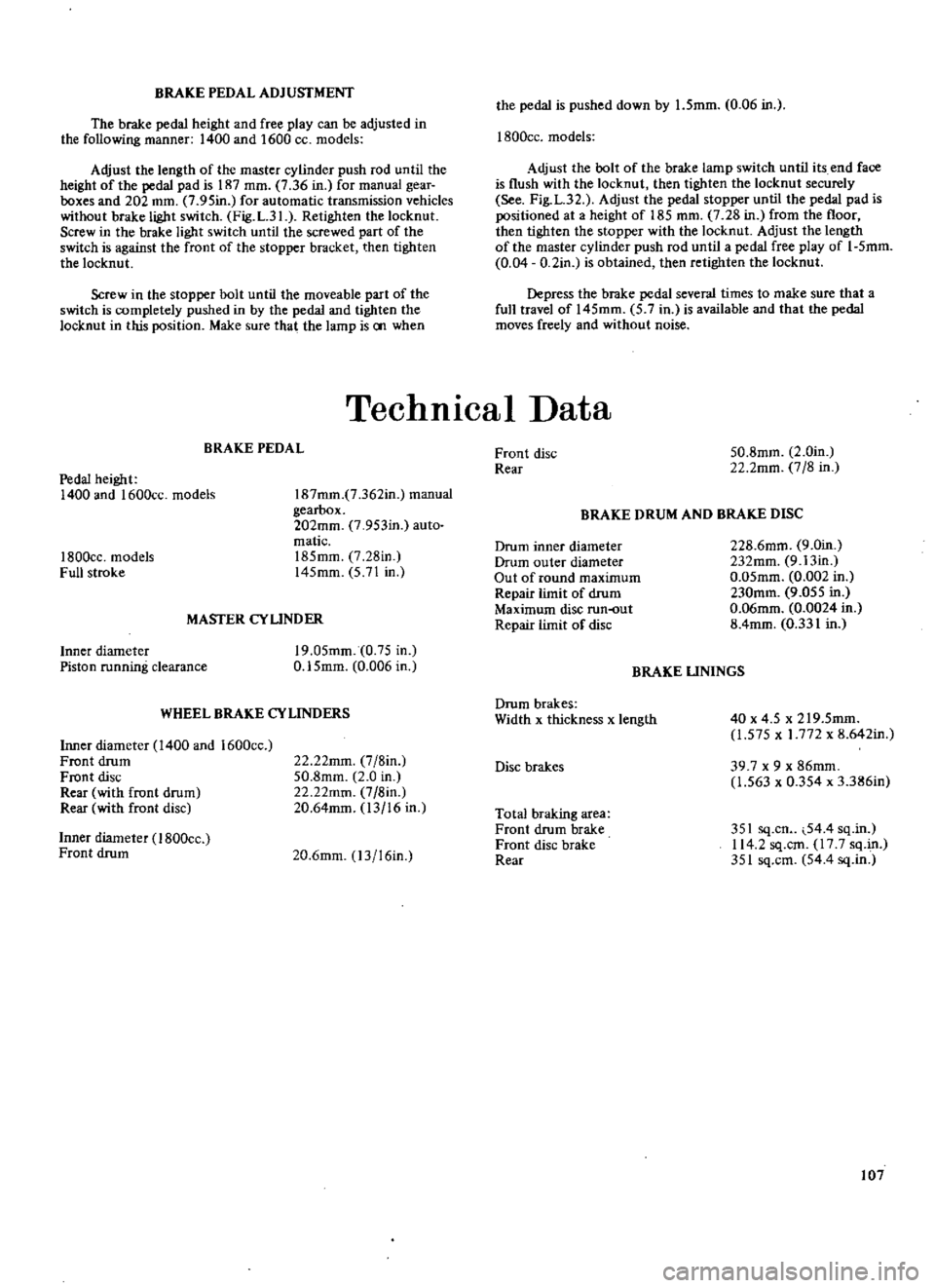
Technical
Data
BRAKE
PEDAL
Pedal
height
1400
and
1600cc
models
I
87mm
7
362in
manual
gearbox
202mm
7
953in
auto
matic
185mm
7
28in
145mm
5
71
in
1800cc
models
Full
stroke
MASTER
CYUNDER
Inner
diameter
Piston
running
clearance
19
05mm
0
75
in
0
15mm
0
006
in
WHEEL
BRAKE
CYLINDERS
Inner
diameter
1400
and
1600cc
Front
drum
Front
disc
Rear
with
front
drum
Rear
with
front
disc
22
22mm
7
8in
50
8mm
2
0
in
22
22mm
7
8in
20
64mm
13
16
in
Inner
diameter
I
BOOcc
Front
drum
20
6mm
13
16in
Front
disc
Rear
50
8mm
2
0in
22
2mm
7
8
in
BRAKE
DRUM
AND
BRAKE
DISC
Drum
inner
diameter
Drum
outer
diameter
Out
of
round
maximum
Repair
limit
of
drum
Maximum
disc
run
out
Repair
limit
of
disc
228
6mm
9
0in
232mm
9
13in
0
05mm
0
002
in
230mm
9
055
in
0
06mm
0
0024
in
8
4mm
0
331
in
BRAKE
UNINGS
Drum
brakes
Width
x
thickness
x
length
40
x
4
5
x
219
5mm
1
575
x
1
772
x
8
642in
Disc
brakes
39
7
x
9
x
86mm
1
563
x
0
354
x
3
386in
Total
braking
area
Front
drum
brake
Front
disc
brake
Rear
351
sq
cn
54
4
sq
in
114
2
sq
cm
17
7
sq
in
351
sq
cm
54
4
sq
in
107
Page 156 of 171
Remove
the
road
wheel
and
disconnect
the
brake
hose
at
the
connector
as
shown
in
Fig
C
4
of
this
section
Remove
the
brake
calliper
assembly
and
hub
cap
Withdraw
the
cotter
pin
and
remove
the
wheel
bearing
locknut
Remove
the
wheel
bearing
washer
and
take
off
the
hub
and
brake
disc
Fig
C
5
Remove
the
bearing
collar
take
out
the
outer
bearing
cage
and
prise
out
the
hub
grease
seal
Remove
the
inner
bearing
cage
and
drive
out
the
outer
races
of
the
inner
and
outer
bearings
using
the
special
drift
ST49120000
if
avail
able
Separate
the
brake
disc
from
the
hub
by
taking
out
the
retaining
bolts
as
shown
in
Fig
C
6
Installation
is
a
reversal
of
the
removal
procedure
Adjust
the
wheel
bearings
as
previously
described
taking
care
to
tighten
the
wheel
bearing
locknut
to
the
specified
torque
read
ing
of
3
0
to
3
5
kgm
21
7
to
25
3lb
ft
Turn
the
hub
several
times
to
settle
the
bearing
then
retighten
the
nut
to
the
same
figure
Slacken
the
locknut
by
a
quarter
turn
900
and
insert
the
cotter
pin
when
the
hole
in
the
spindle
is
aligned
with
the
hole
in
the
nut
Check
that
the
force
required
to
turn
the
hub
is
less
than
7
0
kg
cm
97
2
in
oz
STABILIZER
Removal
and
Installation
Remove
the
splash
board
and
take
off
the
bolts
I
in
Fig
C
7
which
attach
the
stabilizer
at
the
transverse
link
sides
Remove
the
bolts
attaching
the
stabilizer
bracket
2
to
the
frame
then
withdraw
the
stabilizer
Check
the
bar
and
rubber
components
for
signs
of
deforma
tion
or
damage
and
renew
as
necessary
Installation
is
a
reversal
of
the
removal
procedures
Tighten
the
fixing
bolts
to
a
torque
reading
of
1
2
to
I
7
kgm
8
7
to
12
3
lb
ft
at
the
transverse
link
side
and
1
9
to
2
5
kgm
13
7
to
18
llb
ft
at
the
frame
bracket
SPRING
AND
STRUT
ASSEMBLY
The
spring
and
strut
assembly
can
be
serviced
by
following
the
instructions
previously
given
for
the
assemblies
on
vehicles
fitted
with
the
L14
L16
and
Ll8engines
When
reassembling
make
sure
that
the
parts
shown
in
Fig
C
8
are
thomughly
greased
Installation
of
the
assembly
will
be
accomplished
more
easily
if
the
dust
cover
on
the
bonnet
ledge
is
removed
Tighten
the
nuts
and
bolts
to
a
torque
figures
given
in
TIGHTENING
TORQUES
TRANSVERSE
LINK
AND
LOWER
BALL
JOINT
The
transverse
link
and
lower
ball
joint
can
be
removed
in
a
similar
manner
to
the
parts
on
vehicles
fitted
with
L
14
L
16
and
L
18
engines
Renew
the
link
if
cracked
or
damaged
in
any
way
Check
the
measurement
A
in
Fig
C
9
The
measurement
between
front
and
rear
transverse
link
bushes
should
be
less
than
1
0
mm
0
039
in
Replace
the
bushes
if
necessary
The
lower
ball
joint
should
be
replaced
if
the
axial
play
of
the
joint
exceeds
0
03
to
0
6
mm
0
0012
to
0
0136
in
A
grease
nipple
must
be
installed
in
place
of
the
ball
joint
plug
so
that
the
joint
can
be
lubricated
with
multi
purpose
grease
as
previously
described
SUSPENSION
MEMBER
Removing
and
Installing
Jack
up
the
vehicle
and
support
it
on
stands
2
Remove
the
splash
board
Refer
to
Fig
C
I
0
and
detach
the
compression
rod
I
the
stabilizer
2
from
the
trans
verse
link
3
Detach
the
steering
linkage
from
the
suspen
sion
crossmember
4
3
Take
out
the
nuts
attaching
the
transverse
links
and
remove
the
links
at
both
sides
of
the
vehicle
4
Support
the
engine
with
a
hoist
as
shown
in
Fig
C
II
taking
care
not
to
damage
the
throttle
and
remote
control
linkages
and
then
remove
the
engine
mounting
bolts
at
both
sides
5
Remove
the
bolts
shown
arrowed
in
Fig
C
12
and
lift
the
suspension
member
away
Renew
the
suspension
member
if
it
is
cracked
or
deformed
in
any
way
Installation
is
a
reversal
of
the
removal
procedure
FRONT
WHEEL
ALIGNMENT
As
previously
stated
the
castor
and
camber
angles
are
preset
and
cannot
be
adjusted
A
thorough
check
should
be
made
of
the
steering
and
suspension
system
and
all
defective
parts
renewed
if
the
angles
are
incorrect
See
Technical
Data
The
front
wheels
should
toe
in
12
to
15
mm
0
4
7
to
0
59
in
Adjustment
can
be
carried
out
by
slackening
the
locknuts
1
in
Fig
C
13
and
then
turning
the
tie
rods
by
an
equal
amount
until
the
correct
toe
in
is
achieved
A
toe
in
gauge
will
of
course
be
required
for
this
operation
STEERING
WHEEL
AND
COLUMN
Removal
Disconnect
the
horn
wire
and
remove
the
horn
bar
Remove
the
steering
wheel
nut
and
pull
off
the
steering
wheel
2
Remove
the
turn
signal
and
lighting
switch
assembly
followed
by
the
steering
column
shell
covers
3
Remove
the
bolts
from
the
rubber
coupling
to
disconnect
the
lower
joint
See
Figs
C
14
and
C
I
5
if
the
car
is
fitted
with
right
hand
drive
The
lower
joint
upper
bolt
should
be
removed
to
disconnect
the
joint
if
the
car
is
fitted
with
left
hand
drive
4
Remove
the
cotter
pin
from
the
trunnion
and
disconnect
the
gearchange
rod
and
selector
rod
5
Remove
the
steering
column
upper
clamp
and
take
out
the
bolts
securing
the
lower
plate
STEERING
COLUMN
Dismantling
and
Assembling
Remove
the
C
washer
socket
screw
and
upper
bracket
bolt
Remove
the
lower
bracket
bolts
and
detach
the
remote
control
linkage
from
the
column
assembly
Remove
the
snap
ring
at
the
top
of
the
column
and
extract
the
column
shaft
from
the
jacket
Disconnect
the
rubber
coupling
from
the
lower
joint
then
remove
the
snap
ring
and
dismantle
the
lower
joint
S25
Page 162 of 171
BrakIng
System
Description
Front
disc
brake
Friction
pads
Front
disc
brake
Removal
and
Installation
Rear
drum
brake
Removal
and
Installation
Master
Vac
Servo
Unit
Handbrake
cables
Removing
Handbrake
Adjusting
Brake
pedal
Adjusting
Rear
drum
brake
Adjusting
Bleeding
the
hydraulic
system
DESCRIPTION
The
vehicle
is
fitted
with
disc
brakes
for
the
front
wheels
and
leading
trailing
shoe
type
drum
brakes
for
the
rear
wheels
A
conventional
single
master
cylinder
is
fitted
to
the
Standard
and
DeLuxe
models
See
Fig
D
I
for
details
The
DeLuxe
models
are
however
additio
ally
equipped
with
a
Master
Vae
servo
unit
which
provides
a
much
higher
braking
performance
with
minimum
force
required
on
the
brake
pedal
A
tandem
master
cylinder
and
Master
Vac
servo
unit
are
fitted
as
standard
equipment
to
the
Datsun
CL30UA
and
CL3
OUT
models
Fig
D
2
gives
an
exploded
view
of
this
type
of
master
cylinder
The
handbrake
is
of
the
mechanical
type
with
the
handle
linked
to
the
rear
shoe
operating
lever
through
a
system
of
rods
and
wires
See
Fig
D
3
As
on
previous
models
a
brake
pressure
differential
warn
ing
light
switch
is
incorporated
with
dual
brake
circuits
The
front
and
rear
brake
systems
are
connected
to
the
switch
which
provides
a
warning
via
a
warning
light
on
the
instnllnent
panel
when
a
pressure
difference
of
13
to
17
kg
sq
cm
IB5
to
242
lb
sq
in
occurs
between
the
front
and
rear
systems
Brake
piping
layouts
of
the
single
and
tandem
master
cylinder
systems
are
shown
in
Figs
D
4
and
0
5
FRONT
DISC
BRAKE
Friction
pads
The
disc
brakes
are
self
adjusting
but
the
friction
pads
should
be
checked
for
wear
after
the
fIrst
6
000
un
4
000
miles
and
then
every
5
000
km
3
000
miles
The
pads
must
be
replaced
if
the
friction
lining
on
any
pad
has
worn
to
less
than
1
0
mm
0
04
in
The
thickness
of
the
pads
can
easily
be
checked
after
remov
ing
the
anti
rattle
clip
from
the
calliper
plate
Full
servicing
procedures
are
given
in
the
section
BRAKING
SYSTEM
for
vehicles
fitted
with
Ll4
Ll6
and
Ll8
engines
FRONT
DISC
BRAKE
Removal
and
Installation
Refer
to
the
section
BRAKING
SYSTEM
for
the
Ll4
L16
and
LIB
engines
for
full
details
of
the
removal
and
installation
procedures
Check
the
thickness
of
the
friction
pads
as
previously
described
and
replace
them
if
necessary
Check
the
brake
disc
for
scoring
and
out
of
round
The
standard
diSc
thickness
is
10
0
mm
0
394
in
and
must
not
be
reground
below
8
40
mm
0
331
in
The
run
out
of
the
disc
should
be
less
than
0
06
mm
0
0024
in
and
can
be
checked
with
a
dial
gauge
positioned
near
the
outer
diameter
of
the
disc
as
previously
described
REAR
DRUM
BRAKE
Removal
and
Installation
The
rear
drum
brakes
See
Fig
D
6
can
be
removed
and
inspected
as
described
in
the
section
BRAKING
SYSTEM
for
vehicles
fItted
with
L14
L16
LIB
engines
Examine
the
brake
drums
for
scoring
and
out
of
round
The
maximum
inner
diameter
of
the
drum
must
not
exceed
229
6
mm
9
040
in
after
reconditioning
Out
of
round
should
be
below
0
05
mm
0
002
in
Renew
the
brake
shoe
linings
if
they
are
contaminated
or
incorrectly
seated
or
if
the
thickness
of
the
lining
has
been
reduced
to
1
5
mm
0
06
in
or
less
Oil
or
grease
can
be
re
moved
from
the
linings
by
cleaning
thoroughly
with
carbon
tetrachloride
or
petrol
Check
the
shoe
return
springs
and
replace
them
if
they
have
become
weakened
Check
the
bores
of
the
wheel
cylinders
for
signs
of
wear
damage
or
corrosion
Renew
the
cylinders
and
pistons
if
the
clearance
between
the
two
parts
exceeds
to
0
15
mm
0
006
in
Renew
the
c
ps
when
overhauling
the
wheel
cylinders
MASTER
V
AC
SERVO
UNIT
Removing
and
Dismantling
The
servo
unit
should
be
removed
and
overhauled
at
yearly
intervals
A
Master
Vac
repair
kit
is
available
and
all
parts
marked
in
Fig
D
7
should
be
renewed
after
dismantling
the
unit
These
items
are
all
supplied
as
part
of
the
repair
kit
The
unit
can
be
removed
as
follows
Remove
the
clevis
pin
from
the
push
rod
and
detach
the
Master
V
ac
unit
from
the
brake
pedal
2
Disconnect
the
brake
tube
from
the
master
cylinder
and
the
vacuum
hooe
from
the
Master
Vac
3
Take
off
the
retaining
nuts
and
remove
the
Master
Vac
and
spacer
then
separate
the
master
cylinder
from
the
Master
Vac
Mark
the
front
cylinder
shell
and
the
rear
shell
and
stud
assembly
before
dismantling
the
unit
then
proceed
as
follows
S31