drain bolt DATSUN 610 1969 User Guide
[x] Cancel search | Manufacturer: DATSUN, Model Year: 1969, Model line: 610, Model: DATSUN 610 1969Pages: 171, PDF Size: 10.63 MB
Page 82 of 171
the
steel
balls
and
the
sleeve
yoke
for
damage
or
wear
Renew
the
boots
and
the
sleeve
yoke
plug
0
ring
if
necessary
Renew
the
universal
joint
jf
faulty
Check
the
play
in
the
drive
shaft
using
a
dial
gauge
as
shown
in
Fig
H
18
The
measurement
taken
with
the
dri
le
shaft
fully
compressed
should
not
exceed
O
lmm
0
004
in
Renew
the
drive
shaft
as
embly
if
the
specified
value
is
not
obtained
Oean
the
old
grease
from
the
sleeve
yoke
and
the
drive
shaft
ball
grooves
and
lubricate
with
oil
Asse
bly
of
the
drive
shaft
is
a
reversal
of
the
dismantling
procedure
noting
the
following
points
Align
the
yokes
and
make
sure
that
the
steel
balls
and
spacers
are
fitted
in
the
correct
order
Select
a
snap
ring
which
will
adjust
the
axial
play
of
the
universaIjoints
to
within
0
02mm
0
0008
in
Snap
rings
are
available
in
four
thicknesses
of
1
49
1
52
1
55
and
1
58
mm
0
0587
0
0598
0
0610
0
0622
in
Apply
a
generous
quantity
of
multi
purpose
grease
to
the
ball
groove
and
the
area
shown
in
Fig
H
19
REAR
AXLE
Removal
See
Fig
H
2
Estate
car
and
Van
Jack
up
the
vehicle
at
the
rear
and
support
it
on
stands
Remove
the
road
wheels
and
brake
drums
I
3
Disconnect
the
brake
hose
from
the
brake
pipe
Plug
the
end
of
the
hose
to
prevent
the
ingress
of
foreign
matter
4
Disconnect
the
handbrake
rear
cable
from
the
balance
lever
assembly
5
Disconnect
the
propeller
shaft
from
the
differential
flange
Release
the
lower
shock
absorber
self
locking
nuts
and
slide
the
mounting
eyes
of
the
shock
absorber
from
the
rear
spring
seat
pivot
6
Support
the
rear
axle
with
ajack
loosen
the
U
bolts
and
remove
the
nuts
from
the
rear
spring
shackles
Withdraw
the
shackles
from
the
spring
eyes
7
Remove
the
V
bolt
lock
nuts
completely
and
lower
the
jack
to
withdraw
the
rear
axle
assembly
REAR
AXLE
Dismailtling
and
Inspection
Disconnect
the
brake
pipes
from
the
wheel
cylinders
and
remove
the
brake
pipe
and
three
way
connector
Remove
the
cross
rod
clamp
and
the
balance
lever
from
the
rear
axle
case
Remove
both
cross
rod
ends
from
the
wheel
cylinder
lever
assembly
Unscrew
the
oil
drain
plug
and
drain
the
oil
from
the
axle
case
into
a
clean
container
The
oil
may
be
re
used
if
it
is
in
good
condition
Remove
the
nuts
securing
the
brake
backplate
to
the
axle
case
and
draw
out
the
axle
shaft
assembly
with
the
backpl
te
and
grease
catcher
A
sliding
hammer
ST
36230000
should
be
used
for
this
operation
as
shown
in
Fig
H
2Q
The
bearing
collar
can
be
removed
with
a
press
or
by
cutting
with
a
cold
chisel
and
the
bearing
withdrawn
with
the
puller
ST
3712001
as
shown
in
Fig
H
2t
Remove
the
brake
backplate
and
withdraw
the
gear
carrier
from
the
axle
case
Check
the
axle
shafts
for
straightness
wear
and
cracks
00
NOT
attempt
to
straighten
a
bent
shaft
by
heating
Check
the
oil
seal
lips
for
signs
of
damage
or
distortion
Make
sure
that
the
bearing
is
not
worn
or
damaged
REAR
AXLE
Assembly
and
Installation
Assembly
is
a
reversal
of
the
removal
procedure
noting
the
following
points
Thoroughly
clean
all
parts
and
fit
a
new
gasket
between
the
axle
case
and
gear
carrier
Tighten
the
nuts
in
a
diagonal
pattern
and
to
the
specified
torque
readings
Fit
the
grease
catcher
bearing
spacer
bearing
and
new
bearing
collar
onto
the
axle
shaft
A
load
of
4
5
tons
will
be
required
to
press
the
bearing
onto
the
shaft
Insert
the
wheel
bearing
with
the
seal
side
facing
the
wheel
and
ensure
that
the
oil
seal
lips
are
coated
with
wheel
bearing
grease
prior
to
fitting
Check
and
adjust
the
axial
play
between
the
wheel
bearing
and
the
axle
housing
using
a
dial
gauge
as
shown
in
Fig
H
22
The
axial
play
should
be
adjusted
to
within
0
3
0
5mm
0
0118
0
0197
in
on
the
1400
and
1600cc
models
and
to
within
O
lmm
0
0039
in
on
the
1800cc
models
Fill
the
rear
axle
with
the
specified
amount
of
oil
and
bleed
and
adjust
the
brake
system
as
described
in
the
appropriate
section
REAR
SPRING
Removal
and
Inspection
Estate
cars
aud
Vans
The
rear
springs
can
be
removed
in
the
following
manner
Jack
up
the
vehicle
at
the
rear
until
the
wheels
are
clear
of
the
ground
and
place
stands
under
the
rear
frame
Disconnect
the
shock
absorber
from
the
spring
seat
Fig
H
21a
and
support
the
rear
axle
housing
with
ajack
3
Take
off
the
locknuts
and
remove
the
U
bolts
shown
arrowed
in
Fig
H
2t
the
spring
seat
location
plates
and
seat
pads
4
Remove
the
nuts
securing
the
front
bracket
to
the
body
remove
the
bracket
from
the
spring
eye
and
car
body
and
withdraw
the
rear
spring
5
Remove
the
upper
and
lower
rear
shackle
nuts
Fig
H
23
and
remove
the
rear
spring
from
the
vehicle
Clean
the
spring
leaves
thoroughly
and
examine
them
for
fractures
or
cracks
Renew
the
assembly
if
necessary
Check
the
front
pin
shackle
U
boIts
and
spring
seat
for
signs
of
wear
cracks
and
damaged
threads
Renew
the
components
as
required
REAR
SPRING
Installation
Installation
of
the
rear
spring
is
a
reversal
of
the
removal
procedure
noting
the
following
points
The
front
bracket
pin
front
bracket
bushing
shackle
pin
and
shackle
bushing
should
be
coated
with
a
soapy
solution
prior
to
assembly
Tighten
the
front
pin
securing
nut
and
the
shock
absorber
lower
securing
nut
with
the
vehicle
weight
resting
on
the
rear
wheels
Ensure
that
the
flange
of
the
shackle
bushing
is
clamped
evenly
on
both
sides
The
tightening
torque
values
can
be
found
on
the
page
entitled
TIGHTENING
TORQUES
81
Page 88 of 171
the
castle
nut
and
detach
the
tie
rod
from
the
knuckle
arm
5
Remove
the
tension
rod
securing
nuts
Fig
J
7
remove
the
bolts
and
withdraw
the
tension
rod
Withdraw
the
nut
shown
arrowed
in
FigJ
8
and
remove
the
stabilizer
6
Support
the
engine
with
suitable
lifting
tackle
so
that
the
engine
mounting
bolts
can
be
removed
and
the
suspension
crossmember
detached
from
the
engine
FigJ
9
7
Place
ajack
under
the
crossmember
Remove
the
bolts
indicated
in
Fig
J
IO
and
separate
the
crossmember
from
the
body
8
Remove
the
strut
assembly
upper
attachment
self
locking
nuts
at
both
sides
Fig
J
ll
and
lower
the
front
suspension
assembly
to
remove
it
from
the
vehicle
FRONT
AXLE
AND
SUSPENSION
ASSEMBLY
Installation
Installation
is
a
reversal
of
the
removal
procedure
noting
the
following
points
Make
sure
that
all
rubber
parts
are
free
from
wear
and
deterioration
Any
part
of
the
suspension
assembly
which
has
been
damaged
or
distorted
must
be
replaced
The
front
wheel
alignment
should
be
checked
after
completing
the
installation
a
brief
description
is
given
at
the
end
of
this
section
Camber
and
castor
angles
are
preset
and
cannot
be
adjusted
SPRING
AND
STRUf
ASSEMBLY
Removal
and
Installation
The
strut
assembly
consists
of
the
outer
casing
piston
rod
piston
rod
guide
and
cylinder
etc
An
exploded
view
of
the
components
is
given
in
Fig
J
12
The
inner
components
must
be
replaced
as
a
complete
assembly
Replacement
and
overhaul
procedures
for
the
inner
components
together
with
the
removal
of
the
front
springs
should
only
be
carried
out
by
a
specialist
Datsun
workshop
The
strut
assembly
can
be
removed
prior
to
dismantling
by
following
the
procedures
outlined
below
Jack
up
the
front
of
the
vehicle
and
support
it
on
stands
2
Disconnect
the
brake
hose
from
the
strut
assembly
bracket
as
previously
described
under
the
heading
FRONT
AXLE
and
SUSPENSION
ASSEMBLY
Removal
3
Remove
the
stabilizer
bar
and
tension
rod
from
the
trans
verse
links
Loosen
and
remove
the
knuckle
arm
fixing
bolts
Fig
J
9
And
separate
the
strut
assembly
from
the
ball
joints
4
Remove
the
strut
assembly
upper
attachment
self
locking
nuts
Fig
J
11
and
withdraw
the
strut
assembly
from
the
body
Fig
J
13
Installation
is
a
reversal
of
the
removal
procedure
Ensure
that
the
bolts
are
tightened
to
the
specified
torque
readings
given
under
TIGHTENING
TORQUES
SPRING
AND
STRUT
ASSEMBLY
Dismantling
and
Assembly
Care
must
be
taken
when
dismantling
the
assembly
to
ensure
that
aU
parts
are
maintained
in
a
clean
condition
Clamp
the
suspension
strut
assembly
in
a
vice
and
fit
the
special
attachment
ST
2770000
I
to
the
lower
end
of
the
strut
Prise
off
the
dust
cover
snap
ring
Use
the
coil
spring
compressor
ST
35650001
to
slightly
compress
the
spring
Remove
the
self
locking
nut
and
take
off
the
mounting
insulator
thrust
bearing
spring
seat
and
bump
rubber
Slacken
the
spring
compressor
and
remove
the
spring
Push
down
the
shock
absorber
piston
until
it
bottoms
and
remove
the
gland
packing
with
the
special
tool
ST
35500001
Fig
J
14
Remove
the
O
ring
from
the
piston
rod
guide
and
lift
out
the
piston
rod
and
cy
linder
assembly
00
NOT
separate
the
piston
and
cylinder
which
are
serviced
as
a
complete
assembly
Drain
all
fluid
from
the
suspension
unit
and
shock
absorber
assembly
Wash
all
parts
thoroughly
not
rubber
parts
in
petrol
or
a
suitable
solvent
The
gland
packing
and
0
ring
must
be
renewed
at
each
overhaul
Always
refill
with
the
correct
grade
of
fresh
oil
in
accordance
with
the
information
in
the
table
below
ATSUGI
KAYABA
Part
No
54302
UO
100
UOl10
325
cc
332
cc
54302
3
U0500
1
54302
N
1200
325
cc
300
cc
The
oil
quantity
is
extremely
critical
as
it
will
affect
the
damping
power
of
the
shock
absorber
To
assemble
fit
the
rubber
O
ring
on
the
top
of
the
piston
rod
and
refit
the
gland
packing
Take
care
that
the
oil
seal
does
not
become
damaged
during
the
latter
operation
Lift
the
piston
rod
up
by
approximately
90
mm
3
5
in
before
tightening
the
gland
packing
to
facilitate
bleeding
then
tighten
the
packing
to
a
torque
reading
of
7
13
kgm
51
94Jb
ft
Bleed
the
shock
absorber
by
pumping
the
piston
rod
up
and
down
until
the
pressure
is
the
same
in
both
directions
Position
the
coil
spring
bump
rubber
spring
seat
and
dust
cover
on
the
top
of
the
piston
rod
The
piston
rod
must
be
in
the
fully
extended
position
Compress
the
spring
fit
the
strut
mounting
insulator
and
bearing
assembly
Tighten
the
self
locking
nut
to
a
torque
reading
of
6
7
5
kgm
43
541b
ft
SPRING
AND
STRUT
ASSEMBLY
Installation
Installation
is
a
reversal
of
the
removal
procedure
Thoroughly
grease
the
parts
marked
in
Fig
J
15
Tighten
the
fixing
bolts
to
the
torque
readings
given
in
TIGHfENING
TORQUES
TRANSVERSE
LINK
AND
LOWER
BALL
JOINT
Removal
The
transverse
link
with
rubber
bushing
is
connected
to
the
suspension
crosSlTIember
by
a
mounting
bolt
as
shown
in
Fig
J
11
and
to
the
strut
assembly
via
the
lower
ball
joint
87
Page 92 of 171
SteerIng
DEsn
IPTION
S
i
EERlNG
MaintenaDce
STEERING
WHEEL
AND
STEERING
GEAR
Removal
and
Installation
STEERING
GEAR
Dismantling
STEERING
GEAR
Inspection
and
Adjustment
DESCRIPTION
A
worm
and
recirculating
ball
type
steering
system
is
fitted
to
the
vehicle
the
component
parts
of
the
steering
gear
are
shown
in
Fig
K
I
The
steering
linkage
consists
of
the
centre
tie
rod
pitman
ann
idler
arm
outer
tie
rods
and
the
knuckle
arms
as
shown
in
Fig
K
2
A
collapsible
steering
column
assembly
can
be
fitted
to
the
vehicle
to
protect
the
driver
from
injury
in
a
head
on
collision
Details
of
this
type
of
assembly
are
given
under
the
appropriate
heading
STEERING
Maintenance
O1eck
the
oil
level
in
the
steering
box
every
10
000
km
6
000
miles
and
top
up
with
recommended
lubricant
if
necessary
Grease
the
steering
linkage
every
50
000
km
30
OOO
miles
It
will
be
necessary
to
replace
the
plug
in
the
tie
rod
ball
joints
with
a
grease
nipple
for
this
operation
as
previously
described
in
the
section
FRONT
SUSPENSION
Use
a
grease
gun
to
completely
replace
the
old
grease
with
new
grease
making
SUfe
that
the
grease
is
not
forced
from
under
the
cover
clamp
if
a
high
pressure
gun
is
used
STEERING
WHEEL
AND
STEERING
GEAR
Removal
1
Take
out
the
retaining
bolts
and
remove
the
horn
ring
remove
the
steering
wheel
nut
Fig
K
3
and
pull
off
the
steering
wheel
The
special
tool
ST
27180000
should
be
used
if
available
2
Disconnect
the
battery
leads
remove
the
steering
column
shell
covers
and
the
turn
signal
and
lighting
switch
assembly
3
On
vehicles
fitted
with
steering
column
gear
change
assemblies
the
gear
lever
must
be
removed
from
the
control
rod
assembly
Unscrew
the
retaining
boltg
and
disconnect
the
gear
lever
4
Remove
the
bolts
from
the
steering
column
upper
clamp
Fig
K
4
and
the
bolts
holding
the
lower
plate
Fig
K
5
5
If
the
vehicle
is
fitted
with
steering
column
gear
change
remove
the
cotterpin
from
the
trunnion
and
detach
the
gearchange
rod
and
selector
rod
from
the
change
lever
and
selector
lever
STEERING
GEAR
Assembly
and
Adjustment
COLLAPSIBLE
STEERING
COLLAPSIBLE
STEERING
Removal
and
Inspection
COLLAPSIBLE
STEERING
Installation
STEERING
LINKAGE
6
Remove
the
bolts
securing
the
steering
gear
housing
to
the
car
body
Fig
K
6
and
pull
the
steering
gear
towards
the
engine
compartment
Remove
the
gearchange
control
from
the
steering
gear
assembly
as
described
in
the
section
GEARBOX
STEERING
WHEEL
AND
STEERING
GEAR
Installation
Installation
is
a
reversal
of
the
removal
procedure
When
the
installation
has
been
completed
make
sure
that
the
steering
wheel
can
be
turned
smoothly
and
is
correctly
aligned
The
free
travel
of
the
steering
wheel
should
be
between
2S
30mm
0
9B
1
18
in
Tighten
the
steering
wheel
locknut
to
a
torque
reading
of
4
0
5
0
kgm
29
36Ib
ft
and
the
steering
column
upper
clamp
and
plate
bolts
to
a
torque
reading
of
1
3
1
8
kgm
94
1
3
Ib
ft
Ensure
that
the
steering
box
is
topped
up
to
the
correct
level
with
recommended
lubricant
STEERING
GEAR
Dismantling
Remove
the
pitman
arm
retaining
nut
and
pull
out
the
arm
The
special
puller
ST
27140000
should
be
used
if
available
Remove
the
drain
plug
from
the
steering
gear
housing
and
drain
the
oil
Slacken
the
adjusting
screw
nut
and
turn
the
sector
shaft
adjusting
screw
a
few
turns
in
the
anti
clockwise
direction
Remove
the
sector
shaft
cover
retaining
bolts
and
pull
the
sector
shaft
cover
and
sector
shaft
from
the
gear
housing
Fig
K
7
Remove
the
bolts
securing
the
column
jacket
to
the
gear
housing
and
carefully
withdraw
the
main
column
jacket
assembly
from
the
gear
housing
Fig
K
B
NOTE
The
ball
must
not
be
allowed
to
run
to
either
end
of
the
worm
or
the
ends
of
the
ball
guides
will
be
damaged
Pull
the
column
assembly
from
the
column
jacket
Remove
the
sector
shaft
oil
seal
and
take
out
the
rear
bearing
outer
race
from
the
column
jacket
with
a
suitable
puller
Withdraw
the
bearing
inner
races
from
the
front
and
fear
worm
bearings
Remove
the
column
shaft
bearing
91
Page 100 of 171
BrakIng
System
DESCRIPTION
MASTER
CYLINDER
Removal
dismantling
and
Overhaul
BRAKE
LINES
Replacing
BRAKE
WARNING
LIGHT
SWITCH
FRONT
DRUM
BRAKE
Removal
inspection
and
Overhaul
REAR
DRUM
BRAKE
Removal
inspection
and
Overhaul
FRONT
DRUM
BRAKE
Adjusting
DESCRIPTION
The
vehicle
is
fitted
with
either
disc
brakes
or
two
leading
shoe
type
drum
brakes
for
the
front
wheels
and
leading
trailing
shoe
type
drum
brakes
for
the
rear
wheels
All
brakes
are
hydraulically
operated
from
the
brake
pedal
with
the
rear
brakes
additionally
operated
by
a
mechanical
handbrake
and
linkage
system
Either
a
single
or
a
tandem
master
cylinder
can
be
fitted
The
tandem
master
cylinder
provides
a
dual
braking
circuit
in
which
the
front
and
rear
brakes
are
separately
supplied
If
ODe
circuit
fails
the
other
circuit
will
still
operate
and
provide
a
reduced
but
efficient
braking
action
The
brake
pipes
are
double
wall
steel
tubes
and
are
galvanized
at
the
sections
beneath
the
vehicle
floor
to
prevent
corrosion
MASTER
CYLINDER
Removal
Either
a
tandem
or
single
master
cylinder
can
be
fitted
to
the
vehicle
Fig
L
I
shows
a
cross
sectional
view
through
the
tandem
master
cylinder
and
Fig
L
2
a
cross
sectional
view
through
the
single
master
cylinder
The
removal
and
dismantling
procedures
are
similar
for
both
types
and
are
carried
out
in
the
following
manner
1
Remove
the
clevis
pin
and
separate
the
brake
pedal
from
the
master
cylinder
push
rod
2
Disconnect
the
brake
tubes
from
the
master
cylinder
3
Remove
the
master
cylinder
mounting
bolts
withdraw
the
shims
and
take
out
the
master
cylinder
assembly
MASfER
CYLINDER
Dismantling
and
Overhaul
Drain
the
brake
fluid
from
the
cylinder
and
remove
the
stopper
bolt
Remove
the
dust
cover
the
snap
ring
the
stopper
ring
and
the
pusbrod
assembly
Take
out
the
primary
piston
and
secondary
piston
assemblies
and
the
piston
spring
Remove
the
valve
cap
and
take
out
the
valve
assembly
Oean
all
the
components
with
brake
fluid
and
check
them
for
wear
or
damage
Make
sure
that
the
cylinder
bore
and
piston
are
not
damaged
or
unevenly
worn
The
clearance
between
cylinder
and
piston
must
not
exceed
0
15mm
0
006
in
REAR
DRUM
BRAKE
Adjusting
FRONT
DISC
BRAKE
Friction
pads
FRONT
DISC
BRAKE
Removal
and
Dismantling
FRONT
DISC
BRAKE
Assembly
and
Installation
HANDBRAKE
Removal
and
Installation
BLEEDING
THE
HYDRAULIC
SYSTEM
BRAKE
PEDAL
ADJUSTMENT
Check
the
return
springs
for
damage
or
loss
of
tension
Replace
any
part
which
is
in
an
unsatisfactory
condition
MASfER
CYLINDER
Assembly
and
Installation
Assembly
of
the
master
cylinder
is
a
reversal
of
the
dismantling
procedure
noting
the
following
points
Wet
the
cylinder
bore
and
piston
etc
with
brake
fluid
before
assembling
Care
must
be
taken
to
prevent
dust
and
foreign
matter
entering
the
cylinder
and
reservoir
Ensure
that
cups
and
soals
are
not
damaged
when
locating
them
After
the
master
cylinder
is
reinstalled
the
system
must
be
bled
and
the
pedal
height
adjusted
as
described
under
the
appropriate
headings
BRAKE
LINES
Replacing
The
layout
of
the
metal
brake
pipes
and
flexible
hoses
is
shown
in
Fig
L
3
The
brake
pipes
can
be
removed
by
taking
off
the
flare
nuts
at
both
ends
of
the
pipe
and
removing
the
clips
securing
the
pipe
to
the
body
Similarly
the
brake
hoses
can
be
removed
by
taking
off
the
flare
nuts
Thoroughly
clean
the
pipe
or
hose
after
removing
from
the
vehicle
and
check
for
collapsing
cracking
or
rusting
of
the
pipe
and
for
signs
of
expansion
and
weakening
of
the
hose
Any
pipe
or
hose
which
is
not
in
a
satisfactory
condition
must
be
renewed
Remove
any
dust
from
the
brake
clip
and
replace
the
clip
if
the
vinyl
coating
is
torn
Installation
is
a
reversal
of
the
removal
procedure
Make
sure
that
the
brake
pipes
cannot
vibrate
against
any
part
of
the
vehicle
and
the
brake
hoses
are
not
twisted
and
rubbing
against
the
tyres
or
suspension
units
If
the
brake
hose
is
disconnected
from
the
three
way
connector
on
the
rear
axle
housing
it
will
be
necessary
to
fit
a
new
copper
sealing
washer
Do
not
overtighten
the
installation
flare
nuts
the
correct
tightening
torques
are
as
follows
Three
way
connector
master
cylinder
and
brake
hoses
1
5
1
8
kgm
II
13Ib
ft
Fill
the
master
cylinder
with
recommended
fluid
and
bleed
the
system
as
described
under
the
appropriate
heading
Make
sure
that
fluid
is
not
leaking
from
any
part
of
the
system
by
fully
depressing
the
brake
pedal
for
several
seconds
Check
the
pipes
and
connections
and
replace
any
defective
part
99
Page 112 of 171
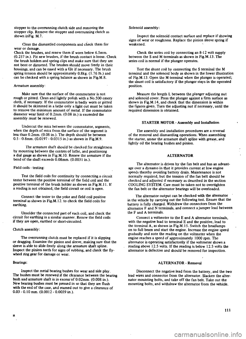
stopper
to
the
overrunning
clutch
side
and
removing
the
stopper
clip
Remove
the
stopper
and
overrunning
clutch
as
shown
inFig
M
7
Oean
the
dismantled
components
and
check
them
for
wear
or
damage
Cbeck
the
brushes
and
renew
them
if
worn
below
6
5mm
0
257
in
Fit
new
brushes
if
the
brush
contact
is
loose
Cbeck
the
brush
holders
and
spring
clips
and
make
sure
that
they
are
not
bent
or
distorted
The
brushes
should
move
freely
in
their
housings
and
can
be
eased
with
a
file
if
necessary
The
brush
spring
tension
should
be
approximately
0
8kg
1
76Ib
and
can
be
checked
with
a
spring
balance
as
shown
in
Fig
M
S
Armature
assembly
Make
sure
that
the
surface
of
the
commutator
is
not
rough
or
pitted
Oean
and
lightly
polish
with
a
No
500
emery
cloth
if
necessary
If
the
commutator
is
badly
worn
or
pitted
it
should
be
skimmed
in
a
lathe
only
a
light
cut
must
be
taken
to
remove
the
minimum
amount
of
metal
If
the
commutator
diameter
wear
limit
of
0
2mm
0
OS
in
is
exceeded
the
assembly
must
be
renewed
Undercut
the
mica
between
the
commutator
segments
when
the
depth
of
mica
from
the
surface
of
the
segment
is
less
than
0
2mm
0
08
in
The
depth
should
be
between
0
5
0
8mm
0
0197
0
0315
in
as
shown
in
Fig
M
9
The
armature
shaft
should
be
checked
for
straightness
by
mounting
between
the
centres
of
lathe
and
positioning
a
dial
gauge
as
shown
in
Fig
M
I
O
Renew
the
armature
if
the
bend
of
the
shaft
exceeds
0
08mm
0
0031
in
Field
coils
testing
Test
the
field
coils
for
continuity
by
connecting
a
circuit
tester
between
the
positive
terminal
of
the
field
coil
and
the
positive
terminal
of
the
brush
holder
as
shown
in
Fig
M
I
I
If
a
reading
is
not
obtained
the
field
circuit
or
coil
is
open
Cbnnect
the
tester
to
the
yoke
and
field
coil
positive
teoninal
as
shown
in
Fig
M
12
to
check
the
field
coils
for
earthing
Unsolder
the
connected
part
of
each
coil
and
check
the
circuit
for
earthing
in
a
similar
manner
Renew
the
field
coils
if
they
are
open
earthed
or
short
circuited
Outch
assembly
The
overrunning
clutch
must
be
replaced
if
it
is
slipping
or
dragging
Examine
the
pinion
and
sleeve
making
sure
that
the
sleeve
is
able
to
slide
freely
along
the
armature
shaft
spline
Inspect
the
pinion
teeth
for
signs
of
rubbing
and
check
the
fly
wheel
ring
gear
for
damage
or
wear
Bearings
Inspect
the
metal
bearing
bushes
for
wear
and
side
play
The
bushes
must
be
renewed
if
the
clearance
between
the
bearing
bush
and
armature
shaft
is
in
excess
of
0
02mm
0
008
in
New
bearing
bushes
must
be
pressed
in
so
that
they
are
flush
with
the
end
of
the
case
and
reamed
ou
t
to
give
a
clearance
of
0
03
0
10
mm
0
0012
0
0039
in
H
Solenoid
assembly
Inspect
the
solenoid
contact
surface
and
replace
if
showing
signs
of
wear
or
roughness
Replace
the
pinion
sleeve
spring
if
weakened
Check
the
series
coil
by
connecting
an
8
12
volt
supply
between
the
Sand
M
terminals
as
shown
in
Fig
M
13
The
series
coil
is
normal
if
the
plunger
operates
Test
the
shunt
coil
by
connecting
the
S
terminal
the
M
terminal
and
the
solenoid
body
as
shown
in
the
lower
illustration
of
Fig
M
13
Open
the
M
terminal
when
the
plunger
is
operated
the
shunt
coil
is
satisfactory
if
the
plunger
stays
in
the
operated
position
Measure
the
length
L
between
theylonger
adjusting
nut
and
solenoid
cover
Press
the
plunger
against
a
firm
surface
as
shown
in
Fig
M
14
and
check
that
the
dimension
is
within
the
figures
given
Turn
the
adjusting
nut
if
necessary
until
the
required
dimension
is
obtained
STARTER
MOTOR
Assembly
and
Installation
The
assembly
and
installation
procedures
are
a
reversal
of
the
removal
and
dismantling
operations
When
assembling
the
starter
smear
the
armature
shaft
spline
with
grease
and
lightly
oil
the
bearing
bushes
and
pinion
ALTERNATOR
The
alternator
is
driven
by
the
fan
belt
and
has
an
advant
age
over
a
dynamo
in
that
it
provides
current
at
low
engine
speeds
thereby
avoiding
battery
drain
Maintenance
is
not
normally
required
but
the
tension
of
the
fan
belt
should
be
checked
and
adjusted
if
necessary
as
described
in
the
section
COOLING
SYSTEM
Care
must
be
taken
not
to
overtighten
the
fan
belt
or
the
alternator
bearings
will
be
overloaded
The
alternator
output
can
be
checked
with
the
alternator
in
the
vehicle
by
carrying
out
the
following
test
Ensure
that
the
battery
is
fully
charged
Withdraw
the
connectors
from
the
alternator
F
and
N
terminals
and
connect
a
jumper
lead
between
the
F
and
A
terminals
Connect
a
voltmeter
to
the
E
and
A
alternator
terminals
with
the
negative
lead
to
terminal
E
and
the
positive
lead
to
the
terminal
A
as
shown
in
Fig
M
IS
Switch
the
headlamps
on
to
full
beam
and
start
the
engine
Increase
the
engine
speed
gradually
and
note
the
reading
on
the
voltmeter
when
the
engine
reaches
a
speed
of
approximately
lOaD
rpm
The
alternator
is
operating
satisfactorily
if
the
voltmeter
shows
a
reading
above
12
5
volts
If
the
reading
is
below
12
5
volts
the
alternator
is
defective
and
should
be
removed
for
inspection
ALTERNATOR
Removal
Disconnect
the
negative
lead
from
the
battery
and
the
two
lead
wires
and
connector
from
the
alternator
Slacken
the
alter
nator
mounting
bolts
and
take
off
the
fan
belt
Take
out
the
mounting
bolts
and
withdraw
the
alternator
from
the
vehicle
III
Page 130 of 171
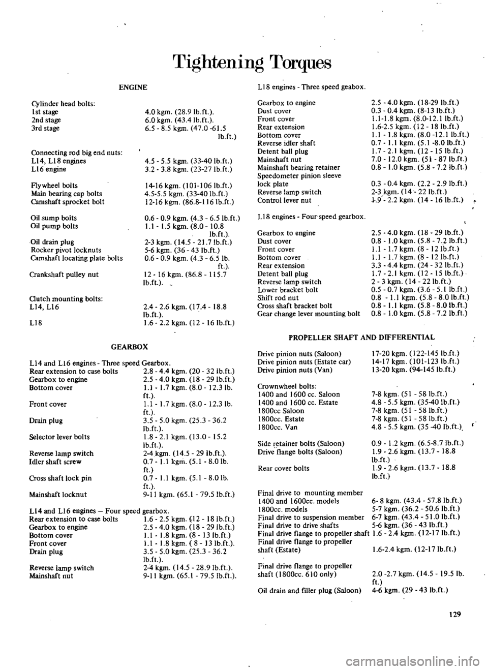
TIghtenIng
Torques
LIB
engines
Three
speed
geabox
ENGINE
2
5
4
0
kgm
18
29
Ib
ft
0
3
0
4
kgm
8
13
IbJI
Ll
1
8
kgm
8
0
12
llbJt
1
6
2
5
kgm
12
18Ib
ft
I
I
1
8
kgm
8
0
12
llbJt
0
7
I
I
kgm
5
1
8
0
IbJt
17
2
lkgm
l2
15IbJI
7
0
12
0
kgm
51
87IbJI
0
8
1
0
kgm
5
8
7
2
IbJI
0
3
0
4
kgm
2
2
2
9Ib
ft
2
3
kgm
14
22IbJI
J
9
2
2
kgm
14
16IbJI
Gearbox
to
engine
Dust
cover
Front
cover
Rear
extension
Bottom
cover
Reverse
idler
shaft
Detent
ball
plug
Mainshaft
nut
Mainshaft
bearing
retainer
Speedometer
pinion
sleeve
lock
plate
Reverse
lamp
switch
Control
lever
nut
Cylinder
head
bolts
1st
stage
2nd
stage
3rd
slage
4
0
kgm
28
9Ib
ft
6
0
kgm
43
4lb
ft
6
5
8
5
kgm
47
0
61
5
Ib
ft
Connecting
rod
big
end
nuts
Ll4
Ll8
engines
Ll6
engine
Flywheel
bolls
Main
bearing
cap
bolts
Camshaft
sprocket
bolt
4
5
5
5
kgm
33
40
Ib
fl
3
2
3
8
kgm
23
27
lb
ft
14
16
kgm
l01
106Ib
ft
4
5
5
5
kgm
33
40Ib
ft
12
16
kgm
86
8
116IbJt
0
6
0
9
kgm
4
3
6
5IbJt
I
I
1
5
kgm
8
0
10
8
Ib
fl
2
3
kgm
14
5
21
7Ib
ft
5
6
kgm
36
43
Ib
ft
0
6
0
9
kgm
4
3
6
5
Ib
ft
12
16kgm
86
8
115
7
IbJt
LIB
engines
Four
speed
gearbox
Oil
sump
bolts
Oil
pump
bolts
Oil
drain
plug
Rocker
pivot
locknuts
Camshaft
locating
plate
bolts
2
5
4
0
kgm
18
29
IbJt
0
8
1
0
kgm
5
8
7
2Ib
ft
Ll
l
7kgm
8
12IbJt
Ll
I
7kgm
8
12Ib
ft
3
3
44
kgm
24
32IbJI
1
7
2
1
kgm
12
15
IbJt
2
3
kgm
14
22Ib
ft
0
5
0
7
kgm
3
6
5
IlbJI
0
8
I
I
kgm
5
8
8
0Ib
ft
0
8
Ll
kgm
5
8
8
01b
ft
0
8
1
0
kgm
5
8
7
2Ib
ft
Gearbox
to
engine
Dust
cover
Front
cover
Bottom
cover
Rear
extension
Detent
ball
plug
Reverse
lamp
switch
Lower
bracket
bolt
Shift
rod
nut
Cross
shaft
bracket
bolt
Gear
change
lever
mounting
bolt
Crankshaft
pulley
nut
Outch
mounting
bolts
L14
Ll6
Ll8
2
4
2
6kgm
174
18
8
Ib
ft
1
6
2
2
kgm
12
16Ib
fl
PROPELLER
SHAFf
AND
DIFFERENTIAL
GEARBOX
17
20kgm
l22
145IbJI
14
17
kgm
101
123Ib
ft
13
20
kgm
94
145Ib
fI
Drive
pinion
nuts
Saloon
Drive
pinion
nuts
Estate
car
Drive
pinion
nuts
Van
Ll4
and
L16
engines
Three
speed
Gearbox
Rear
extension
to
case
bolts
2
8
4
4
kgm
20
32lb
ft
Gearbox
10
engine
2
5
4
0
kgm
18
29Ib
fI
Bnttom
cover
L1
1
7
kgm
8
0
12
3
lb
ft
Ll
1
7
kgm
8
0
12
3
lb
fl
3
5
5
0
kgm
25
3
36
2
Ib
ft
1
8
2
1
kgm
13
0
15
2
Ib
ft
2
4
kgm
14
5
29
Ib
ft
0
7
L1
kgm
5
1
8
0
lb
ft
0
7
Ll
kgm
5
1
8
0
lb
fl
9
11
kgm
65
1
79
51b
ft
Crown
wheel
bolts
1400
and
1600
cc
Saloon
1400
and
1600
cc
Eslale
1800ce
Saloon
I800cc
Estate
1800cc
Van
7
8
kgm
51
58Ib
ft
4
8
5
5
kgm
35
40
Ib
ft
7
8
kgm
51
58Ib
ft
7
8
kgm
51
58Ib
ft
4
8
5
5
kgm
35
40
Ib
ft
0
9
1
2
kgm
6
5
8
7Ib
ft
1
9
2
6
kgm
13
7
18
8
IbJI
1
9
2
6
kgm
13
7
18
8
Ib
f
Front
cover
Drain
plug
Selector
lever
bolts
Side
retainer
bolts
Saloon
Drive
flange
bolts
Saloon
Reverse
lamp
switch
Idler
shaft
screw
Rear
cover
bolts
Cross
shaft
lock
pin
Final
drive
to
mounting
member
1400
and
1600cc
models
6
8
kgm
43
4
57
8IbJI
1800cc
models
5
7
kgm
36
2
50
6Ib
fI
Final
drive
to
suspension
member
6
7
kgm
43
4
51
0
Ib
ft
Final
drive
to
drive
shafls
5
6
kgm
36
431b
ft
Final
drive
flange
to
propeller
shaft
1
6
2
4
kgm
12
17
Ib
ft
Final
drive
flange
to
propeller
shaft
Eslale
1
6
2
4
kgm
l2
17Ib
ft
Mainshafl
locknut
Ll4
and
L16
engines
Four
speed
gearbox
Rearexlension
to
case
bolts
1
6
2
5
kgm
12
18Ib
ft
Gearbox
to
engine
2
5
4
0
kgm
18
29Ib
ft
Bottnm
cnver
L1
1
8
kgm
8
13
Ib
ft
Fronl
cover
L1
1
8
kgm
8
13
IbJI
Drain
plug
3
5
5
0
kgm
25
3
36
2
Ib
f
2
4
kgm
14
5
28
9IbJt
9
11
kgm
65
1
79
5Ib
ft
Final
drive
flange
to
propeller
shaft
l800cc
610
only
Reverse
lamp
switch
Mainshaft
nut
2
0
2
7
kgm
14
5
19
5
lb
ft
4
6
kgm
29
43
Ib
ft
Oil
drain
and
flller
plug
Saloon
129
Page 131 of 171
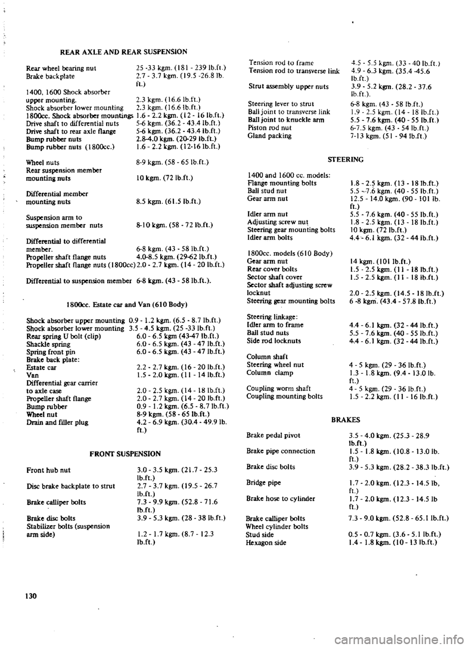
REAR
AXLE
AND
REAR
SUSPENSION
Rear
wheel
bearing
nut
Brake
backplate
25
33
kgm
181
239
IbJt
7
3
7
kgm
19
5
26
8
lb
ft
1400
1600
Shock
absorber
upper
mounting
3
kgm
l6
61b
ft
Shock
absorber
lower
mounting
3
kgm
16
6
Ih
ft
1800cc
Shock
absorber
mountings
1
6
2
2
kgm
12
161b
ft
Drive
shaft
to
differential
nuts
5
6
kgm
36
2
4341b
ft
Drive
shaft
to
rear
axle
flange
5
6
kgm
36
2
43
4lb
ft
Bump
rubber
nuts
2
8
4
0
kgm
20
29
Ib
ft
Bump
rubber
nuts
180Occ
1
6
2
2
kgm
12
16
Ib
ft
Wheel
nuts
Rear
suspension
member
mounting
nuts
8
9
kgm
58
651b
ft
10
kgm
72
Ib
ft
Differential
member
mounting
nuts
8
5
kgm
61
5Ib
ft
Suspension
arm
to
suspension
member
nuts
10
kgm
58
72
Ib
ft
Differential
to
differential
member
6
8
kgm
43
581b
fl
Propeller
shaft
flange
nuts
4
0
8
5
kgm
29
62
Ib
ft
Propeller
shaft
flange
nuts
I
800cc
2
0
2
7
kgm
14
201b
fl
Differential
to
suspension
member
6
8
kgm
43
58Ib
ft
1800cc
Estate
car
and
Van
610
Body
Shock
absorber
upper
mounting
0
9
1
2
kgm
6
5
8
7Ih
fl
Shock
absorber
lower
mounting
3
5
4
5
kgm
25
33Ib
ft
Rear
spring
U
bolt
clip
6
0
6
5
kgm
43
47
Ib
ft
Shackle
spring
6
0
6
5
kgm
43
47Ib
ft
Spring
front
pin
6
0
6
5
kgm
43
47Ib
ft
Brake
back
plate
Estate
car
Van
Differential
gear
carrier
to
axle
case
Propeller
shaft
flange
Bump
rubber
Wheel
nut
Drain
and
filler
plug
2
2
2
7
kgm
16
20IbJt
L5
2
0
kgm
II
14
Ib
ft
2
0
2
5
kgm
14
18Ib
ft
2
0
2
7kgm
14
20Ib
ft
0
9
1
2
kgm
6
5
8
7Ib
ft
9
kgm
58
65Ib
ft
4
2
6
9
kgm
30
4
49
9
lb
ft
FRONT
SUSPENSION
Front
hub
nut
3
0
3
5
kgm
21
7
25
3
Ib
ft
Disc
brake
backplate
to
strut
2
7
3
7
kgm
19
5
26
7
Ib
ft
Brake
ca1liper
bolts
7
3
9
9
kgm
52
8
71
6
Ib
ft
Brake
disc
bolts
3
9
5
3
kgm
28
381b
ft
Stabilizer
bolts
suspension
arm
side
1
2
I
7kgm
8
7
12
3
Ib
ft
130
Tension
rod
to
frame
Tension
rod
to
transverse
link
Strut
assembly
upper
nuts
Steering
lever
to
strut
Ball
joint
to
transverse
link
Ball
joint
to
knuckle
ann
Piston
rod
nut
Gland
packing
1400
and
1600
CC
models
Flange
mounting
bolts
Bali
stud
nut
Gear
ann
nut
Idler
ann
nut
Adjusting
screw
nut
Steering
gear
mounting
bolts
Idler
arm
bolts
1800cc
models
610
Body
Gear
ann
nut
Rear
cover
bolts
Sector
shaft
cover
Sector
shaft
adjusting
screw
locknut
Steering
gear
mounting
bolts
Steering
linkage
Idler
arm
to
frame
Ball
stud
nuts
Side
rod
locknuts
Column
shaft
Steering
wheel
nut
Column
clamp
COll
piing
worm
shaft
Coupling
mounting
bolts
Brake
pedal
pivot
Brake
pipe
connection
Brake
disc
bolts
Bridge
pipe
Brake
hose
to
cylinder
Brake
calliper
bolts
Wheel
cylinder
bolts
Stud
side
Hexagon
side
4
5
5
5
kgm
33
40Ib
ft
4
9
6
3
kgm
35
4
45
6
Ib
ft
3
9
5
2
kgm
28
2
37
6
Ib
fr
6
8
kgm
43
581b
ft
1
9
5
kgm
14
18Ib
fL
5
5
7
6
kgm
40
55Ib
ft
6
7
5
kgm
43
54Ib
ft
7
13
kgm
51
94Ib
ft
STEERING
1
8
2
5
kgm
13
18Ib
ft
5
5
7
6
kgm
40
55Ib
ft
12
5
14
0
kgm
90
101
lb
ft
5
5
7
6
kgm
40
55Ib
ft
1
8
2
5
kgm
13
18Ib
ft
10
kgm
72
Ib
ft
4
4
6
1
kgm
32
44Ib
ft
14
kgm
lOllb
ft
L5
2
5
kgm
II
18Ib
ft
1
5
2
5
kgm
II
18Ib
ft
2
0
2
5
kgm
14
5
18Ib
ft
6
8
kgm
43
4
57
8Ib
ft
4
4
6
1
kgm
32
44Ib
ft
5
5
7
6
kgm
40
55Ib
ft
4
4
6
1
kgm
32
44lb
ft
4
5
kgm
29
36
Ib
ft
1
3
1
8
kgm
9
4
13
0
lb
ft
4
5
kgm
29
36Ib
ft
L5
2
2
kgm
II
16Ib
ft
BRAKES
3
5
4
0
kgm
25
3
28
9
Ib
ft
1
5
1
8
kgm
10
8
13
0
lb
ft
3
9
5
3
kgm
28
2
38
3
IbJt
1
7
2
0
kgm
12
3
14
51b
fl
1
7
2
0
kgm
12
3
14
5lb
ft
7
3
9
0
kgm
52
8
65
llb
ft
0
5
0
7
kgm
3
6
5
llb
ft
1
4
1
8
kgm
10
13
Ib
ft
Page 134 of 171
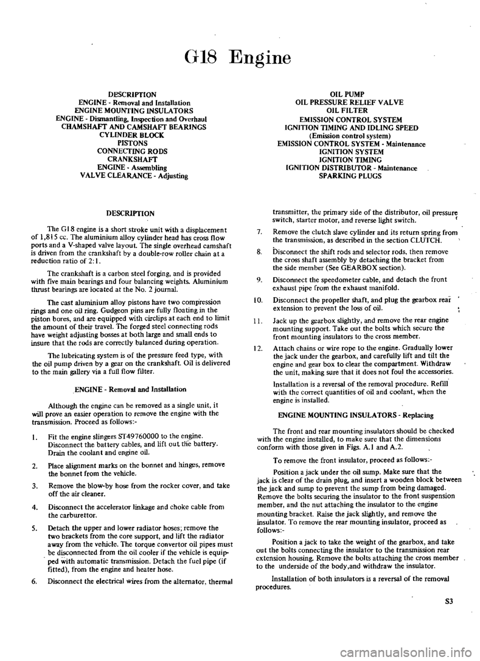
GIS
DESCRIYfION
ENGINE
Removal
and
Installation
ENGINE
MOUNTING
INSULATORS
ENGINE
Dismantling
Inspection
and
Overhaul
CHAMSHAFT
AND
CAMSHAFT
BEARINGS
CYLINDER
BLOCK
PISTONS
CONNECTING
RODS
CRANKSHAFT
ENGINE
Assembling
VALVE
CLEARANCE
Adjusting
DESCRIYfION
The
G
18
engine
is
a
short
stroke
unit
with
a
displacement
of
1
815
ce
The
aluminium
alloy
cylinder
head
has
cross
flow
ports
and
a
V
shaped
valve
layout
The
single
overhead
camshaft
is
driven
from
the
crankshaft
by
a
double
row
roller
chain
at
a
reduction
ratio
of
2
I
The
crankshaft
is
a
carbon
steel
forging
and
is
provided
with
five
main
bearings
and
four
balancing
weights
Aluminium
thrust
bearings
are
located
at
the
No
2
journal
The
cast
aluminium
alloy
pistons
have
two
comp
ression
rings
and
one
oil
ring
Gudgeon
pins
are
fully
floating
in
the
piston
bores
and
are
equipped
with
circlips
at
each
end
to
limit
the
amount
of
their
travel
The
forged
steel
connecting
rods
have
weight
adjusting
bosses
at
both
large
and
small
ends
to
insure
that
the
rods
are
correctly
balanced
during
operation
The
lubricating
system
is
of
the
pressure
feed
type
with
the
oil
pump
driven
by
a
gear
on
the
crankshaft
Oil
is
delivered
to
the
main
gallery
via
a
full
flow
ftlter
ENGINE
Removal
and
Installation
Although
the
engine
can
be
removed
as
a
single
unit
it
will
prove
an
easier
operation
to
remove
the
engine
with
the
transmission
Proceed
as
follows
Fit
the
engine
slingers
ST49760000
to
the
engine
Disconnect
the
battery
cables
and
lift
out
the
battery
Drain
the
coolant
and
engine
oil
2
Place
alignment
marks
on
the
bonnet
and
hinges
remove
the
bonnet
from
the
vehicle
3
Remove
the
blow
by
hose
from
the
rocker
cover
and
take
off
the
air
cleaner
4
Disconnect
the
accelerator
linkage
and
choke
cable
from
the
carburettor
S
Detach
the
upper
and
lower
radiator
hoses
remove
the
two
brackets
from
the
core
support
and
lift
the
radia
tor
away
from
the
vehicle
The
torque
convertor
oil
pipes
must
be
disconnected
from
the
oil
cooler
if
the
vehicle
is
equip
ped
with
automatic
transmission
Detach
the
fuel
pipe
if
fitted
from
the
engine
and
heater
hose
6
Disconnect
the
electrical
wires
from
the
alternator
thennal
EngIne
OIL
PUMP
OIL
PRESSURE
RELIEF
VALVE
OIL
FILTER
EMISSION
CONTROL
SYSTEM
IGNITION
TIMING
AND
IDLING
SPEED
Emission
control
system
EMISSION
CONTROL
SYSTEM
Maintenance
IGNITION
SYSTEM
IGNITION
TIMING
IGNITION
DISTRIBUTOR
Maintenance
SPARKING
PLUGS
transmitter
the
primary
side
of
the
distributor
oil
pressure
switch
starter
motor
and
reverse
light
switch
7
Remove
the
clutch
slave
cylinder
and
its
return
spring
from
the
transmission
as
described
in
the
section
CLUTCH
8
Disconnect
the
shift
rods
and
selector
rods
then
remove
the
cross
shaft
assembly
by
detaching
the
bracket
from
the
side
member
See
GEARBOX
section
9
Disconnect
the
speedometer
cable
and
detach
the
front
exhaust
pipe
from
the
exhaust
manifold
10
Disconnect
the
propeller
shaft
and
plug
the
gearbox
rear
extension
to
prevent
the
loss
of
oil
11
Jack
up
the
gearbox
slightly
and
remove
the
rear
engine
mounting
support
Take
out
the
bolts
which
secure
the
front
mounting
insulators
to
the
cross
member
12
Attach
chains
or
wire
rope
to
the
engine
Gradually
lower
the
jack
under
the
gearbox
and
carefully
lift
and
tilt
the
engine
and
gear
box
to
clear
the
compartment
Withdraw
the
unit
making
sure
that
it
does
not
foul
the
accessories
Installation
is
a
reversal
of
the
removal
procedure
RefIll
with
the
correct
quantities
of
oil
and
coolant
when
the
engine
is
installed
ENGINE
MOUNTING
INSULATORS
Replacing
The
front
and
rear
mounting
insulators
should
be
checked
with
the
engine
installed
to
make
sure
that
the
dimensions
conform
with
those
given
in
Figs
A
I
and
A
2
To
remove
the
front
insulator
proceed
as
follows
Position
a
jack
under
the
oil
sump
Make
sure
that
the
jack
is
clear
of
the
drain
plug
and
insert
a
wooden
block
between
the
jack
and
sump
to
prevent
the
sump
from
being
damaged
Remove
the
bolts
securing
the
insulator
to
the
front
suspension
member
and
the
nut
attaching
the
insulator
to
the
engine
mounting
bracket
Raise
the
jack
slightly
and
remove
the
insulator
To
remove
the
rear
mounting
insulator
proceed
as
follows
Position
a
jack
to
take
the
weight
of
the
gearbox
and
take
out
the
bolts
connecting
the
insulator
to
the
transmission
rear
extension
housing
Remove
the
bolts
attaching
the
cross
member
to
the
underside
of
the
body
and
withdraw
the
insulator
Installation
of
both
insulators
is
a
reversal
of
the
removal
procedures
S3
Page 142 of 171
pulley
should
be
aligned
with
the
T
mark
on
the
chain
cover
Install
the
cylinder
head
assembly
Coat
the
cylinder
block
side
of
the
head
gasket
with
sealing
agent
Three
Bond
No
4
or
equivalent
but
take
care
that
the
scaling
agent
does
not
enter
the
cylinders
Tighten
the
head
bolts
in
several
stages
to
a
torque
reading
of
8
0
to
9
0
kgrn
58
to
65
lb
ft
Tighten
the
bolts
to
the
sequence
shown
in
Fig
A
IB
Pull
the
timing
chain
out
of
the
chain
cover
and
set
it
on
the
camshaft
sprocket
so
that
the
timing
marks
are
aligned
then
place
the
sprocket
and
chain
on
the
camshaft
Install
the
distributor
drive
gear
on
the
camshaft
and
tighten
the
bolt
to
a
torque
reading
of
4
5
to
5
5
kgrn
32
6
to
39
8
lb
ft
Note
that
the
camshaft
bolt
has
a
left
hand
thread
Adjust
the
valve
clearances
as
described
under
the
appro
priate
heading
Fit
the
rubber
plugs
at
the
front
and
rear
of
the
cylinder
head
taking
care
to
apply
sealing
agent
to
the
rear
plug
Install
the
chain
adjusting
screw
and
adjust
the
tension
of
the
chain
in
the
following
manner
Rotate
the
crankshaft
clockwise
to
establish
the
correct
chain
tension
screw
the
adjusting
screw
fully
home
then
back
it
off
by
half
a
turn
and
secure
with
the
locknut
Install
the
valve
rocker
cover
and
fit
the
water
pump
Note
that
one
of
the
water
pump
mounting
bolts
also
secures
the
generator
adjusting
arm
Install
the
bracket
and
alternator
water
pump
pulley
fan
blades
and
fan
belt
Tighten
the
fan
bolts
and
lock
each
pair
of
bolts
together
using
wire
inserted
through
the
holes
provided
in
the
bolts
Install
the
oil
filter
and
fit
the
rocker
cover
hose
Install
the
distributor
so
that
the
vacuum
control
unit
and
rotor
arc
positioned
as
shown
in
Fig
A
19
Oil
the
distributor
driven
gear
Fit
the
breather
assembly
the
clamp
of
the
pipe
is
tightened
together
with
the
exhaust
manifold
Install
the
spark
plugs
and
connect
the
high
tension
leads
Install
the
exhaust
manifold
Fit
the
head
shield
plate
and
engine
slinger
and
tighten
them
together
Note
that
the
exhaust
manifold
gasket
must
be
fitted
with
the
steel
plate
facing
the
manifold
Install
the
clutch
as
described
in
the
section
CLUTCH
Remove
the
engine
from
the
mounting
stand
and
install
the
gearbox
intake
manifold
and
carburettor
stater
motor
engine
mounting
oil
pressure
warning
switch
etc
Fill
the
engine
and
gearbox
to
the
correct
levels
with
recommended
oils
and
refill
the
cooling
system
Adjust
the
ignition
timing
and
carburettor
as
described
in
the
appropriate
sections
VALVE
CLEARANCES
Adjusting
The
valves
clearances
can
be
adjusted
in
a
similar
manner
to
the
instructions
given
for
the
L14
LI6
L18
engines
Initially
adjust
the
clearances
with
the
engine
switched
off
and
cold
to
0
2
mm
0
0079
in
for
both
intake
and
exhaust
valves
Set
the
final
clearances
to
0
28
mm
0
011
in
for
both
intake
and
exhaust
valves
with
the
engine
warmed
up
to
its
normal
operating
temperature
OIL
PUMP
The
gear
type
oil
pump
is
chain
driven
from
a
sprocket
on
the
crankshaft
The
pump
can
be
removed
in
the
following
manner
1
Remove
the
sump
plug
and
drain
the
engine
oil
Remove
the
distributor
as
described
in
the
section
IGNITION
2
Remove
the
cylinder
head
assembly
fan
belt
crankshaft
pulley
and
oil
sump
3
Take
off
the
chain
cover
with
oil
fl
inger
4
Remove
the
oil
pump
and
crankshaft
sprockets
with
the
drive
chain
then
withdraw
the
pump
after
removing
the
four
mounting
bolts
Separate
the
cover
from
the
body
by
unscrewing
the
four
securing
bolts
and
withdraw
the
drive
and
idler
gear
assemblies
Unscrew
the
threaded
plug
and
take
out
the
relief
valve
and
spring
Clean
the
parts
thoroughly
and
inspect
them
four
signs
of
wear
or
damage
Check
the
following
clearances
Gear
backlash
0
1
to
0
5
mm
0
0039
to
0
0195
in
Side
clearance
between
gear
and
body
0
016
to
0
15
mm
0
0006
to
0
0059
in
Clearance
between
drive
shaft
and
body
0
016
to
0
1
mm
0
0006
to
0
0039
in
Clearance
between
drive
shaft
and
cover
0
02
to
0
1
mm
0
00078
to
0
0039
in
Clearance
between
idler
gear
and
idler
shaft
0
016
to
0
1
mm
0
0006
to
0
0039
in
Assembly
is
a
reversal
of
the
dismantling
procedures
taking
care
to
position
the
gears
so
that
the
dotted
mark
is
towards
the
cover
Install
the
pump
and
adjust
the
tension
of
the
drive
chain
by
ph
otting
the
pump
body
as
shown
in
Fig
A
20
When
the
chain
is
correctly
tensioned
it
should
be
capable
of
a
deflection
of
2
0
to
3
0
mm
0
079
to
0
118
in
as
indicated
OIL
PRESSURE
RELIEF
VALVE
The
pressure
relief
valve
shown
in
Fig
A
21
is
not
adjustable
This
valve
regulates
the
oil
pressure
to
4
55
4
85
kg
sq
cm
64
7
69
0
lb
sq
in
and
when
opened
allows
the
oil
to
by
pass
through
a
passage
in
the
pump
body
and
return
to
the
sump
Check
the
free
length
of
the
spring
which
should
be
64
0
to
66
0
mm
2
51
to
2
60
in
The
compressed
length
should
be
50
mm
at
7
8
to
9
7
kg
1
96
in
at
17
2
to
21
4Ibs
Renew
the
spring
if
necessary
OIL
FILTER
The
oil
filter
is
of
the
full
flow
type
with
a
replaceable
element
and
incorporates
a
by
pass
valve
in
the
cover
Oil
leaks
can
be
corrected
by
replacing
the
body
centre
shaft
or
cover
gaskets
The
body
and
centre
shaft
gaskets
should
always
be
renewed
after
dismantling
the
filter
S
1
Page 168 of 171
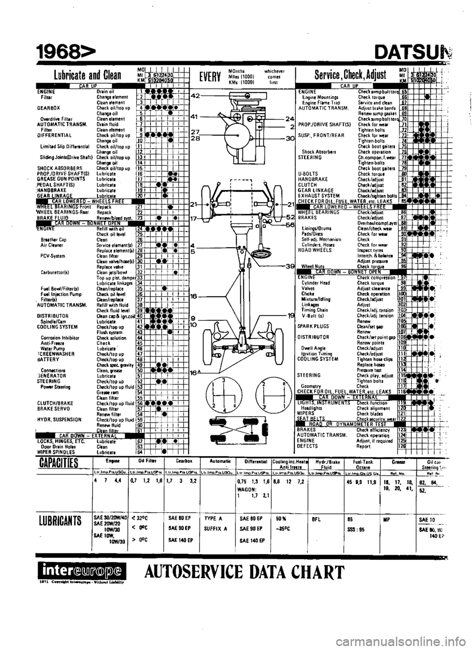
MO
MI
1224
D
I
KM
f
fMn
n
r
A
A
JP
I
I
T
I
I
I
Drain
ill
Changeelemenl
I
42
Cleantlement
3
I
II
r
I
Check
il
topup
4
I
Chinnloil
511
1
11
41
Gle
nelern
n
Ii
I
Orainlluid
7
I
I
I
I
Clunertmtn
81
1
I
I
I
I
I
27
Check
ailltop
up
Jf71
r
I
JIO
WI
28
Change
il
I
ill
limittdSlip
DiHlranti
1
Clleck
ilftopup
1J
I
I
I
Changelil
11
i
ill
ShdmgJolntt
Df
YlShlft
Check
11IIOpup
n
II
I
I
ChangeDl1
1
I
I
I
I
SHOCKASSORBERS
Check
Il
topup
5
PROP
DRIVESHAFTISI
lubncate
Hi
1
GREASE
GUN
POINTS
lubnCIl
it
PEOAlSHAFT
Sj
Lubrlc
te
18
HANDBHAKE
lubnc
1t
I
I
r
1
t
R
IINKAl
iF
luhncll
2u
I
I
i
I
ARlUWIORED
WHEELS
FREE
1m
I
I
i
1121
wHEE
L
tll
AHINli
ronl
HepitCk
211
t
f
WHEEl
BEARINGS
Rur
Repack
77
U
I
BRAKE
FLUID
R
nfWfbletd
1
I
lf
13
117
I
t
I
AH
UUWI
f
t1UN
11Itl
ih1tl
1
i
lcl
Check
oillevtl
B
l
r1i
BI1I1I1
r
Cap
Cleen
1ifj
j
I
Air
Cluner
Service
el
m
nt
l
J7
4
Replace
element
l
l
B
L
5
Cteenfilter
1
C
l
I
I
I
4
Clun
va
vellllR
I
I1
I
I
I
Repl
cH
lve
1
I
I
I
I
Cleen
jets
bOM
R
t
I
Top
liP
pisl
dempe
l
I
r
L
LlIbncatelinkages
I
I
L
Ctean
replace
5
j
I
Ch
ckoill
ve1
Ei
l
j
16
Clun
replac
n
11
R
fill
witll
fluid
38
I
Check
fluid
levll
IlL
t
I
CI
ign
toil
t
i
I
t
1
l
9
CheCk
top
u
p
10
Flulhryst
m
y
Cllecksolullon
44
Chltk
45
Lubrlc
tt
46
i
Clleck
top
up
L
L
Check
topup
4
aJdM
Cllltkspet
gl1vity
i
CI
en
gr
1S
liD
116
Lubriclt
1il
If
I
II
Clleck
topup
52
1
i
Chtck
topuplluid
3
I
I
Gre
rlm
4
I
1
I
I
I
Clunfiltlr
55
L
I
I
I
Chick
top
up
fluid
I6
w
W
e
I
ofi
Ldtir
1
Renewfiltlr
58
I
Check
topupflu
d
i91
i
I
i
Renrwfluid
I
I
I
I
I
ilinlil1r
11
I
I
I
I
I
I
CAR
DOWN
E
TERNAL
j
II
1
I
1
lOCKS
HINGES
Ell
Lubrictt
S21
r
1
el
L
Door
Dram
Hol
l
Clun
f
J
I
I
WIPER
SPINDLES
lubrictt
64
W
I
I
En
in
Dil
Filwr
GttrbOK
1968
Lubricate
and
Clean
ENGINE
Filt
r
GEARBOX
Dvttdrivt
Filt
r
AUTOMATIC
TRANSM
Filt
r
DIFFERENTIAL
PCV
Syllem
rburettor
s
FUll
Bowl
Filter
S1
Fu
llnjectionPump
Fittll
ll
AUTOMATIC
TRANSM
DISTRIBUTOR
Spindl
Ctm
COOLING
SYSTEM
CorrDlionlnllibitor
Anti
Frltl
W
t
rPump
CREENWASHER
ArrERY
Connections
3ENERATOR
STEERING
POMrStlering
CLUTCH
BRAKE
BRAKE
SERVO
HYDR
SUSPENSION
CAPACITIES
LUBRICANTS
Il
D
P
LUSClu
Service
Check
Adjust
CAR
UP
I
l
lletksumpbulttortM
1
Clled
rque
i6
ServiceJndclean
J1
Adjult
brake
bandl
tB
RtnMsumpgal
tt
fiS
Check
llJmpbnlttort
PROP
lOAIVE
SHAFT
S
Check
lor
wear
JJ
Tiglltenbolu
Jl
Check
tor
wear
n
Tiglltenboltl
Clllckbootgeiltrl
Clleckoperltion
Ch
CQmpon
l
welr
Tighten
bolts
Clleclbootgaiterl
Checktorqu
Gheck
edjult
Clllck
ljust
CIIRCk
adjult
Clleck
tighltnbolts
W
M
KSI
1
t
heCklMliiili
86
Check
ldjust
81
Overllllulcompl
rvll
Cleen
chltkwtlr
R9
Check
for
wear
0
Check
9
Checkforwp
lr
192
Il1Ipecttyrel
1IJ
Illte
II
blIl1nCl
Adjultpres
lure
Cllecktorul
liON
ET
OPE
l
heckcompression
Checktorqul
AdjUltclttr
nc
CheckoptTltion
Check
lIljLllt
AdjUlI
Clleck
alIj
tension
adj
t
nsion
I
Clun
selpp
jt1
Renew
Chetk
tPoint
tp
Renew
pointl
Check
6djult
110
J
Check
edjult
ill
i
ii
j
Tiglltenhoseclips
112
R
plece
lIastl
ill
PreSSIJ
test
114
1
STEERING
Clleek
play
adjust
ill
j
i
itl
e
Ti9htenboltl
ill
ii
Geometry
Check
U1L
H
CHECK
FOR
Oil
FUEL
WATER
etc
LEAKS
1181
I
I
R
DOWN
FXIE
HNA
11
1
1
lIGHTS
If
isfHUMt
NTS
Check
flll
C
lOn
f
3
Headlights
Checkllhgnmlnt
112Cr
WIPERS
Checkbladu
11111
J
TS
r
h
kIl
CII
I
Jrl7
iI
An
UH
OVNAUOMFTER
I
ST
I
BRAKES
CheCkemCienCY
1
I
AUTOMATIC
TRANSM
Clleek
op
rttioQ
T
ENGINE
Adjust
if
required
12
DEFECTS
Report
12
EVERY
MOnthl
Miles
1000
KMs
1000
lIBt
wtJichewl
ENGINE
EngmlMountings
Engine
Film
Trap
AUTOMATIC
TRANSM
24
2
30
SUSP
FRONT
REAR
Shock
Ablorb
rs
STEERING
1
21
5
1
c
e
U
80lTS
HANDBRAKE
CLUTCH
GEAR
LINKAGE
EXHAUST
SYSTEM
f
HFf
K
FOR
Oil
FllE
1
CAH
LUWI
RI
If
WHEEL
BEARINGS
BRAKES
UningsJDruml
Plds
Discl
Selhdj
Meclleni5l11
Cylinders
Hosel
ROAD
WHEELS
3S
Whe
1
Nun
AHllIIWN
ENGINE
Cyllnd
r
Held
Vllyes
Clloke
MiKtulli
ldling
linkagel
Timing
Ch
in
16
V
Belt
Is
SPARK
PLUGS
OISTRIBUTOR
Owell
Angle
Ignition
Timing
COOLING
SYSTEM
8
X
Automatic
Diffrrrntill
ICoolinginc
Ht
lltel
AntilrH1f
Ltr
lmoP
Ugo
IL
dmo
PII
U
Ou
HydrJBrak
Fluid
4
7
1
21
81
7
ULlma
II
USP
ULlmD
USP
L
L
tmoP
USQu
127
2
4
4
SAE
3O
2OW
411
SAE
lfrN
2fJ
IOWI3O
SAE1OW
IOW
30
320C
JOe
o
e
SAE80
EP
SAE90EP
SAE
140
EP
mmDIIIII
Ifn
c
ID
WIthDv
1
LI
obWt7
3
LtrJ
PtLUSPtL
3
2
0
75
T
3
1
8
B
8
WAGON
1
1
72
1
TYPE
A
SUFFIX
A
SAE80
EP
SAE90EP
SAE
140EP
0
aSoC
BFl
AUTOSERVICE
DATA
CHART
DATSUI
D
FurlT
nk
n
tln
G
0
Slltring
Re
I
lm
r
JSGI
11
1
No
4S
8
9
11
9
11
17
18
19
20
41
82
84
52
SSS
95
SAElll
SAE
80
c
14O