battery DATSUN 610 1969 Workshop Manual
[x] Cancel search | Manufacturer: DATSUN, Model Year: 1969, Model line: 610, Model: DATSUN 610 1969Pages: 171, PDF Size: 10.63 MB
Page 6 of 171
EngIne
INTRODUCTION
ENGINE
Removal
ENGINE
DismantUng
ENGINE
Inspection
and
Overhaul
VALVES
VALVE
GUIDES
VALVE
SEAT
INSERTS
CAMSHAFT
AND
CAMSHAFT
BEARINGS
Checking
CYliNDER
BLOCK
PtSTONS
AND
CONNECTING
RODS
INTRODUCTION
The
1400
1600
cc
and
1800
cc
engines
are
four
cylinder
in
line
units
with
a
single
overhead
camshaft
and
fully
balanced
five
bearing
crankshaft
The
valves
are
operated
through
rockers
which
are
directly
activated
by
the
earn
mechanism
The
crankshaft
is
a
special
steel
forging
with
the
centre
main
bearing
equipped
with
thrust
washers
to
take
up
the
end
thrust
of
the
crankshaft
The
special
aluminium
pistons
are
of
the
strut
construction
to
control
thermal
expansion
and
have
two
compression
rings
and
one
combined
oil
ring
The
gudgeon
pins
have
special
hollow
steel
shafts
and
are
a
fully
floating
fit
in
the
pistons
and
a
press
fit
in
the
connecting
rods
The
aluminium
alloy
cylinder
head
contains
wedge
type
combustion
chambers
and
is
fitted
with
aluminium
bronze
valve
seats
for
the
intake
valves
and
heat
resistant
steel
valve
seats
for
the
exhaust
valves
The
cast
iron
camshaft
is
driven
by
a
double
row
roller
chain
from
the
crankshaft
pulley
The
engine
is
pressure
lubricated
by
a
rotor
type
oil
pump
which
draws
oil
through
an
oil
strainer
into
the
pump
housing
and
then
forces
it
through
a
full
flow
oil
filter
into
the
main
oil
gallery
ENGINE
Removal
Place
alignment
marks
on
the
bonnet
and
hinges
remove
the
bonnet
from
the
vehicle
2
Drain
the
cooling
system
and
engine
and
transmission
lubricant
Remove
the
radiator
grille
3
Discon
ect
the
battery
cables
and
lift
out
the
battery
4
Detach
the
upper
and
lower
radiator
hoses
remove
the
radiator
mounting
bolts
and
lift
the
radiator
away
from
the
vehicle
The
torque
converter
c
jng
pipes
must
be
disconnected
from
the
radiator
on
vehicles
fitted
with
automatic
transmission
S
Remove
the
COOling
fan
and
pulley
disconnect
the
fuel
pipe
from
the
fuel
pump
and
the
heater
hoses
from
the
engine
attachments
6
Disconnect
the
accelerator
control
linkage
and
the
choke
CRANKSHAFT
AND
MAIN
BEARINGS
CAMSHAFT
AND
SPROCKET
FLYWHEEL
ENGINE
Assembling
VALVE
CLEARANCES
Adjusting
ENGINE
LUBRICATION
SYSTEM
OIL
PUMP
OIL
FILTER
CHANGING
THE
ENGINE
OIL
cable
from
the
carburettor
7
Disconnect
the
wirings
from
the
starter
alternator
ignition
coil
oil
pressure
switch
and
temperature
sender
unit
8
Remove
the
clutch
slave
cylinder
Fig
A
2
and
its
return
spring
9
Disconnect
the
speedometer
cable
and
withdraw
the
plug
connector
from
the
reversing
light
switch
10
Disconnect
the
shift
rods
and
seJector
rods
and
remove
the
cross
shaft
assembly
as
described
in
the
section
Gear
box
II
Disconnect
the
front
exhaust
pipe
from
the
exhaust
manifold
disconnect
the
centre
pipe
from
the
rear
pipe
and
remove
the
front
pipe
pre
muffler
and
centre
pipe
assembly
12
Disconnect
the
propeUer
shaft
flange
from
the
companion
flange
from
the
gear
carrier
13
Jack
up
the
gearbox
slightly
and
remove
the
rear
engine
mounting
bracket
bolts
remove
the
mounting
cross
member
and
handbrake
cable
c1amp
14
Remove
the
bolts
securing
the
front
engine
mounting
brackets
to
the
crossmember
15
Attach
lifting
cable
or
chains
to
the
hooks
installed
at
the
front
and
rear
of
the
cylinder
head
Lower
the
jack
under
the
gearbox
and
carefully
lift
and
tilt
the
engine
and
gearbox
unit
Withdraw
the
engine
and
gearbox
from
the
compartment
making
sure
that
it
is
guided
past
the
accessories
installed
on
the
body
ENGINE
Dismantling
Remove
the
engine
as
previously
described
and
carefully
clean
the
exterior
surfaces
Cbeck
for
signs
of
fuel
oil
or
water
leaks
past
the
cylinder
head
and
block
Remove
the
air
cleaner
alternator
distributor
and
starter
motor
Plug
the
carburettor
air
horn
and
distributor
hole
to
prevent
the
ingress
of
foreign
matter
Remove
the
gearbox
from
the
engine
drain
the
engine
oil
and
coolant
Mount
the
engine
in
a
suitable
stand
the
special
engine
attachment
ST05260001
and
engine
ST0501SOO0
should
be
used
if
available
Fig
A
3
5
Page 30 of 171
IgnItIon
System
DESCRII
TION
IGNITION
TIMING
IGNITION
DISTRIBUTOR
Maintenance
ADJUSTING
THE
CONTACT
BREAKER
GAP
CENTRIFUGAL
ADVANCE
MECHANISM
VACUUM
ADVANCE
MECHANISM
IGNITION
DISTRIBUTOR
Removal
and
Dismantling
IGNITION
DISTRIBUTOR
Assembling
and
Installation
SPARKING
PLUGS
DESCRII
TION
The
ignition
circuit
comprises
the
distributor
ignition
coil
ignition
switch
spark
plugs
high
tension
lead
and
the
battery
See
Fig
C
1
The
Hitachi
distributor
is
shown
in
exploded
form
in
Fig
C
2
19niton
timing
is
automatically
regulated
by
the
distributor
centrifugal
advance
mechanism
or
vacuum
advance
mechanism
depending
upon
the
demand
made
on
the
engine
The
vacuum
advance
mechanism
operates
under
part
throttle
only
and
uses
intake
manifold
depression
to
advance
the
ignition
timing
When
the
engine
speed
is
increased
the
vacuum
is
inoperative
and
ignition
timing
is
regulated
by
the
centrifugal
advance
mechanism
The
centrifugal
advance
mechanism
uses
a
system
of
governor
weights
and
springs
which
turn
the
carn
assembly
in
on
anti
clockwise
direction
to
advance
the
ignition
timing
As
the
engine
speed
is
decreased
the
weights
move
back
and
allow
the
cam
to
return
thereby
retarding
the
ignition
timing
The
ignition
coil
is
an
oil
filled
unit
comprising
a
coil
around
which
is
wound
the
secondary
and
primary
windings
The
number
of
turns
in
the
primary
winding
provide
a
high
secondary
voltage
throughout
the
speed
range
The
resistor
is
automatically
by
passed
at
the
moment
of
starting
and
allows
the
ignition
coil
to
be
directly
connected
to
the
battery
This
applies
the
full
battery
voltage
to
the
coil
to
give
the
necessary
staTting
boost
When
the
starter
switch
is
released
the
current
flows
through
the
resistor
and
the
voltage
through
the
coil
is
dropped
for
normal
running
purposes
IGNITION
TIMING
The
ignition
timing
can
be
accurately
checked
using
a
stroboscopic
timing
light
which
should
be
connected
in
accor
dance
with
the
manufacturers
instructions
Make
sure
that
the
timing
marks
on
the
crankshaft
pulley
are
visible
if
they
are
not
visible
mark
them
with
chalk
or
white
paint
Each
mark
represents
a
50
division
of
the
crank
angle
Disconnect
the
distributor
vacuum
line
start
the
engine
and
allow
it
to
run
at
normal
idling
speed
or
slightly
below
Point
the
timing
light
at
the
timing
pointer
on
the
front
cover
Fig
C
3
The
crankshaft
pulley
groove
should
appear
to
be
stationery
and
aligned
with
the
pointer
on
the
front
cover
The
top
dead
centre
mark
is
located
at
the
extreme
right
as
shown
in
the
illustration
If
the
setting
requires
adjustment
the
distributor
flange
bolts
must
be
slackened
and
the
distributor
body
turned
clockwise
to
advance
or
anti
clockwise
to
retard
the
timing
See
Technical
Data
for
timing
settings
After
adjusting
the
timing
tighten
the
distributor
flange
bolts
and
recheck
the
timing
IGNITION
DISTRIBUTOR
Maintenance
Remove
the
distributor
cap
by
easing
away
the
two
clamps
and
examine
the
points
for
signs
of
burning
or
pitting
The
points
can
be
cleaned
if
necessary
using
a
fine
grade
of
oilstone
or
file
The
faces
of
the
points
must
be
completely
flat
and
parallel
and
all
abrasive
dust
removed
with
compressed
air
If
the
points
are
excessively
pitted
they
must
be
renewed
and
grease
applied
to
the
moving
contact
pivot
and
the
surface
of
the
cam
Ensure
that
the
distributor
cap
is
thoroughly
clean
both
inside
and
outside
A
contaminated
cap
will
promote
tracking
indicated
by
black
lines
and
caused
by
electrical
leakage
between
the
segments
on
the
inside
of
the
cap
Make
sure
that
the
carbon
button
is
not
worn
Both
the
distributor
cap
and
rotor
must
be
renewed
if
they
are
cracked
or
damaged
IGNITION
DISTRIBUTOR
Adjusting
the
contact
breaker
gap
To
adjust
the
contact
breaker
points
remove
the
distributor
cap
and
pull
the
rotor
off
the
cam
spindle
Turn
the
engine
until
the
heel
of
the
contact
breaker
arm
is
positioned
on
the
cam
lobe
the
contact
breaker
gap
is
set
to
the
maximum
in
this
position
Slacken
the
adjusting
screw
Fig
CA
insert
a
feeler
gauge
between
the
points
and
adjust
the
breaker
plate
until
the
re
quired
gap
of
0
45
0
55
mm
0
0177
0
0217
in
is
obtained
Tighten
the
adjusting
screw
and
recheck
the
setting
After
the
contact
breaker
gap
has
been
adjusted
check
the
ignition
timing
as
previously
described
The
tension
of
the
contact
breaker
should
be
0
5
0
65
kg
I
I
I
4
lb
Measure
the
tension
with
a
gauge
and
at
900
to
the
contact
breaker
arm
29
Page 32 of 171
CENTRIFUGAL
ADVANCE
MECHANISM
Special
equipment
is
required
to
check
the
advance
characteristics
It
is
possible
however
to
carry
out
an
exam
ination
of
the
caffi
assembly
and
the
weights
and
springs
to
ensure
that
the
earn
is
not
seizing
Lift
off
the
distributor
cap
and
turn
the
rotor
anti
clock
wise
When
the
rotor
is
released
is
should
return
to
the
fully
retarded
position
without
sticking
If
it
does
not
return
to
the
fully
retarded
position
it
will
be
necessary
to
check
for
dirt
and
weak
springs
It
should
be
noted
that
any
wear
in
the
mechanism
or
lose
of
spring
tension
will
upset
the
advance
characteristics
and
cause
unsatisfactory
engine
running
performance
over
the
speed
range
VACUUM
ADVANCE
MECHANISM
The
diaphragm
of
the
vacuum
advance
mechanism
is
mechanically
connected
to
the
contact
breaker
plate
The
rise
and
fall
of
inlet
manifold
depression
causes
the
diaphragm
to
move
the
contact
breaker
plate
to
advance
or
retard
the
ignition
If
the
vacuum
control
unit
fails
to
function
correctly
a
check
can
be
carried
out
to
ensure
that
the
contact
breaker
plate
is
moving
freely
and
that
the
three
steel
balls
at
the
top
and
oottom
of
the
plate
are
adequately
lubricated
Also
make
sure
that
the
vacuum
inlet
pipe
is
not
blocked
or
leaking
and
is
securely
tightened
Leakage
may
be
due
to
a
defective
diaphragm
which
should
be
renewed
along
with
any
other
faulty
part
of
the
mechanism
IGNITION
DlSTRffiUTOR
Removal
and
Dismantling
Disconnect
the
battery
leads
2
Disconnect
the
high
tension
lead
at
the
coil
3
Withdraw
the
high
tension
leads
from
the
distributor
cap
4
Detach
the
suction
pipe
from
the
vacuum
control
unit
5
Mark
the
position
of
the
distributor
and
rotor
remove
the
flange
mounting
bolts
and
withdraw
the
distributor
To
dismantle
the
distributor
proceed
as
follows
Take
off
the
distributor
cap
and
remove
the
rotor
Slacken
the
two
set
screws
holding
the
contact
breaker
upper
plate
Remove
the
primary
cable
terminals
and
withdraw
the
contact
set
from
the
distributor
Fig
C
S
Remove
the
vacuum
control
unit
c
Remove
the
two
screws
and
lift
out
the
contact
breaker
plate
detach
the
clamp
the
terminal
and
the
lead
To
remove
the
cam
take
out
the
centre
screw
as
shown
in
Fig
e
6
Drive
out
the
drive
pinion
retaining
pin
with
a
drift
and
hammer
Fig
e
and
remove
the
pinion
and
washer
Take
care
not
to
stretch
or
deform
the
governor
springs
when
detaching
them
from
the
weights
IGNITION
DISTRIBUTOR
Assembling
and
Installing
Assembly
is
a
reversal
of
the
dismantling
procedure
Lubricate
the
moving
contact
pivot
and
smear
the
lobes
of
the
cam
with
multi
purpose
grease
If
the
centrifugal
advance
mechanism
has
been
dismantled
the
governor
springs
and
cams
must
be
refitted
as
shown
in
Fig
e
8
The
governor
weight
pin
6
should
be
fitted
into
the
longer
of
the
two
slots
leaving
a
certain
amount
of
clearance
for
the
start
and
end
of
the
centrifugal
advance
movement
When
installing
the
distributor
take
care
to
align
the
body
and
rotor
with
the
marks
made
during
removal
The
rotor
must
be
positioned
in
its
original
location
it
will
turn
slightly
when
the
distributor
is
inserted
and
the
gear
teeth
mesh
Remove
and
replace
the
distributor
if
the
rotor
does
not
point
to
the
align
ment
mark
until
both
distributor
body
and
rotor
are
correctly
aligned
SPARKING
PLUGS
The
sparking
plugs
should
be
inspected
and
cleaned
at
regular
intervals
not
exceeding
every
10
000
km
6000
miles
New
sparking
plugs
should
be
fitted
at
approximately
20
000
km
12
000
miles
Remove
the
plugs
and
check
the
amount
of
electrode
wear
and
type
of
deposits
Brown
to
greyish
tan
deposits
with
slight
electrode
wear
indicate
that
the
plugs
are
satisfactory
and
working
in
the
correct
heat
range
Dry
fluffy
carbon
deposits
are
caused
by
too
rich
a
mixture
dirty
air
cleaner
excessive
idling
or
faulty
ignition
In
this
case
it
is
advisable
to
replace
the
plugs
with
plugs
having
a
higher
heat
range
Oily
wet
black
deposits
are
an
indication
of
oil
in
the
combustion
chambers
through
worn
pistons
and
rings
or
excessive
clearance
between
valve
guides
and
stems
The
engine
should
be
overhauled
and
hotter
plugs
installed
A
white
or
light
grey
centre
electrode
and
bluish
burned
side
electrode
indicates
engine
overheating
incorrect
ignition
timing
loose
plugs
low
fuel
pump
pressure
or
incorrect
grade
of
fuel
Colder
sparking
plugs
should
be
fitted
The
plugs
should
be
cleaned
on
a
blasting
machine
and
tested
Dress
the
electrodes
with
a
small
file
so
that
the
surfaces
of
both
electrodes
are
flat
and
parallel
Adjust
the
spark
plug
gap
to
0
8
0
9
mm
0
031
0
035
in
by
bending
the
earth
electrode
Refit
the
plugs
and
tighten
them
to
a
torque
reading
of
1
5
2
5
kgm
II
15Ib
ft
31
Page 92 of 171
SteerIng
DEsn
IPTION
S
i
EERlNG
MaintenaDce
STEERING
WHEEL
AND
STEERING
GEAR
Removal
and
Installation
STEERING
GEAR
Dismantling
STEERING
GEAR
Inspection
and
Adjustment
DESCRIPTION
A
worm
and
recirculating
ball
type
steering
system
is
fitted
to
the
vehicle
the
component
parts
of
the
steering
gear
are
shown
in
Fig
K
I
The
steering
linkage
consists
of
the
centre
tie
rod
pitman
ann
idler
arm
outer
tie
rods
and
the
knuckle
arms
as
shown
in
Fig
K
2
A
collapsible
steering
column
assembly
can
be
fitted
to
the
vehicle
to
protect
the
driver
from
injury
in
a
head
on
collision
Details
of
this
type
of
assembly
are
given
under
the
appropriate
heading
STEERING
Maintenance
O1eck
the
oil
level
in
the
steering
box
every
10
000
km
6
000
miles
and
top
up
with
recommended
lubricant
if
necessary
Grease
the
steering
linkage
every
50
000
km
30
OOO
miles
It
will
be
necessary
to
replace
the
plug
in
the
tie
rod
ball
joints
with
a
grease
nipple
for
this
operation
as
previously
described
in
the
section
FRONT
SUSPENSION
Use
a
grease
gun
to
completely
replace
the
old
grease
with
new
grease
making
SUfe
that
the
grease
is
not
forced
from
under
the
cover
clamp
if
a
high
pressure
gun
is
used
STEERING
WHEEL
AND
STEERING
GEAR
Removal
1
Take
out
the
retaining
bolts
and
remove
the
horn
ring
remove
the
steering
wheel
nut
Fig
K
3
and
pull
off
the
steering
wheel
The
special
tool
ST
27180000
should
be
used
if
available
2
Disconnect
the
battery
leads
remove
the
steering
column
shell
covers
and
the
turn
signal
and
lighting
switch
assembly
3
On
vehicles
fitted
with
steering
column
gear
change
assemblies
the
gear
lever
must
be
removed
from
the
control
rod
assembly
Unscrew
the
retaining
boltg
and
disconnect
the
gear
lever
4
Remove
the
bolts
from
the
steering
column
upper
clamp
Fig
K
4
and
the
bolts
holding
the
lower
plate
Fig
K
5
5
If
the
vehicle
is
fitted
with
steering
column
gear
change
remove
the
cotterpin
from
the
trunnion
and
detach
the
gearchange
rod
and
selector
rod
from
the
change
lever
and
selector
lever
STEERING
GEAR
Assembly
and
Adjustment
COLLAPSIBLE
STEERING
COLLAPSIBLE
STEERING
Removal
and
Inspection
COLLAPSIBLE
STEERING
Installation
STEERING
LINKAGE
6
Remove
the
bolts
securing
the
steering
gear
housing
to
the
car
body
Fig
K
6
and
pull
the
steering
gear
towards
the
engine
compartment
Remove
the
gearchange
control
from
the
steering
gear
assembly
as
described
in
the
section
GEARBOX
STEERING
WHEEL
AND
STEERING
GEAR
Installation
Installation
is
a
reversal
of
the
removal
procedure
When
the
installation
has
been
completed
make
sure
that
the
steering
wheel
can
be
turned
smoothly
and
is
correctly
aligned
The
free
travel
of
the
steering
wheel
should
be
between
2S
30mm
0
9B
1
18
in
Tighten
the
steering
wheel
locknut
to
a
torque
reading
of
4
0
5
0
kgm
29
36Ib
ft
and
the
steering
column
upper
clamp
and
plate
bolts
to
a
torque
reading
of
1
3
1
8
kgm
94
1
3
Ib
ft
Ensure
that
the
steering
box
is
topped
up
to
the
correct
level
with
recommended
lubricant
STEERING
GEAR
Dismantling
Remove
the
pitman
arm
retaining
nut
and
pull
out
the
arm
The
special
puller
ST
27140000
should
be
used
if
available
Remove
the
drain
plug
from
the
steering
gear
housing
and
drain
the
oil
Slacken
the
adjusting
screw
nut
and
turn
the
sector
shaft
adjusting
screw
a
few
turns
in
the
anti
clockwise
direction
Remove
the
sector
shaft
cover
retaining
bolts
and
pull
the
sector
shaft
cover
and
sector
shaft
from
the
gear
housing
Fig
K
7
Remove
the
bolts
securing
the
column
jacket
to
the
gear
housing
and
carefully
withdraw
the
main
column
jacket
assembly
from
the
gear
housing
Fig
K
B
NOTE
The
ball
must
not
be
allowed
to
run
to
either
end
of
the
worm
or
the
ends
of
the
ball
guides
will
be
damaged
Pull
the
column
assembly
from
the
column
jacket
Remove
the
sector
shaft
oil
seal
and
take
out
the
rear
bearing
outer
race
from
the
column
jacket
with
a
suitable
puller
Withdraw
the
bearing
inner
races
from
the
front
and
fear
worm
bearings
Remove
the
column
shaft
bearing
91
Page 96 of 171
the
system
operates
smoothly
COLLAPSIBLE
STEERING
The
collapsible
steering
column
is
designed
so
that
compression
occurs
when
the
vehicle
is
involved
in
a
head
on
collision
See
Fig
K
13
Two
forces
can
be
considered
when
a
collision
of
this
type
takes
place
These
being
the
primary
force
in
which
the
forward
motion
of
the
car
is
suddenly
halted
and
the
secondary
force
as
the
driver
continues
in
a
forward
direction
onto
the
steering
wheel
and
column
The
collapsible
column
is
designed
so
that
it
does
not
move
to
the
rear
i
e
into
the
driving
com
partment
when
the
primary
force
or
forward
motion
of
the
car
is
suddenly
halted
When
the
secondary
force
takes
place
as
the
driver
is
thrown
forward
the
column
jacket
gradually
collapses
and
partially
absorbs
the
amount
of
impact
The
collapsible
type
of
column
is
no
more
susceptible
to
damage
than
an
ordinary
column
when
it
is
installed
in
the
vehicle
however
when
a
collapsible
column
is
removed
it
must
be
carefully
handled
A
sharp
blow
on
the
end
of
the
shaft
or
gear
change
levers
dropping
or
leaning
on
the
assembly
can
cause
the
column
jacket
to
bend
particularly
at
the
bellows
part
which
absorbs
the
shock
The
steering
movement
is
transmitted
by
the
lower
shaft
and
upper
tube
The
lower
shaft
exterior
and
upper
tube
interior
are
tightly
fitted
together
with
four
plastic
pins
com
pletely
eliminating
any
gap
When
a
collision
occurs
the
plastic
pins
shear
and
the
lower
shaft
enters
the
upper
tube
this
action
will
cause
the
shaft
end
to
spread
and
the
lower
shaft
cannot
then
be
withdrawn
unless
an
extremely
high
load
is
applied
The
shaft
is
prevented
from
moving
towards
the
drivers
compartment
when
the
primary
force
takes
place
i
e
when
the
forward
motion
of
the
vehicle
is
suddenly
halted
by
the
three
stoppers
on
the
jacket
tube
The
steering
lock
collar
mounted
to
the
shaft
contacts
the
stoppers
and
prevents
a
rear
ward
movement
A
part
of
the
jacket
tube
is
specially
formed
to
act
as
an
energy
absorbing
part
of
the
collapsible
steering
The
upper
and
lower
guide
tubes
joined
with
polyacetal
resin
are
inserted
into
the
mesh
tube
so
that
energy
generated
by
a
collision
can
be
absorbed
as
smoothly
as
possible
with
a
low
load
The
steering
column
clamp
shown
in
Fig
K
14
is
secured
to
the
jacket
tube
and
body
by
bolts
with
two
aluminium
slidings
blocks
set
to
the
body
by
plastic
pins
An
impact
from
the
drivers
side
causes
the
plastic
pins
to
shear
and
leave
the
sliding
block
in
the
column
clamp
side
allowing
the
clamp
to
move
with
the
jacket
as
it
collapses
COLLAPSffiLE
STEERING
Removal
and
Inspection
Steering
Wheel
I
Disconnect
the
battery
earth
cable
2
Disconnect
the
horn
wiring
and
remove
the
horn
pad
3
Remove
the
steering
wheel
nut
using
the
special
puller
ST
27180000
Eig
K
15
Remove
the
column
shell
covers
Fig
K
16
and
the
turn
signal
switch
assembly
Column
shaft
4
Remove
the
cotter
pin
and
detach
the
shift
rod
Automatic
Transmission
Remove
the
bolt
securing
the
worm
shaft
and
coupling
Fig
K
17
5
Take
out
the
bolts
securing
the
column
tube
flange
to
the
dash
panel
and
the
bolts
securing
the
column
clamp
With
draw
the
steering
column
shaft
towards
the
car
interior
A
careful
check
should
be
made
to
ensure
that
the
assembly
is
not
damaged
in
any
way
Pull
out
the
lower
shaft
tap
the
column
clamp
towards
the
steering
wheel
end
and
remove
the
screws
securing
the
upper
and
lower
tubes
Separate
the
upper
and
lower
tubes
Remove
the
snap
ring
from
the
upper
end
of
the
column
pull
the
upper
jacket
down
and
separate
it
from
the
upper
jacket
tube
Take
care
not
to
damage
the
bearing
Remove
the
plain
washer
and
spring
from
the
upper
shaft
Check
the
column
bearings
for
damage
and
lack
of
smooth
ness
Apply
multi
purpose
grease
to
the
bearing
if
necessary
Inspect
the
jacket
tubes
for
signs
of
deformation
renew
the
tubes
if
necessary
Check
the
dimension
A
in
Fig
K
1B
to
make
SUfe
that
the
jacket
has
not
been
crushed
Check
the
dimension
B
Fig
K
14
COLLAPSffiLE
STEERING
Assembly
and
Installation
Assembly
is
a
reversal
of
the
dismantling
procedure
noting
the
following
points
Lubricate
the
column
bearing
the
spring
and
dust
seal
sliding
parts
Ensure
that
the
upper
shaft
steering
lock
hole
and
the
steering
lock
are
correctly
positioned
Fig
K
19
When
assembling
the
lower
shaft
take
care
to
coincide
the
notch
on
the
universal
joint
with
the
punched
mark
on
the
shaft
Coat
the
upper
and
lower
shaft
serrations
with
multi
purpose
grease
Set
the
steering
in
the
straight
ahead
position
and
fit
the
column
shaft
to
the
steering
gear
See
Fig
K
20
Insert
the
column
through
the
dash
board
and
install
it
to
the
gear
so
that
the
punch
mark
at
the
top
of
the
shaft
is
forced
upwards
Slide
the
universal
joint
to
the
steering
gear
and
temporarily
install
the
column
clamp
6
Fit
the
lower
cover
flange
7
and
tighten
the
column
clamp
bolts
Check
the
steering
wheel
alignment
with
the
wheels
in
the
straight
ahead
position
If
the
steering
wheel
and
steering
lock
are
misaligned
by
more
than
35
mm
I
4
in
from
the
vertical
position
femove
the
steering
wheel
and
re
centre
it
STEERING
LINKAGE
Removal
Jack
up
the
front
of
the
vehicle
and
support
it
on
stands
2
Remove
the
cotterpins
and
castle
nuts
fastening
the
tie
rod
ball
joints
to
the
knuckle
arms
95
Page 109 of 171
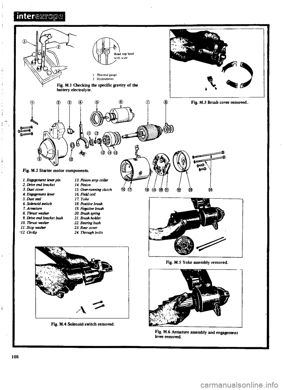
interQ
8
j
@W
2
m
tV
r
ReJld
cop
level
th
elk
FIg
M
I
llIecking
the
specific
gra
ity
of
the
battery
electrolyte
I
Thermal
u
e
Hydrometer
f
j
0
l
Q
I
iJ
Qy@
I
@
@
@
ti
II
@
@
Fig
M
3
Brush
cover
removed
j
i
Fill
M
2
Starter
motor
components
1
L
u
uJIner
pin
2
Drive
mil
Nack
t
3
Dult
COPD
4
E
mmtle
r
5
Aut
mzl
6
Solmoid
mlch
7
Arm
zturr
8
Thnut
9
IJriv
mil
blllck
t
bush
10
17uust
WdSMr
11
Stop
washer
12
CiTc
ip
13
PirUon
srap
collar
14
Pinion
IS
IWfni1l6
clutch
16
Field
coil
17
Yok
18
Politive
brwh
19
N
J1iP
bnuh
20
Bnuh
rprinK
21
Brullr
holder
22
Bearing
bwh
23
Rmr
COJIU
24
Through
botrr
@
FIg
M
5
Yoke
assembly
removed
Fill
M
4
Solenoid
switch
1
108
Fig
M
6
Annatore
assembly
and
engagemenr
lever
removed
Page 110 of 171
ElectrIcal
EquIpment
DESCRIPTION
BATTERY
Maintenance
STARTER
MOTOR
Removal
and
Dismantling
STARTER
MOTOR
Testing
STARTER
MOTOR
Assembly
and
Installation
ALTERNATOR
Removal
Dismantling
and
Inspection
DESCRIPTION
A
12
volt
negative
earth
electrical
system
is
used
in
which
the
battery
is
charged
by
an
alternator
In
the
alternator
a
magnetic
field
is
produced
by
the
rotor
which
consists
of
the
alternator
shaft
field
coil
p
le
pieces
and
slip
rings
Output
current
is
generated
in
the
armature
coils
located
in
the
stator
Six
silicon
diodes
are
incorporated
in
the
alternator
caSing
to
rectify
the
alternating
current
supply
A
voltage
regulator
and
pilot
lamp
relay
are
built
in
the
regulator
box
which
nonnally
does
not
give
trouble
or
require
attention
The
starter
motor
is
a
brush
type
series
wound
motor
in
which
positive
meshing
of
the
pinion
and
ring
gear
teeth
are
secured
by
means
of
an
overrunning
clutch
BATTERY
Maintenance
The
battery
should
be
maintained
in
a
clean
and
dry
condition
at
all
times
or
a
current
leakage
may
occur
between
the
terminals
If
frequent
topping
up
is
required
it
is
an
indication
of
overcharging
or
deterioration
of
the
battery
When
refitting
the
cables
clean
them
thoroughly
and
coat
their
terminals
and
the
terminal
posts
with
petroleum
jelly
Check
the
level
of
the
electrolyte
in
the
battery
at
frequent
intervals
and
top
up
if
necessary
to
the
level
mark
on
the
battery
case
with
distilled
water
A
hydrometer
test
should
be
carried
out
to
determine
the
state
of
charge
of
the
battery
by
measuring
the
specific
gravity
of
the
electrolyte
It
should
be
pointed
out
that
the
addition
of
sulphuric
acid
will
not
normally
be
necessary
and
should
only
be
carried
out
by
an
expert
when
required
The
specific
gravity
of
the
electrolyte
should
be
ascertained
with
the
battery
fully
charged
at
an
electrolyte
temperature
of
200C
680F
The
specific
gravity
of
the
electrolyte
decreases
or
increases
by
0
0007
when
its
temperature
rises
or
falls
by
10C
1
80F
respectively
The
temperature
referred
to
is
that
of
the
electrolyte
and
not
the
ambient
temperature
to
correct
a
reading
for
an
air
temperature
it
will
be
necessary
to
add
0
0035
to
the
reading
for
every
50C
above
200C
Conversely
0
0035
must
be
deducted
for
every
SOC
below
200C
Test
each
cell
separately
and
draw
the
liquid
into
the
hydrometer
several
times
if
a
built
in
thermometer
type
is
used
The
correct
specific
gravity
readings
should
be
as
follows
ALTERNATOR
Assembly
and
Installation
HEAD
LAMPS
Replacing
HORN
INSTRUMENT
PANEL
Removal
WINDSCREEN
WIPERS
WINDSCREEN
WASHERS
IGNITION
SWITCH
AND
STEERING
LOCK
Cold
climates
Temperature
climates
Tropical
climates
Permissible
value
Over
1
22
Over
1
20
Over
1
18
Fully
charged
at
200C
680F
1
28
1
26
1
23
The
battery
should
be
recharged
if
a
low
specific
gravity
reading
is
indicated
Always
disconnect
both
terminals
of
the
battery
when
charging
and
clean
the
terminal
posts
with
a
soda
solution
Remove
the
vent
plugs
and
keep
the
electrolyte
temperature
below
450C
l130F
during
charging
Check
the
specific
gravity
after
charging
and
if
it
is
above
1
260
at
200C
680C
add
distilled
water
STARTER
MOTOR
Removal
and
Dismantling
As
previously
stated
the
starter
motor
is
brush
type
series
wound
motor
in
which
the
positive
meshing
of
the
pinion
and
ring
gear
teeth
are
secured
by
an
overrunning
clutch
The
over
running
clutch
employs
a
shift
lever
to
slide
the
pinion
into
mesh
with
the
flywheel
ring
gear
teeth
when
the
starter
is
operated
When
the
engine
starts
the
pL
lion
is
permitted
to
overrun
the
clutch
and
armature
but
is
held
in
mesh
until
the
shift
lever
is
released
An
exploded
view
of
the
starter
is
shown
in
Fig
M
2
To
remove
the
starter
motor
proceed
as
follows
Disconnect
the
battery
earth
cable
2
Disconnect
the
black
and
yellow
wire
from
the
solenoid
terminal
and
the
black
cable
from
the
battery
terminal
3
Remove
the
two
bolts
securing
the
starter
motor
to
the
clutch
housing
Pull
the
starter
motor
assembly
forwards
and
withdraw
it
from
the
v
hicle
To
dismantle
the
starter
motor
ftrst
remove
the
brush
cover
and
lift
out
the
brushes
as
shown
in
Fig
M
3
Loosen
the
nut
securing
the
connecting
plate
to
the
solenoid
M
terminal
Remove
the
solenoid
retaining
screws
take
out
the
cotter
pin
and
withdraw
the
shift
lever
pin
Remove
the
solenoid
assembly
as
shown
in
Fig
M
4
Remove
the
two
through
bolts
and
rear
cover
assembly
then
remove
the
yoke
assembly
by
lightly
tapping
it
with
a
wooden
mallet
Fig
M
S
Withdraw
the
armature
and
shift
lever
Fig
M
6
Remove
the
pinion
stopper
from
the
armature
shaft
by
removing
the
stopper
washer
pushing
the
109
Page 112 of 171
stopper
to
the
overrunning
clutch
side
and
removing
the
stopper
clip
Remove
the
stopper
and
overrunning
clutch
as
shown
inFig
M
7
Oean
the
dismantled
components
and
check
them
for
wear
or
damage
Cbeck
the
brushes
and
renew
them
if
worn
below
6
5mm
0
257
in
Fit
new
brushes
if
the
brush
contact
is
loose
Cbeck
the
brush
holders
and
spring
clips
and
make
sure
that
they
are
not
bent
or
distorted
The
brushes
should
move
freely
in
their
housings
and
can
be
eased
with
a
file
if
necessary
The
brush
spring
tension
should
be
approximately
0
8kg
1
76Ib
and
can
be
checked
with
a
spring
balance
as
shown
in
Fig
M
S
Armature
assembly
Make
sure
that
the
surface
of
the
commutator
is
not
rough
or
pitted
Oean
and
lightly
polish
with
a
No
500
emery
cloth
if
necessary
If
the
commutator
is
badly
worn
or
pitted
it
should
be
skimmed
in
a
lathe
only
a
light
cut
must
be
taken
to
remove
the
minimum
amount
of
metal
If
the
commutator
diameter
wear
limit
of
0
2mm
0
OS
in
is
exceeded
the
assembly
must
be
renewed
Undercut
the
mica
between
the
commutator
segments
when
the
depth
of
mica
from
the
surface
of
the
segment
is
less
than
0
2mm
0
08
in
The
depth
should
be
between
0
5
0
8mm
0
0197
0
0315
in
as
shown
in
Fig
M
9
The
armature
shaft
should
be
checked
for
straightness
by
mounting
between
the
centres
of
lathe
and
positioning
a
dial
gauge
as
shown
in
Fig
M
I
O
Renew
the
armature
if
the
bend
of
the
shaft
exceeds
0
08mm
0
0031
in
Field
coils
testing
Test
the
field
coils
for
continuity
by
connecting
a
circuit
tester
between
the
positive
terminal
of
the
field
coil
and
the
positive
terminal
of
the
brush
holder
as
shown
in
Fig
M
I
I
If
a
reading
is
not
obtained
the
field
circuit
or
coil
is
open
Cbnnect
the
tester
to
the
yoke
and
field
coil
positive
teoninal
as
shown
in
Fig
M
12
to
check
the
field
coils
for
earthing
Unsolder
the
connected
part
of
each
coil
and
check
the
circuit
for
earthing
in
a
similar
manner
Renew
the
field
coils
if
they
are
open
earthed
or
short
circuited
Outch
assembly
The
overrunning
clutch
must
be
replaced
if
it
is
slipping
or
dragging
Examine
the
pinion
and
sleeve
making
sure
that
the
sleeve
is
able
to
slide
freely
along
the
armature
shaft
spline
Inspect
the
pinion
teeth
for
signs
of
rubbing
and
check
the
fly
wheel
ring
gear
for
damage
or
wear
Bearings
Inspect
the
metal
bearing
bushes
for
wear
and
side
play
The
bushes
must
be
renewed
if
the
clearance
between
the
bearing
bush
and
armature
shaft
is
in
excess
of
0
02mm
0
008
in
New
bearing
bushes
must
be
pressed
in
so
that
they
are
flush
with
the
end
of
the
case
and
reamed
ou
t
to
give
a
clearance
of
0
03
0
10
mm
0
0012
0
0039
in
H
Solenoid
assembly
Inspect
the
solenoid
contact
surface
and
replace
if
showing
signs
of
wear
or
roughness
Replace
the
pinion
sleeve
spring
if
weakened
Check
the
series
coil
by
connecting
an
8
12
volt
supply
between
the
Sand
M
terminals
as
shown
in
Fig
M
13
The
series
coil
is
normal
if
the
plunger
operates
Test
the
shunt
coil
by
connecting
the
S
terminal
the
M
terminal
and
the
solenoid
body
as
shown
in
the
lower
illustration
of
Fig
M
13
Open
the
M
terminal
when
the
plunger
is
operated
the
shunt
coil
is
satisfactory
if
the
plunger
stays
in
the
operated
position
Measure
the
length
L
between
theylonger
adjusting
nut
and
solenoid
cover
Press
the
plunger
against
a
firm
surface
as
shown
in
Fig
M
14
and
check
that
the
dimension
is
within
the
figures
given
Turn
the
adjusting
nut
if
necessary
until
the
required
dimension
is
obtained
STARTER
MOTOR
Assembly
and
Installation
The
assembly
and
installation
procedures
are
a
reversal
of
the
removal
and
dismantling
operations
When
assembling
the
starter
smear
the
armature
shaft
spline
with
grease
and
lightly
oil
the
bearing
bushes
and
pinion
ALTERNATOR
The
alternator
is
driven
by
the
fan
belt
and
has
an
advant
age
over
a
dynamo
in
that
it
provides
current
at
low
engine
speeds
thereby
avoiding
battery
drain
Maintenance
is
not
normally
required
but
the
tension
of
the
fan
belt
should
be
checked
and
adjusted
if
necessary
as
described
in
the
section
COOLING
SYSTEM
Care
must
be
taken
not
to
overtighten
the
fan
belt
or
the
alternator
bearings
will
be
overloaded
The
alternator
output
can
be
checked
with
the
alternator
in
the
vehicle
by
carrying
out
the
following
test
Ensure
that
the
battery
is
fully
charged
Withdraw
the
connectors
from
the
alternator
F
and
N
terminals
and
connect
a
jumper
lead
between
the
F
and
A
terminals
Connect
a
voltmeter
to
the
E
and
A
alternator
terminals
with
the
negative
lead
to
terminal
E
and
the
positive
lead
to
the
terminal
A
as
shown
in
Fig
M
IS
Switch
the
headlamps
on
to
full
beam
and
start
the
engine
Increase
the
engine
speed
gradually
and
note
the
reading
on
the
voltmeter
when
the
engine
reaches
a
speed
of
approximately
lOaD
rpm
The
alternator
is
operating
satisfactorily
if
the
voltmeter
shows
a
reading
above
12
5
volts
If
the
reading
is
below
12
5
volts
the
alternator
is
defective
and
should
be
removed
for
inspection
ALTERNATOR
Removal
Disconnect
the
negative
lead
from
the
battery
and
the
two
lead
wires
and
connector
from
the
alternator
Slacken
the
alter
nator
mounting
bolts
and
take
off
the
fan
belt
Take
out
the
mounting
bolts
and
withdraw
the
alternator
from
the
vehicle
III
Page 113 of 171

inter
E
Q
G2
I
o
Battery
E
A
r
0
c
3
l
I
I
o
I
Voltmeter
Fig
M
15
Testing
the
alternator
@
S
J
I
FJ8
M
lH
Separating
the
front
and
rear
covers
t
112
FJ8
M
17
Removing
the
brush
bolder
1
PuOey
assembly
2
Front
CCJVU
3
Front
bearing
4
Rotor
5
Rear
betrrint
6
Stator
7
RetlTcoPO
8
8
h
assembly
9
Diode
ph
10
Diode
COPO
1lI81
@11
Throughbolt
i
Fig
M
l6Tbe
altematorc
Is
it4
1ttDr
@
lOa
Fig
M
19
Removing
the
rotor
from
me
front
cover
Page 116 of 171
ALTERNATOR
Dismantling
Refening
to
Fig
M
16
remove
the
pulley
nut
and
take
off
the
pulley
rim
fan
and
spacer
Withdraw
the
brush
holder
retaining
screws
and
remove
the
brush
holder
cover
Withdraw
the
holder
and
brushes
as
shown
in
Fig
M
17
Slacken
and
remove
the
three
through
bolts
and
separate
the
diode
housing
from
the
drive
end
housing
by
tapping
the
front
bracket
lightly
with
a
wooden
mallet
Fig
M
18
Remove
the
screws
from
the
bearing
retainer
and
separate
the
rotor
from
the
front
cover
Fig
M
19
Remove
the
rear
bearing
from
the
rotor
assembly
with
the
aid
of
a
puller
as
shown
in
Fig
M
2D
Take
off
the
diode
cover
and
unsolder
the
three
stator
coil
lead
wires
from
the
diode
terminal
Remove
the
A
terminal
nut
and
diode
installation
nut
and
remove
the
diode
assembly
Do
not
force
the
diode
assembly
when
removing
or
it
may
be
damaged
Remove
the
stator
from
the
rear
cover
ALTERNATOR
Inspection
Use
an
ohmmeter
as
shown
in
Fig
M
21
to
test
the
rotor
field
coil
Apply
the
tester
between
the
slip
rings
and
check
that
the
resistance
is
approximately
4
4
ohms
at
normal
ambient
temperature
Check
the
conductivity
between
slip
ring
and
rotor
core
as
shown
in
Fig
M
22
if
conductivity
exists
the
field
coil
or
slip
ring
must
be
earthing
and
the
rotor
assembly
should
be
renewed
Cbeck
the
stator
to
ensure
that
there
is
conductivity
retween
the
individual
stator
coil
terminals
as
shown
in
Fig
M
23
If
there
is
no
conductivity
between
the
individual
terminals
the
stator
is
defective
Check
each
lead
wire
including
the
neutral
wire
as
shown
in
Fig
M
24
If
there
is
conductivity
between
any
wire
and
the
stator
COTe
the
stator
core
is
earthing
and
the
stator
must
be
replaced
Diodes
Three
positive
diodes
are
mounted
on
the
positive
plate
and
three
negative
diodes
are
mounted
on
the
negative
plate
The
diodes
allow
current
to
flow
in
one
direction
only
The
diodes
on
the
positive
plate
only
allow
current
to
flow
from
the
terminal
to
the
positive
plate
whilst
the
diodes
on
the
negative
plate
only
allow
current
to
flow
from
the
negative
plate
to
the
terminal
A
diode
which
allows
current
to
flow
in
ooth
directions
or
does
not
allow
current
to
flow
in
the
correct
direction
is
unserviceable
and
all
six
diodes
must
be
replaced
Use
a
tester
as
shown
in
Figs
M
25
and
M26
to
check
each
diode
Brushes
Check
the
movement
of
the
brushes
in
their
holders
The
brushes
should
move
freely
and
can
be
eased
in
necessary
by
carefully
ming
the
sides
Oean
the
brush
holders
before
replacing
the
brushes
Renew
the
brushes
if
they
are
worn
below
a
length
of
7mm
0
275
in
With
the
brush
projecting
approximately
2mm
0
08
in
from
the
holder
it
is
possible
to
measure
the
brush
spring
pressure
using
a
spring
balance
as
shown
in
Fig
M
27
The
pressure
of
a
new
brush
should
be
255
345
grammes
9
0
12
2
oz
the
pressure
will
however
decrease
by
approxi
mately
20
grammes
per
I
amm
0
039
in
of
wear
ALTERNATOR
Assembly
and
Installation
Asssembly
is
a
reversal
of
the
dismantling
prQcedure
noting
the
following
points
The
stator
coil
lead
wires
must
be
resoldered
to
the
diode
assembly
terminal
as
quickly
as
possible
or
the
diodes
may
be
damaged
When
installing
the
diode
A
tenninal
make
sure
that
the
insulating
bushing
and
tube
are
correctly
fitted
The
pulley
nut
should
he
tightened
to
a
torque
reading
of
350
400
kg
cm
301
344Ib
in
Mount
the
assembly
in
a
vice
as
shown
in
Fig
M
28
and
when
the
pulley
is
tightened
make
sure
that
the
deflection
of
the
pulley
groove
does
not
exceed
O
3mm
m
o
118
in
ilEA
D
LAMPS
Replacing
All
weather
type
sealed
beam
headlamp
units
are
fitted
to
the
vehicle
Each
lamp
is
of
the
double
fIlament
type
with
a
full
beam
filament
of
50W
and
a
dipped
beam
filament
of
40W
The
replacement
of
the
sealed
beam
unit
can
be
carried
out
as
follows
Remove
the
wiring
socket
from
the
back
of
the
headlamp
unit
On
Coupe
models
withdraw
the
screws
attaching
the
front
grille
to
the
radiator
core
support
On
all
other
models
remove
the
three
retaining
screws
and
remove
the
headlamp
rim
Withdraw
the
three
retaining
screws
securing
the
retaining
ring
3
in
Fig
M
29
and
remove
the
sealed
beam
unit
When
installing
a
new
sealed
beam
unit
make
sure
that
the
Top
mark
on
the
ring
is
uppennost
when
fitted
HORNS
The
circuit
for
the
horns
is
shown
in
Fig
M
30
The
horns
can
be
adusted
for
v01ume
and
tone
in
the
following
manner
Remove
the
connector
and
the
retaining
nut
in
the
centre
of
the
horn
withdraw
the
horn
from
the
vehicle
Connect
a
voltmeter
and
ammeter
into
circuit
as
shown
in
Fig
M
3I
Set
the
switch
to
ON
and
check
that
the
voltmeter
shows
a
reading
of
12
to
12
5
volts
The
sound
can
be
regulated
by
turning
the
adjusting
screw
Fig
M
32
A
reading
of
2
5
amps
should
be
obtained
for
the
flat
type
of
horns
or
5
0
amps
for
the
spiral
type
of
horns
Turning
the
adjusting
screw
clockwise
will
increase
the
current
turning
anti
clockwise
decreases
the
current
Install
the
horns
in
the
vehicle
and
check
that
the
correct
sound
can
still
be
obtained
when
the
higher
voltage
of
14
15
volts
is
generated
by
the
alternator
Turn
the
adjusting
slightly
if
necessary
then
tighten
the
locknut
INSTRUMENT
PANEL
Removal
The
instrument
panel
holds
the
various
meters
and
indicators
A
printed
circuit
board
is
located
at
the
rear
of
the
panel
and
the
connections
to
it
are
multiple
connectors
When
the
panel
is
remove
the
instruments
are
easily
withdrawn
for
inspection
and
servicing
Disconnect
the
battery
negative
terminal
2
Remove
the
windscreen
wiper
switch
lighting
switch
and
choke
control
knobs
by
pressing
them
in
and
turning
anticlockwise
Remove
the
escutcheon
3
Disconnect
the
cigarette
lighter
cable
at
the
rear
of
the
instrument
panel
and
turn
the
cigarette
lighter
outer
case
so
that
it
can
be
removed
115