checking oil DATSUN 610 1969 Workshop Manual
[x] Cancel search | Manufacturer: DATSUN, Model Year: 1969, Model line: 610, Model: DATSUN 610 1969Pages: 171, PDF Size: 10.63 MB
Page 6 of 171
EngIne
INTRODUCTION
ENGINE
Removal
ENGINE
DismantUng
ENGINE
Inspection
and
Overhaul
VALVES
VALVE
GUIDES
VALVE
SEAT
INSERTS
CAMSHAFT
AND
CAMSHAFT
BEARINGS
Checking
CYliNDER
BLOCK
PtSTONS
AND
CONNECTING
RODS
INTRODUCTION
The
1400
1600
cc
and
1800
cc
engines
are
four
cylinder
in
line
units
with
a
single
overhead
camshaft
and
fully
balanced
five
bearing
crankshaft
The
valves
are
operated
through
rockers
which
are
directly
activated
by
the
earn
mechanism
The
crankshaft
is
a
special
steel
forging
with
the
centre
main
bearing
equipped
with
thrust
washers
to
take
up
the
end
thrust
of
the
crankshaft
The
special
aluminium
pistons
are
of
the
strut
construction
to
control
thermal
expansion
and
have
two
compression
rings
and
one
combined
oil
ring
The
gudgeon
pins
have
special
hollow
steel
shafts
and
are
a
fully
floating
fit
in
the
pistons
and
a
press
fit
in
the
connecting
rods
The
aluminium
alloy
cylinder
head
contains
wedge
type
combustion
chambers
and
is
fitted
with
aluminium
bronze
valve
seats
for
the
intake
valves
and
heat
resistant
steel
valve
seats
for
the
exhaust
valves
The
cast
iron
camshaft
is
driven
by
a
double
row
roller
chain
from
the
crankshaft
pulley
The
engine
is
pressure
lubricated
by
a
rotor
type
oil
pump
which
draws
oil
through
an
oil
strainer
into
the
pump
housing
and
then
forces
it
through
a
full
flow
oil
filter
into
the
main
oil
gallery
ENGINE
Removal
Place
alignment
marks
on
the
bonnet
and
hinges
remove
the
bonnet
from
the
vehicle
2
Drain
the
cooling
system
and
engine
and
transmission
lubricant
Remove
the
radiator
grille
3
Discon
ect
the
battery
cables
and
lift
out
the
battery
4
Detach
the
upper
and
lower
radiator
hoses
remove
the
radiator
mounting
bolts
and
lift
the
radiator
away
from
the
vehicle
The
torque
converter
c
jng
pipes
must
be
disconnected
from
the
radiator
on
vehicles
fitted
with
automatic
transmission
S
Remove
the
COOling
fan
and
pulley
disconnect
the
fuel
pipe
from
the
fuel
pump
and
the
heater
hoses
from
the
engine
attachments
6
Disconnect
the
accelerator
control
linkage
and
the
choke
CRANKSHAFT
AND
MAIN
BEARINGS
CAMSHAFT
AND
SPROCKET
FLYWHEEL
ENGINE
Assembling
VALVE
CLEARANCES
Adjusting
ENGINE
LUBRICATION
SYSTEM
OIL
PUMP
OIL
FILTER
CHANGING
THE
ENGINE
OIL
cable
from
the
carburettor
7
Disconnect
the
wirings
from
the
starter
alternator
ignition
coil
oil
pressure
switch
and
temperature
sender
unit
8
Remove
the
clutch
slave
cylinder
Fig
A
2
and
its
return
spring
9
Disconnect
the
speedometer
cable
and
withdraw
the
plug
connector
from
the
reversing
light
switch
10
Disconnect
the
shift
rods
and
seJector
rods
and
remove
the
cross
shaft
assembly
as
described
in
the
section
Gear
box
II
Disconnect
the
front
exhaust
pipe
from
the
exhaust
manifold
disconnect
the
centre
pipe
from
the
rear
pipe
and
remove
the
front
pipe
pre
muffler
and
centre
pipe
assembly
12
Disconnect
the
propeUer
shaft
flange
from
the
companion
flange
from
the
gear
carrier
13
Jack
up
the
gearbox
slightly
and
remove
the
rear
engine
mounting
bracket
bolts
remove
the
mounting
cross
member
and
handbrake
cable
c1amp
14
Remove
the
bolts
securing
the
front
engine
mounting
brackets
to
the
crossmember
15
Attach
lifting
cable
or
chains
to
the
hooks
installed
at
the
front
and
rear
of
the
cylinder
head
Lower
the
jack
under
the
gearbox
and
carefully
lift
and
tilt
the
engine
and
gearbox
unit
Withdraw
the
engine
and
gearbox
from
the
compartment
making
sure
that
it
is
guided
past
the
accessories
installed
on
the
body
ENGINE
Dismantling
Remove
the
engine
as
previously
described
and
carefully
clean
the
exterior
surfaces
Cbeck
for
signs
of
fuel
oil
or
water
leaks
past
the
cylinder
head
and
block
Remove
the
air
cleaner
alternator
distributor
and
starter
motor
Plug
the
carburettor
air
horn
and
distributor
hole
to
prevent
the
ingress
of
foreign
matter
Remove
the
gearbox
from
the
engine
drain
the
engine
oil
and
coolant
Mount
the
engine
in
a
suitable
stand
the
special
engine
attachment
ST05260001
and
engine
ST0501SOO0
should
be
used
if
available
Fig
A
3
5
Page 14 of 171
OUTER
DIAMETER
4
0mm
0
1575
in
Undersize
4
5mm
0
1772
in
Undersize
5
Omm
0
1969
in
Undersize
87
000
87
05mm
3
4252
3
4272
in
87
50
87
55mm
3
4449
3
4468
in
88
00
88
05mm
3
4646
3
4665
in
PISTONS
Checking
Check
each
piston
for
signs
of
seizure
and
wear
Renew
BIlY
piston
which
is
unsatisfactory
Remove
all
carbon
deposits
from
the
grooves
and
piston
rings
Measure
the
side
clearance
of
each
piston
ring
and
groove
with
a
feeler
gauge
as
shown
in
Fig
A
25
If
the
side
clearance
is
excessive
new
rings
should
be
fitted
The
clearance
required
for
new
pistons
a
piston
rings
can
be
found
in
Technical
Data
Check
the
piston
ring
gap
by
placing
the
ring
in
the
cylinder
bore
as
shown
in
Fig
A
26
The
ring
can
be
squared
in
the
bore
by
pushing
it
into
position
with
the
piston
Measure
the
ring
gaps
with
a
feeler
gauge
and
compare
the
dimensions
with
the
infor
mation
given
in
Technical
Data
NOTE
If
new
piston
rings
are
to
be
fitted
and
the
cylinder
has
not
been
rebafed
check
the
piston
ring
gap
with
the
ring
positioned
at
the
bottom
of
the
cylinder
This
being
the
position
with
the
least
amount
of
wear
O1eck
the
clearance
between
gudgeon
pin
and
piston
If
the
specified
limit
is
exceeded
it
will
be
necessary
to
replace
both
piston
and
pin
It
should
be
possible
to
press
the
gudgeon
pin
into
the
piston
by
hand
at
a
room
temperature
of
200C
680F
The
pin
should
be
a
tight
press
fit
in
the
connecting
rod
CONNECTING
RODS
O1ecking
Cleck
the
connecting
rods
for
bends
or
twists
using
a
guitable
connecting
rod
aligner
The
maximum
deviation
should
not
exceed
0
05
mm
0
0020
in
per
100
mm
3
94
in
length
of
rod
Straighten
or
replace
any
rod
which
does
not
comply
with
the
specified
limit
When
replacing
the
connecting
rod
it
is
essential
to
ensure
that
the
weight
difference
between
new
and
old
rods
is
within
5
gr
0
18
oz
for
the
1400
cc
engine
and
7
gr
0
25
oz
for
the
1600
and
1800
cc
engines
Install
the
connecting
rods
with
bearings
to
the
correspond
ing
crank
pins
and
measure
the
end
play
of
the
big
ends
s
e
Fig
A
27
The
end
play
should
be
between
0
2
0
3
mm
0
0079
0
0118
in
fthe
maximum
limit
of
0
6
mm
0
Ql18
in
is
exceeded
the
connecting
rod
must
be
replaced
CRANKSHAFT
Inspection
and
Overhaul
aean
the
crankshaft
thoroughly
before
checking
the
shaft
for
distortion
and
cracks
Measure
the
journals
and
crankpins
for
our
of
round
If
the
journals
and
pins
are
found
to
be
oval
or
if
the
wear
limit
exceeds
the
specified
fUnning
clearance
it
will
be
necessary
to
re
llrind
the
crankshaft
to
the
required
undersize
See
Technical
I
INNER
DIAMETER
82
45
82
60mm
3
24613
2520
in
82
4S
82
60mm
3
24613
2520
in
82
4S
82
60mm
3
24613
2520
in
Data
Place
the
crankshaft
in
V
blocks
as
shown
in
Fig
A
28
and
check
with
the
aid
of
a
dial
gauge
that
the
shaft
bending
limit
of
0
05
mm
0
002
in
is
not
exceeded
With
the
dial
gauge
positioned
against
the
centre
journal
the
crankshaft
should
be
rotated
by
one
turn
The
actual
bend
value
will
be
a
half
of
the
reading
obtained
on
the
gauge
If
the
specified
limit
is
exceeded
it
will
be
necessary
to
replace
the
crankshaft
Install
the
crankshaft
in
the
cylinder
block
and
check
the
crankshaft
end
float
which
should
be
be
J
Yieen
0
05
0
18
mm
0
0020
0
0071
in
Make
sure
that
the
main
drive
shaft
pilot
bushing
at
the
rear
of
the
crankshaft
is
not
worn
or
damaged
in
any
way
Replace
the
bushing
if
necessary
using
the
special
puller
STl
66
1000
I
Thoroughly
clean
the
bushing
hole
before
installing
and
press
in
the
new
bushing
without
oiling
so
that
its
height
above
the
flange
end
is
4
5
5
0
mm
0
18
0
20
in
Main
bearing
clearance
The
main
bearing
clearances
can
be
checked
using
a
strip
of
plastigage
Set
the
main
bearings
on
the
caps
Cut
the
plasti
gage
to
the
width
of
the
bearing
and
place
it
along
the
crankpin
making
sure
that
it
is
clear
of
the
oil
hole
Install
the
bearing
caps
and
tighten
the
bearing
cap
bolts
to
a
torque
reading
of
4
5
5
5
kgm
33
40
Ib
ft
DO
NOT
turn
the
crankshaft
when
the
plastigage
is
inserted
Remove
the
main
bearing
cap
and
take
out
the
plastigage
which
should
be
measured
at
its
widest
po
t
with
the
scale
printed
in
the
plastigage
envelope
The
standard
clearance
is
0
020
0
062
mm
0
0008
0
0024
in
with
a
wear
limit
of
0
1
mm
0
0039
in
If
the
specified
limit
is
exceeded
an
undersize
bearing
must
be
used
and
the
crankshaft
journal
ground
accordingly
See
Technical
Data
Bearings
are
available
in
four
undersize
of
0
25
0
50
0
75
and
1
00
mm
0
0098
0
0197
0
0295
and
0
0394
in
Connecting
rod
bearing
clearance
The
connecting
rod
bearing
clearances
should
be
checked
in
a
similar
manner
to
the
main
bearing
clearances
The
standard
clearance
is
0
025
0
055
mm
0
0010
0
0022
in
with
a
wear
limit
of
0
1
mm
0
0039
in
Undersize
bearings
must
be
fitted
and
the
crankpins
reground
if
the
specified
wear
limit
is
ex
ceeded
See
Technical
Data
Bearings
are
available
in
six
under
sizes
of
0
6
0
12
0
25
0
50
0
75
and
1
00
mm
0
0236
0
0047
0
0098
0
0197
0
0295
and
0
0394
in
Fitting
the
crankshaft
bearings
Cb
eck
the
fit
of
the
bearing
shells
in
the
following
manner
Install
the
shells
on
the
main
bearing
caps
and
cylinder
block
bearing
recess
and
tighten
the
cap
bolts
to
the
specified
torque
13
Page 19 of 171

inter
lmi
@
jl
Fig
A
41
Engine
lubrication
circuit
i
Punch
rmrk
Oil
hole
L
Fig
A
44
Aligning
the
oil
pump
spindle
18
II
l
o
CD
I
Fig
A
42
Component
parts
of
the
oil
pump
L
Pump
body
2
Inner
rotor
and
wft
3
OutO
rotor
4
Pump
coper
5
Reliefvalve
6
Relief
valve
Jpring
7
Washer
8
S
alp
9
ConT
613ut
I
Sideclruance
2
TIp
clearance
3
Guier
10
00
body
clearance
t
4
Rotor
to
bottom
cover
cleatance
Fig
A
43
Checking
the
rotor
clearance
Page 42 of 171
1
Oil
cap
nut
2
Suction
chomber
3
Suction
piston
4
Li
tingpin
S
Stop
pin
6
Oil
dDmper
7
Plunger
3
j
I
r
L
2
1
Fig
0
17
Inspecting
the
suction
piston
STlq
O
OO
Fig
D
20
Checking
the
float
level
SU
twin
carburettors
q
J
iT
j
I
@
@
J
1
Conn
ctingrod
2
Wi
guard
3
Choke
lever
4
Connecting
plate
7
S
Thrott
adjusting
SC
Tt
W
6
Fast
id
lever
7
Throttle
adjusting
p1at
8
Throttle
valv
9
Throttlevalv
cletlran
B
Fig
D
22
Adjusting
the
starting
interlock
opening
inteN
lli
i
D
U
I
i
n
1
Jet
n
edle
2
Set
screw
Fig
D
18
Installing
the
jet
needle
1
Nozzle
sleeve
2
Wa
sher
3
Nozz
det
V
d
C1e
W
4
Ad
u
ting
him
5
dlingadjustment
spring
6
Idling
adjustment
nut
Z
Nozz
c
J
Fig
D
l9
Dismantling
the
nozzle
assembly
3
I
Float
lever
2
Bend
here
loadju5t
dimension
H
3
Va
veslem
r
F
Fig
D
21
Adjusting
the
float
level
SU
twin
carburettors
Fig
D
23
Checking
the
damper
oil
41
Page 47 of 171

J
Ie
T
I
Baseplate
@
2
Czn
e
piUfU
i
y
3
Distance
preces
4
height
iPuge
P
5
Actuilting
mechanl
sQ
6
Set
bolt
I
e
r
ft
I
Fig
E
3
autch
assembly
tool
Fig
E
4
Checking
the
driven
plate
for
run
out
81
I
1
1111
11
I
r
A
I
1
1111111111
if
jI
4
J
J
J
FiB
E
5
Checking
the
height
of
the
diaphragm
spring
Fig
E
6
Olecking
the
load
of
the
d
t
b
spring
I
I
I
A
j
I
1
1
I
l
i
y
8
Fig
E
7
Inspecting
the
clutch
spnngs
for
distortion
Fig
E
8
Removing
the
releaSe
bearing
p
l
0
I
0
W
Illmi
i
hm
17
9
FiB
E
9
Installing
the
lea
bearing
diaphragm
spring
FiB
E
I
0
Installing
the
lease
bearing
coil
spring
46
Page 64 of 171
Propeller
Shaft
and
DIfferentIaJ
DESCRIPTION
PROPELLER
SHAFT
DIFFERENTIAL
Removal
and
Dismantling
DIFFERENTIAL
Assembly
and
Adj
Jstment
DIFFERENTIAL
Installation
DIFFERENTIAL
Estate
car
and
van
TOOTH
CONTACT
PATTERN
Checking
DESCRIPTION
The
tubular
steel
propeller
shafts
are
shown
in
Fig
G
1
The
shaft
is
connected
to
the
drive
pinion
flange
by
a
yoke
flange
at
the
rear
and
to
the
transmission
output
shaft
by
a
splined
yoke
sleeve
at
the
front
The
Datsum
I800ce
station
wagon
and
van
has
a
three
section
shaft
in
contrast
to
the
two
piece
shaft
used
on
the
other
models
covered
by
this
manual
The
differential
carrier
houses
a
hypoid
bevel
gear
assembly
Although
this
manual
contains
dismantling
and
adjustment
procedures
for
the
differential
assembly
it
must
be
pointed
out
that
only
workshops
with
specialized
tools
and
equipment
will
be
able
to
carry
out
the
work
involved
PROPELLER
SHAFT
Removal
1
Release
the
hand
brake
jack
up
the
vehicle
at
the
fear
and
support
it
on
stands
2
Loosen
the
clamps
and
turn
the
pre
silencer
to
the
left
saloon
only
3
Remove
the
adjuster
nut
from
the
handbrake
cable
rear
adjuster
and
disconnect
the
left
hand
cable
Saloon
only
Remove
the
bolts
securing
the
centre
bearing
bracket
1800
cc
stati
n
wagon
4
Disconnect
the
fear
flange
from
the
rear
axle
flange
With
draw
the
propeller
shaft
to
the
rear
away
from
the
gear
box
mainshaft
Take
care
that
the
shaft
is
not
dropped
during
removal
or
the
balance
of
the
shaft
may
be
altered
5
Plug
the
gearbox
rear
extension
to
prevent
the
loss
of
oil
PROPELLER
SHAFT
Dismantling
and
Inspection
Oean
all
components
and
mark
them
before
dismantling
so
that
they
can
be
reassembled
in
their
original
positions
Correct
reassembly
is
most
important
otherwise
the
balance
of
the
shaft
may
be
affected
Remove
the
four
snap
rings
from
the
journal
assembly
and
withdraw
the
needle
bearing
cap
by
tapping
the
yoke
with
a
wooden
mallet
The
wear
on
the
spider
journal
diameter
must
not
exceed
0
15mm
0
006
in
the
standard
size
of
a
new
journal
is
14
7mm
0
579
in
Check
the
spider
seal
rings
and
replace
them
if
necessary
The
radial
backlash
of
the
sleeve
yoke
splines
to
gearbox
splines
should
not
exceed
0
5mm
0
002
in
Renew
the
sleeve
yoke
if
the
figures
are
in
excess
of
the
specified
value
E
Mount
the
shaft
between
the
centres
of
a
suitable
fixture
and
use
a
dial
gauge
to
check
that
the
run
out
of
the
shaft
does
not
exceed
0
6mm
0
024
in
at
the
centre
of
the
tubular
portion
The
shaft
can
only
be
straightened
with
a
hydraulic
press
it
is
advisable
however
to
renew
the
shaft
if
the
run
out
is
excessive
Check
that
the
dynamic
balance
of
the
shaft
does
not
exceed
15
grm
cm
0
208
oz
in
at
4000
r
p
m
PROPELLER
SHAFT
Assembly
and
11Istallation
r
Assembly
and
installation
is
a
reversal
of
the
removal
and
dismantling
procedures
not
the
following
points
Grease
the
needle
rollers
with
wheel
bearing
grease
before
placing
them
into
the
bearing
race
Lubricate
all
splines
with
gear
oil
Adjust
the
journal
radial
end
float
to
within
0
02mm
0
0008
in
using
a
suitable
snap
ring
Snap
rings
are
available
in
eight
thicknesses
from
2
00mm
0
079
in
to
2
14mm
0
084
in
and
are
colour
coded
as
detailed
in
Technical
Data
at
the
end
of
this
section
DIFFERENTIAL
Removal
Saloons
with
independent
rear
suspension
Remove
the
hand
brake
rear
cable
remove
the
propeller
shaft
and
drive
shafts
as
described
in
their
relevant
sections
2
Support
the
differential
with
ajack
and
remove
the
nuts
securing
the
differential
mounting
crossmemb
er
Fig
G
3
3
Remove
the
bolts
holding
the
differential
to
the
suspension
member
Withdraw
the
differential
and
jack
to
the
rear
4
Support
the
suspension
member
with
a
stand
to
prevent
the
mountings
from
becoming
twisted
or
damaged
DIFFERENTIAL
Dismantling
Before
dismantling
place
the
carrier
assembly
in
a
suitable
mounting
stand
or
special
stand
ST
06270001
and
carry
out
preliminary
checks
as
follows
Check
the
tooth
contact
pattern
of
the
crownwheel
and
pinion
by
applying
lead
oxide
to
three
or
four
teeth
of
the
crownwheel
Turn
the
crownwheel
several
times
to
obtain
an
impression
of
the
tooth
contact
pattern
Check
the
backlash
between
the
teeth
of
the
crownwheel
and
pinion
using
a
dial
gauge
The
backlash
should
be
within
0
10
0
20mm
0
004
0
008
in
63
Page 67 of 171
inter
M
j
@
jJ
2
t
1
5c
t
J
i
3
jp
7
i
r
4
Ilc
d
I
l
@
l
lb
r
s
ril
1
iF
C
Q
Fig
G
12
Section
through
the
drive
pinion
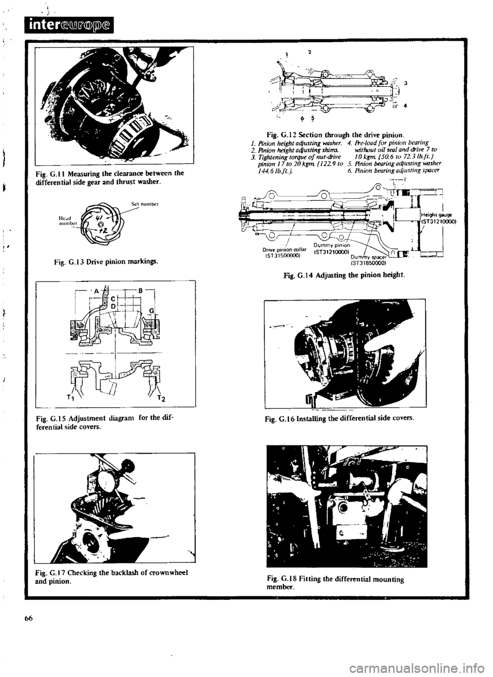
1
Pinion
height
adjusting
kUsher
4
Fte
Ioad
for
pinion
bearing
2
Pinion
height
ad
usting
shims
without
oil
mlI
and
drive
7
to
3
Tightening
torque
of
nut
dril
e
10
kgt1L
5a
6
to
72
3
lb
jl
pinion
17
to
20kg1n
22
9
to
ffnion
bearing
adjusting
w
uher
44
6Ib
ft
J
6
Pillion
bt
flrillgadjusti
lg
s
Jtu
er
fl
i
Ji
l
I
I
J
lJ
i
V
r
IHei
t
giluge
I
lST31210c
0
l
B
I
0
QJ
DUrnmYPinlOn
Drive
pinion
collar
lST3121QOCX
f
1
L
r
IST315000001
Dummvspacer
ST318500001
I
Fig
G
ll
Measuring
the
clearance
between
the
differential
side
gear
and
thrust
washer
Fig
G
t3
Drive
pinion
markings
Fig
G
14
Adjusting
the
pinion
height
1
Fig
G
t
5
Adjustment
diagram
for
the
dif
feren
tiaI
side
covers
Fig
G
16lnstalling
the
differential
side
covers
fig
G
Checking
the
backlash
of
crownwheel
and
pinion
Fig
G
tS
Fining
the
differential
mounting
member
bb
Page 72 of 171
greased
Install
the
flange
washer
and
pinion
nut
Tighten
the
nut
to
a
torque
reading
of
14
17
kgm
101
130
Ib
fL
If
the
cotter
pin
hole
is
not
correctly
aligned
a
suitable
washer
should
be
fitted
Do
NOT
adjust
by
overtightening
the
pinion
nul
Van
Lubricate
the
front
bearing
with
oil
and
place
it
in
the
carrier
Grease
the
lip
of
the
oil
seal
and
install
it
to
the
final
drive
housing
Install
the
drive
pinion
the
new
collapsible
spacer
and
the
drive
flange
Fit
the
drive
pinion
nut
and
tighten
temporarily
until
all
slackness
is
eliminated
from
the
front
and
rear
of
the
drive
pinion
NOTE
Ensure
that
oil
and
grease
have
been
completely
removed
from
the
threads
of
the
pinion
gear
the
pinion
nut
and
the
washer
Tighten
the
pinion
nut
and
check
the
preload
with
a
preload
gauge
As
the
nut
is
tightened
to
the
specified
torque
reading
of
13
20
kgm
94
0
144
6Ib
fL
the
preload
must
be
measured
at
every
five
to
ten
degrees
turn
of
the
pinion
nut
As
the
pinion
nut
is
tightened
the
stepped
portion
of
the
spacer
is
deformed
See
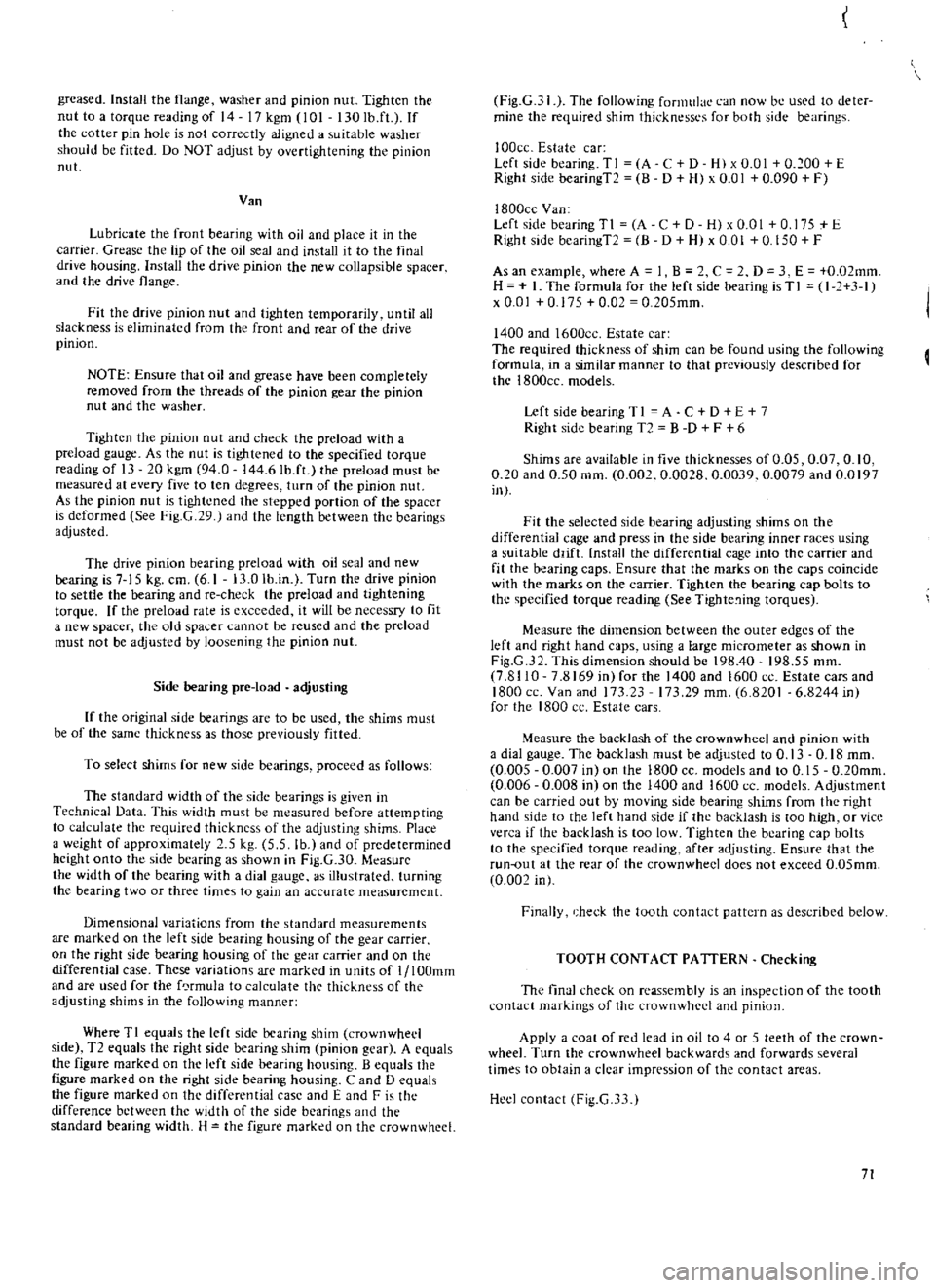
Fig
G
29
J
and
the
length
between
the
bearings
adjusted
The
drive
pinion
bearing
preload
with
oil
seal
and
new
bearing
is
7
15
kg
cm
6
1
13
0
lb
in
Turn
the
drive
pinion
to
settle
the
bearing
and
re
check
the
preload
and
tightening
torque
If
the
preload
rate
is
exceeded
it
will
be
necessry
to
fit
a
new
spacer
the
old
spa
cr
cannot
be
reused
and
the
preload
must
not
be
adjusted
by
loosening
the
pinion
nul
Side
bearing
pre
load
adjusting
If
the
original
side
bearings
arc
to
be
used
the
shims
must
be
of
the
same
thickness
as
those
previously
fitted
To
select
shims
for
new
side
bearings
proceed
as
follows
The
standard
width
of
the
side
bearings
is
given
in
Technical
Data
This
width
must
be
measured
before
attempting
to
calculate
the
required
thickness
of
the
adjusting
shims
Place
a
weight
of
approximately
5
kg
5
5
lb
and
of
predetermined
height
onto
the
side
bearing
as
shown
in
Fig
G
30
Mcasure
the
width
of
the
bearing
with
a
dial
gauge
as
illustrated
turning
the
bearing
two
or
three
times
to
gain
an
accurate
meaSurement
Dimensional
variations
from
the
standard
measurements
are
marked
on
the
left
side
bearing
housing
of
the
gear
carrier
on
the
right
side
bearing
housing
of
the
gear
carrier
and
on
the
differential
case
These
variations
are
marked
in
units
of
l
lOOmm
and
are
used
for
the
f
rmula
to
calculate
t1H
thickness
of
the
adjusting
shims
in
the
following
manner
Where
TI
equals
the
left
side
bearing
shim
crownwhecl
side
T2
equals
the
right
side
bearing
shim
pinion
gear
A
equals
the
figure
marked
on
the
left
side
bearing
housing
B
equals
the
figure
marked
on
the
right
side
bearing
housing
C
and
0
equals
the
figure
marked
on
the
differential
case
and
E
and
F
is
the
difference
bctween
the
width
of
the
side
bearings
and
the
standard
bearing
width
H
the
figure
marked
on
the
crownwhcel
Fig
G
31
The
following
formulae
can
now
be
used
to
deter
mine
the
required
shim
thicknessl
s
for
both
side
bearings
I
OOcc
Estate
car
Left
side
bearing
TI
A
C
D
H
x
0
01
0
100
E
Right
side
bearingT2
B
D
H
x
0
01
0
090
F
I800cc
Van
Left
side
bearingTI
A
C
D
H
xO
OI
0
175
E
Right
side
bcaringT2
8
D
H
x
0
01
0
150
F
As
an
example
where
A
1
B
C
2
D
3
E
0
02mm
H
I
The
formula
for
the
left
side
bearing
is
T
I
I
1
3
1
x
0
01
0
175
0
02
0
205mm
1400
and
1600cc
Estate
car
The
required
thickness
of
shim
can
be
found
using
the
following
formula
in
a
similar
manner
to
that
previously
described
for
the
1800cc
models
Left
side
bearing
T
I
A
C
D
E
7
Right
side
bearing
T2
B
D
F
6
Shims
are
available
in
five
thicknesses
of
0
05
0
07
0
10
0
20
and
0
50
mm
0
002
0
0028
0
0039
0
0079
and
0
0197
in
Fit
the
selected
side
bearing
adjusting
shims
on
the
differential
cage
and
press
in
the
side
bearing
inner
races
using
a
suitable
ddfL
nstall
the
differential
cage
into
the
carrier
and
fit
the
bearing
caps
Ensure
that
the
marks
on
the
caps
coincide
with
the
marks
on
the
carrier
Tighten
the
bearing
cap
bolts
to
the
specified
torque
reading
See
Tighte
ing
torques
Measure
the
dimension
between
the
outer
edges
of
the
left
and
right
hand
caps
using
a
large
micrometer
as
shown
in
Fig
G
32
This
dimension
should
be
198
40
198
55
mm
7
8110
7
8169
in
for
the
1400
and
1600
ce
Estate
cars
and
1800
ce
Van
and
173
23
17329
mm
6
8201
6
8244
inl
for
the
1800
cc
Estate
cars
Measure
the
backlash
of
the
crownwhcel
and
pinion
with
a
dial
gauge
The
backlash
must
be
adjusted
to
0
13
0
18
mm
0
005
0
007
in
on
the
1800
CC
models
and
to
0
15
0
20mm
0
006
0
008
in
on
the
1400
and
1600
cc
models
Adjustment
can
be
carried
out
by
moving
side
bearing
shims
from
the
right
hand
side
to
the
left
hand
side
if
the
backlash
is
too
high
or
vice
verca
if
the
backlash
is
too
low
Tighten
the
bearing
cap
bolts
to
the
specified
torque
reading
after
adjusting
Ensure
that
the
run
out
at
the
rear
of
the
crown
wheel
does
not
exceed
O
05mm
0
002
in
Finally
heck
the
tooth
contact
pattern
as
described
below
TOOTH
CONTACT
PATTERN
Checking
The
final
check
on
reassembly
is
an
inspection
of
the
tooth
contact
markings
of
the
crownwhed
and
pinion
Apply
a
coal
of
red
lead
in
oil
to
4
or
5
teeth
of
the
crown
wheel
Turn
the
crownwheel
backwards
and
forwards
several
times
to
obtain
a
clear
impression
of
the
contact
areas
Heel
contact
Fig
G
3
1
71
Page 105 of 171
inter
f
illl
@
l
l
Au
y
l
ver
I
R
H
I
Equaliler
b2nd
i
b7ke
Pl
te
Iock
band
buk
able
I
I
I
T
@A
Adjuster
cable
oo
pm
Odb
k
SPd
wm
LH
able
C
Note
@
Apply
bearing
grease
@APPIYch
S
i
Pin
fulcrum
hand
brab
lever
6c
1l
Clip
cable
frout
N
nd
brake
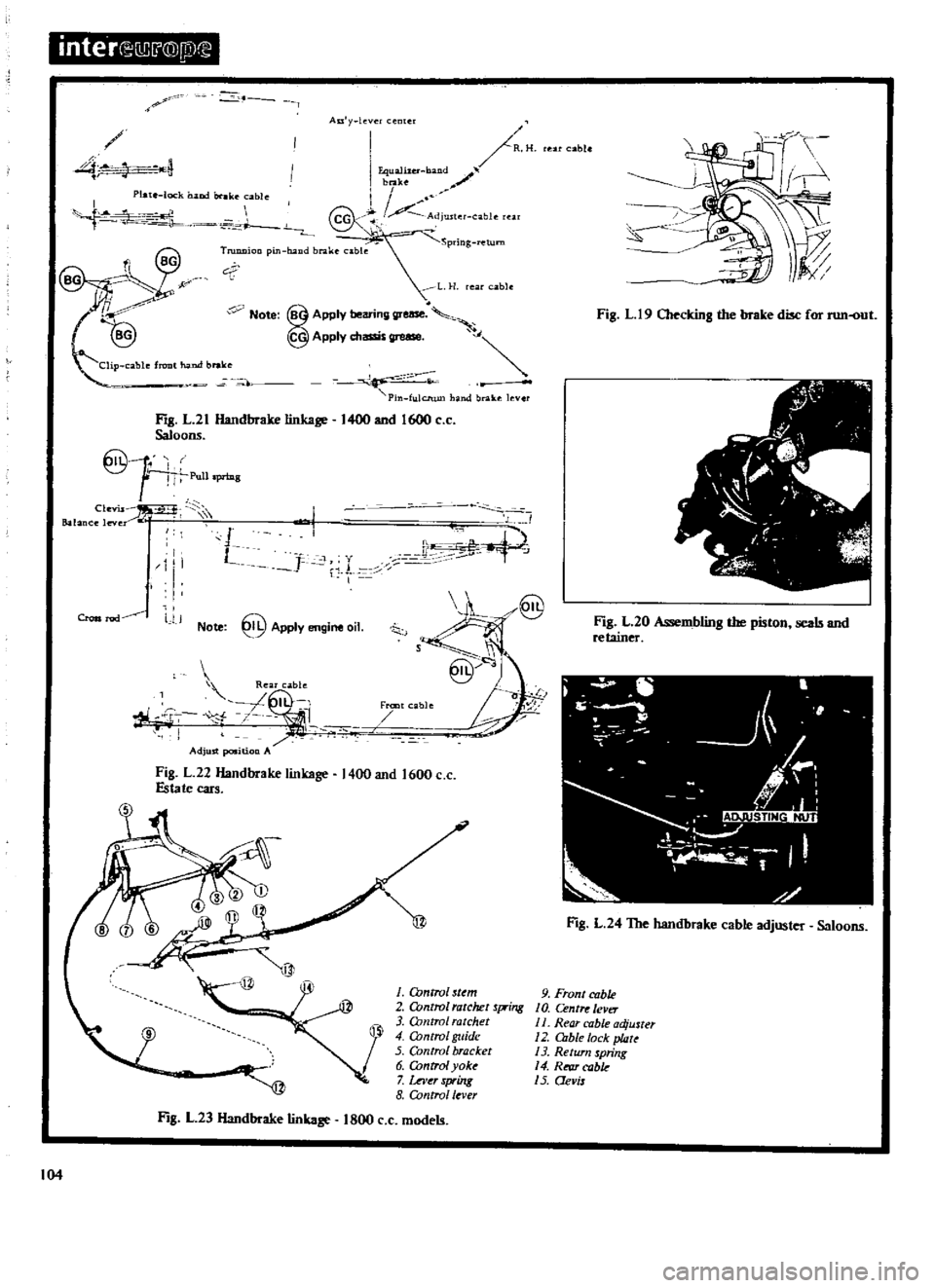
Fill
L21
Handbrake
linkage
1400
and
1600
c
c
Saloons
1
I
J
Pull
priDg
1
Clt
vU
Balance
leve
I
I
J
c
1
1
I
I
1
l
J
L
I
iL
Note
@
Apply
engine
oil
8
S
J
@
I
Aj
Fran
able
Rear
cable
L
I
r
f
7
n
t
i
Adjust
position
A
Fig
L
22
Handbrake
linkage
1400
and
1600
c
c
Estate
cars
1
Control
sUm
2
Control
ratchet
Xing
3
O
mtrol
ratchet
4
O
mtro
guide
5
Control
bracket
6
OJntrol
yoke
7
wer
spring
8
Control
lever
Fig
L
23
Handbrake
linkage
1800
c
c
models
104
able
s
Fig
L
19
Checking
the
brake
disc
for
run
out
1
j
v
fti
r
v
r
Fig
L
20
As
embling
the
piston
seals
and
retainer
ti
J
4
Fill
L
24
The
handbrake
cable
adjuster
Saloons
9
Front
cable
10
Centre
lever
II
Rear
cable
adjuster
12
DIble
lock
plate
13
Return
spring
14
RI
fU
cabk
15
Qevis
Page 111 of 171

inter
r
0J
@
jll@
FIg
M
7
Over
unning
clutch
assembly
1
m
ILE
COMMUTATOR
0
5
to
0
8
mrtl
ROUND
O
0197
to
0
0315
nl
SEGMENT
MICA
CORRECr
INCORRECT
Fig
M
9
Undercutting
the
commutator
insulation
Fig
M
11
Testing
the
field
coils
for
continuity
5
y
SERIES
COIL
5
r
SHUNT
COIL
Fig
M
13
Testing
the
solenoid
witch
10
J
Fig
M
8
Checking
the
brush
pring
tension
Fig
M
lO
Checking
the
armature
shaft
for
run
out
J
I
I
J
I
L
j
J
j
Fig
M
12
Testing
the
field
coils
for
earthing
1
rl
wr
v
E
L
DIMENSION
131
7
to
32
3mm
1
248
to
1
272
in
I
Adjus
llUt
2
PluJlKeradjuster
F
8
M
14
Measuring
the
gap
between
pinion
and
pinion
stop
I