fuse DATSUN 610 1969 Workshop Manual
[x] Cancel search | Manufacturer: DATSUN, Model Year: 1969, Model line: 610, Model: DATSUN 610 1969Pages: 171, PDF Size: 10.63 MB
Page 117 of 171

inter
@IP
Fig
M
33
Removing
the
instrument
panel
h
J
I
II
VI
BATTERY
FUSIBLE
LINK
0
3
Br
WASHER
MOTOR
I
ILR
rj
WIPER
MOTO
R
ILR
lity
111
W
J
9P
l
l
0
0
IGNITION
SWITCH
FUSE
BOX
IDA
0
W
ACC
r
WIPER
SWITCH
P
I
2
W
I
X
9
LWI
t
j
LR
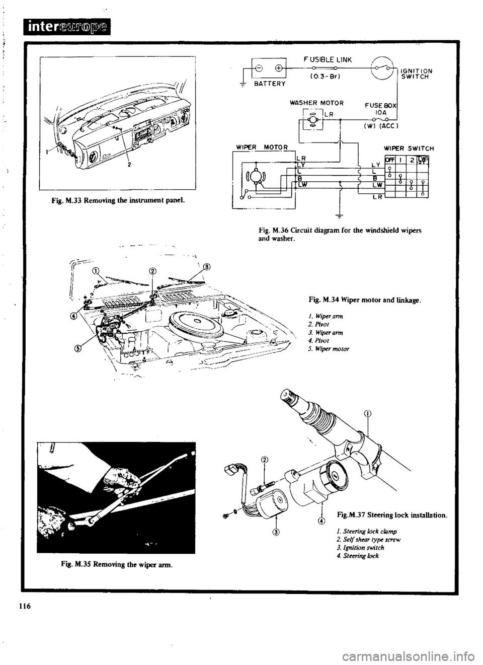
Fig
M
36
Circuit
diagram
for
the
windshield
wipers
and
washer
Fig
M
35
Removing
the
wiper
arm
116
Fig
M
34
Wiper
motor
and
linkage
1
Wiper
arm
2
Pivot
3
Wiper
ann
4
Pirot
5
WiTNr
motor
f
Fig
M
37
Steering
lock
installation
1
Steering
lode
cwmp
2
Self
hear
ty
screw
3
Ignition
switch
4
SUmng
lock
Page 118 of 171

4
Remove
the
shell
covers
from
the
steering
column
slacken
the
screws
securing
the
meter
housing
and
withdraw
the
panel
from
the
facia
Fig
M
33
5
Pull
out
the
12
pole
round
shaped
connector
and
remove
the
speedometer
cable
union
nut
then
remove
the
instru
ment
panel
completely
WINDSCREEN
WIPERS
A
two
speed
wiper
motor
is
fitted
The
motor
has
an
auto
stop
mechanism
and
drives
the
wiper
arms
through
a
link
mechanism
located
behind
the
instrument
panel
If
the
wiper
system
does
not
operate
check
the
fuses
connectors
control
switch
and
motor
If
the
wiper
speed
does
not
change
the
switch
must
be
repaired
or
replaced
If
the
wiper
motor
becomes
unserviceable
it
can
be
removed
from
the
vehicle
in
the
fOllowing
manner
I
Remove
the
connector
plug
from
the
motor
See
Fig
M
34
2
Working
from
the
passenger
compartment
side
of
the
dash
panel
remove
the
nut
connecting
the
wiper
motor
worm
wheel
shaft
to
the
connecting
rod
3
Remove
the
three
bolts
securing
the
wiper
motor
to
the
cowl
and
lift
out
the
motor
Battery
Starter
motor
Type
Output
No
load
Terminal
voltage
Current
Revolution
Load
Terminal
voltage
Current
Torque
Brushes
Brush
length
Wear
limit
Spring
tension
Commutator
Standard
outer
diameter
Wear
limit
Depth
of
nuca
Repair
limit
Repair
accuracy
Qearance
between
armature
shaft
and
bushing
Repair
liinit
Repair
accuracy
Armature
shaft
ou
ter
diameter
Pinion
side
Rear
end
Wear
limit
Bend
limit
The
wiper
arms
can
be
removed
quite
easily
by
taking
off
the
attachment
bolt
as
shown
in
Fig
M
J
5
and
then
pullin
the
wiper
arm
from
the
pivot
shaft
When
installing
the
wiper
arm
make
sure
that
the
blade
is
positioned
approximately
27mm
1
06
in
away
from
the
bottom
of
the
windscreen
and
tighten
the
wiper
arm
attachment
bolt
WINDSCREEN
WASHERS
The
windscreen
washer
SWItch
and
wiper
switch
are
com
bined
in
a
single
unit
See
Fig
M
36
the
washers
can
be
operated
by
turning
the
switch
in
the
appropriate
direction
It
should
be
pointed
out
that
it
is
inadvisable
to
operate
the
washers
for
more
than
30
seconds
at
a
time
If
the
washers
are
operated
in
short
spells
of
approximately
10
seconds
duration
their
working
efficiency
will
remain
unimpaired
for
a
considerable
length
of
time
IGNITION
SWITCH
AND
STEERING
LOCK
The
steering
lock
is
built
in
to
the
goition
switch
When
the
key
is
turned
to
the
LOCK
position
and
then
removed
the
steering
system
is
automatically
locked
by
the
steering
lock
spindle
which
engages
in
a
notch
in
the
collar
on
the
steering
shaft
See
Fig
M
37
The
heads
of
the
screws
are
sheared
off
on
installation
so
that
the
steering
lock
system
cannot
be
tampered
with
If
the
steering
lock
is
to
be
replaced
it
will
be
necessary
to
remove
the
two
securing
screws
8
and
then
drill
out
the
self
shearing
screws
7
When
installing
a
new
steering
lock
tighten
the
new
self
shearing
screws
until
the
heads
shear
TechnICal
Data
12
volt
HITACHI
S114
87M
1
0KW
12
volts
Less
than
60
amperes
More
than
7000
r
p
m
6
3
volts
Less
than
420
amperes
More
than
0
9
mkg
6
5
lb
ft
16
mm
0
630
in
6
5mm
0
256
in
0
8
kg
1
8
lb
33mm
1
299
in
2mm
0
078
in
0
2mm
0
008
in
0
5
0
8mm
0
0197
0
0315
in
0
2mm
0
008
in
0
03
O
lmm
0
0012
0
0039
in
13mm
0
512
in
11
5
mm
0
453
in
O
lmm
0
0039
in
0
08
mm
0
0031
in
Oearance
between
pinion
and
stopper
0
3
1
5mm
0
0118
0
0591
in
ALTERNATOR
Type
HITACHI
LTl25
06
HITACHI
LTl33
05
USA
Canada
More
than
18
amps
at
14
volts
2500
r
p
m
More
than
25
amps
at
14
volts
5000
r
p
m
Output
current
LTl25
06
Output
current
LT
133
05
More
than
24
amps
at
14
volts
2500
r
p
m
More
than
33
amps
at
14
volts
5000
r
p
m
Brushes
Lengtb
Wear
limit
Spring
pressure
14
5mm
0
571
In
7mm
0
2756
in
0
25
0
35
kg
0
55
0
771b
Slip
ring
Outer
diameter
Reduction
limit
Repair
limit
Repair
accuracy
31
mm
1
220
in
I
mm
0
039
in
O
3mm
0
0118
in
0
05
mm
0
0197
in
VOLTAGE
REGULATOR
Type
Regulating
voltage
HITACHI
TL
lZ
37
14
3
15
3
volts
at
200C
680F
117
Page 170 of 171

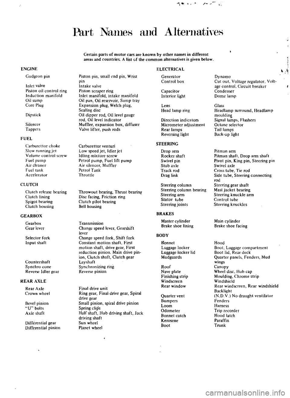
Part
NanleH
and
AlternatlyeS
Certain
parts
of
motor
cars
are
known
by
other
names
in
different
areas
and
countries
A
list
c
f
the
common
alternatives
is
given
below
ENGINE
ELECTRICA
L
Gudgeon
pin
Piston
pin
small
end
pin
Wrist
Generator
Dynamo
pin
Control
box
Cut
out
Voltage
regulator
Volt
Inlet
valve
Intake
valve
age
control
Circuit
breaker
Piston
oil
control
ring
Piston
scraper
ring
Capacitor
Condenser
Induction
manifold
Inlet
manifold
intake
manifold
Interior
light
Dome
lamp
Oil
sump
Oil
pan
Oil
reservoir
Sump
tray
Core
Plug
Expansion
plug
Welch
plug
Lens
Glass
Sealing
disc
Head
lamp
ring
Headlamp
surround
Headlamp
Dipstick
Oil
dipper
rod
Oil
level
gauge
mouldin
rod
Dillevel
indicator
Direction
indicators
Signal
lamps
Flashers
Silencer
Muffler
expansion
box
diffuser
Micrometer
adjustment
Octane
selector
Tappets
Valve
lifter
push
rods
Rear
lamps
Tail
lamps
Reversing
light
Back
u
pUgh
t
FUEL
Carburettor
choke
Carburettor
venturi
STEERING
Slow
running
jet
Low
speed
jet
Idler
jet
Drop
arm
Pitman
ann
Volume
control
screw
Idling
mixture
screw
Rocker
shaft
Pitman
shaft
Drop
ann
shaft
Fuel
pump
Petrol
pump
Fuel
lift
pump
Swivel
pin
Pivot
pin
King
pin
Steering
pin
Air
cleaner
Air
silencer
Muffler
Stub
axle
Swivel
axle
Fuel
lank
Petrol
Tank
Track
rod
Cross
tube
Tie
rod
Accelerator
Throttle
Drag
link
Side
tube
Steering
connecting
rod
CLUTCH
Steering
column
Steering
gear
shaft
Clutch
release
bearing
Throwout
bearing
Thrust
bearing
Steering
column
bearing
Mast
jacket
bearing
Clutch
lining
Disc
facing
Friction
ring
Steering
arm
Steering
knuckle
ann
Spigot
bearing
Clutch
pilot
bearing
Stator
tube
Control
tube
Clutch
housing
Bell
housing
Steering
joints
Steering
knuckles
GEARBOX
BRAKES
Gearbox
Transmission
Master
cylinder
Main
cylinder
Gear
lever
Change
speed
lever
Gearshift
Brake
shoe
lining
Brake
shoe
facing
lever
BODY
Selector
fork
Change
speed
fork
Shift
fork
Input
shaft
Constant
motion
shaft
First
gannet
Hood
motion
shaft
drive
gear
First
Luggage
locker
Boot
Luggage
compartment
reduction
pinion
Main
drive
pin
Luggage
locker
lid
Boot
lid
Rear
deck
ion
Clutch
shaft
Clutch
gear
Mudguards
Quarter
panels
Fenders
Mud
Countershaft
Layshaft
wings
Synchro
cone
Synchronizing
ring
Roof
Canopy
Reverse
Idler
gear
Reverse
pinion
Nave
plate
Wheel
disc
Hub
cap
Finishing
strip
Moulding
Chrome
strip
REAR
AXLE
Windscreen
Windshield
Rear
Axle
Final
drive
unit
Rear
window
Rear
windscreen
Rear
windshield
Crown
wheel
Ring
gear
Final
drive
gear
Spiral
Backlight
drive
gear
Quarter
ven
t
N
D
V
No
draught
ventilator
Bevel
pinion
Small
pinion
spiral
drive
pinion
Bumpers
Fenders
Loom
Harness
U
bolts
Spring
clips
Odometer
Trip
recorder
Axle
shaft
Half
shaft
Hub
driving
shaft
Jack
Bonnet
catch
Hood
latch
driving
shaft
Kerosene
Paraffin
Differential
gear
Sun
wheel
Boot
Trunk
Differential
pinion
Planet
wheel