trunk DATSUN 610 1969 Workshop Manual
[x] Cancel search | Manufacturer: DATSUN, Model Year: 1969, Model line: 610, Model: DATSUN 610 1969Pages: 171, PDF Size: 10.63 MB
Page 76 of 171

Rear
Axle
Rear
SuspensIon
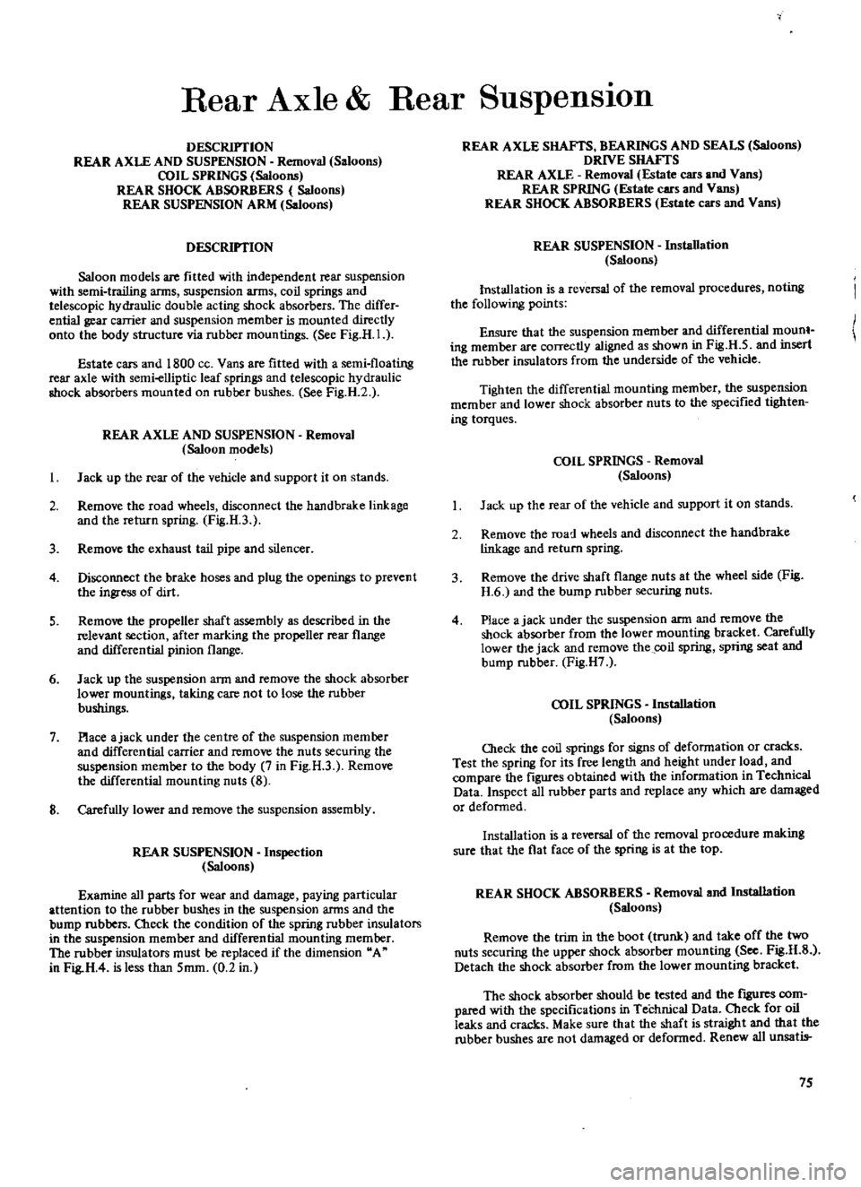
DESCRIPTION
REAR
AXLE
AND
SUSPENSION
Removal
Saloons
COIL
SPRINGS
Saloons
REAR
SHOCK
ABSORBERS
Saloons
REAR
SUSPENSION
ARM
Saloons
DESCRIPTION
Saloon
models
are
fitted
with
independent
rear
suspension
with
semi
trailing
arms
suspension
arms
coil
springs
and
telescopic
hydraulic
double
acting
shock
absorbers
The
differ
ential
gear
carrier
and
suspension
member
is
mounted
directly
onto
the
body
structure
via
rubber
mountings
See
Fig
H
I
Estate
cars
and
1800
ce
Vans
are
fitted
with
a
semi
floating
rear
axle
with
semi
elliptic
leaf
springs
and
telescopic
hydraulic
shock
absorbers
mounted
on
rubrer
bushes
See
Fig
H
2
REAR
AXLE
AND
SUSPENSION
Removal
Saloon
models
I
Jack
up
the
rear
of
the
vehicle
and
support
it
on
stands
2
Remove
the
road
wheels
disconnect
the
hand
brake
linkage
and
the
return
spring
Fig
H
3
3
Remove
the
exhaust
tail
pipe
and
silencer
4
Disconnect
the
brake
hoses
and
plug
the
openings
to
prevent
the
ingress
of
dirt
5
Remove
the
propeller
shaft
assembly
as
described
in
the
relevant
section
after
marking
the
propeller
rear
flange
and
differential
pinion
flange
6
Jack
up
the
suspension
ann
and
remove
the
shock
absorber
lower
mountings
taking
care
not
to
lose
the
rubber
bushings
7
Place
ajack
under
the
centre
of
the
suspension
member
and
differential
carrier
and
remove
the
nuts
securing
the
suspension
member
to
the
body
7
in
Fig
H
3
Remove
the
differential
mounting
nuts
8
8
Carefully
lower
and
remove
the
suspension
assembly
REAR
SUSPENSION
Inspection
Saloons
Examine
all
parts
for
wear
and
damage
paying
particular
attention
to
the
rubber
bushes
in
the
suspension
arms
and
the
bump
rubbers
Check
the
condition
of
the
spring
rubber
insulators
in
the
suspension
member
and
differential
mounting
memrer
The
rubber
insulators
must
be
replaced
if
the
dimension
A
in
Fig
H
4
is
less
than
5mm
0
2
in
REAR
AXLE
SHAFTS
BEARINGS
AND
SEALS
Saloons
DRNE
SHAFTS
REAR
AXLE
Removal
Estate
cars
and
Vans
REAR
SPRING
Estate
cars
and
Vans
REAR
SHOCK
ABSORBERS
Estate
cars
and
Vans
REAR
SUSPENSION
Installation
Saloons
Installation
is
a
reversal
of
the
removal
procedures
noting
the
following
points
Ensure
that
the
suspension
member
and
differential
mount
ing
member
are
correctly
aligned
as
shown
in
Fig
U
5
and
insert
the
rubber
insulators
from
the
underside
of
the
vehicle
Tighten
the
differential
mounting
member
the
suspension
member
and
lower
shock
absorber
nuts
to
the
specified
tighten
ing
torques
COIL
SPRINGS
Removal
Saloons
Jack
up
the
rear
of
the
vehicle
and
support
it
on
stands
2
Remove
the
road
wheels
and
disconnect
the
handbrake
linkage
and
return
spring
3
Remove
the
drive
shaft
flange
nuts
at
the
wheel
side
Fig
H
6
and
the
bump
rubber
securing
nuts
4
Place
ajack
under
the
suspension
ann
and
remove
the
shock
absorber
from
the
lower
mounting
bracket
Carefully
lower
the
jack
and
remove
the
coil
spring
spring
scat
and
bump
rubber
Fig
H7
COIL
SPRINGS
Installation
Saloons
Oleck
the
coil
springs
for
signs
of
deformation
or
cracks
Test
the
spring
for
its
free
length
and
height
under
load
and
compare
the
figures
obtained
with
the
information
in
Technical
Data
Inspect
all
rubber
parts
and
replace
any
which
are
damaged
or
deformed
Installation
is
a
reversal
of
the
removal
procedure
making
sure
that
the
flat
face
of
the
spring
is
at
the
top
REAR
SHOCK
ABSORBERS
Removal
and
Installation
Saloons
Remove
the
trim
in
the
boot
trunk
and
take
off
the
two
nuts
securing
the
upper
shock
absorber
mounting
See
Fig
H
S
Detach
the
shock
absorber
from
the
lower
mounting
bracket
The
shock
absorber
should
be
tested
and
the
fIgUres
com
pared
with
the
specifications
in
Technical
Data
Cbeck
for
oil
leaks
and
cracks
Make
sure
that
the
shaft
is
straight
and
that
the
rubber
bushes
are
not
damaged
or
defonned
Renew
all
unsatis
75
Page 170 of 171

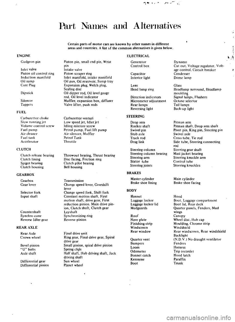
Part
NanleH
and
AlternatlyeS
Certain
parts
of
motor
cars
are
known
by
other
names
in
different
areas
and
countries
A
list
c
f
the
common
alternatives
is
given
below
ENGINE
ELECTRICA
L
Gudgeon
pin
Piston
pin
small
end
pin
Wrist
Generator
Dynamo
pin
Control
box
Cut
out
Voltage
regulator
Volt
Inlet
valve
Intake
valve
age
control
Circuit
breaker
Piston
oil
control
ring
Piston
scraper
ring
Capacitor
Condenser
Induction
manifold
Inlet
manifold
intake
manifold
Interior
light
Dome
lamp
Oil
sump
Oil
pan
Oil
reservoir
Sump
tray
Core
Plug
Expansion
plug
Welch
plug
Lens
Glass
Sealing
disc
Head
lamp
ring
Headlamp
surround
Headlamp
Dipstick
Oil
dipper
rod
Oil
level
gauge
mouldin
rod
Dillevel
indicator
Direction
indicators
Signal
lamps
Flashers
Silencer
Muffler
expansion
box
diffuser
Micrometer
adjustment
Octane
selector
Tappets
Valve
lifter
push
rods
Rear
lamps
Tail
lamps
Reversing
light
Back
u
pUgh
t
FUEL
Carburettor
choke
Carburettor
venturi
STEERING
Slow
running
jet
Low
speed
jet
Idler
jet
Drop
arm
Pitman
ann
Volume
control
screw
Idling
mixture
screw
Rocker
shaft
Pitman
shaft
Drop
ann
shaft
Fuel
pump
Petrol
pump
Fuel
lift
pump
Swivel
pin
Pivot
pin
King
pin
Steering
pin
Air
cleaner
Air
silencer
Muffler
Stub
axle
Swivel
axle
Fuel
lank
Petrol
Tank
Track
rod
Cross
tube
Tie
rod
Accelerator
Throttle
Drag
link
Side
tube
Steering
connecting
rod
CLUTCH
Steering
column
Steering
gear
shaft
Clutch
release
bearing
Throwout
bearing
Thrust
bearing
Steering
column
bearing
Mast
jacket
bearing
Clutch
lining
Disc
facing
Friction
ring
Steering
arm
Steering
knuckle
ann
Spigot
bearing
Clutch
pilot
bearing
Stator
tube
Control
tube
Clutch
housing
Bell
housing
Steering
joints
Steering
knuckles
GEARBOX
BRAKES
Gearbox
Transmission
Master
cylinder
Main
cylinder
Gear
lever
Change
speed
lever
Gearshift
Brake
shoe
lining
Brake
shoe
facing
lever
BODY
Selector
fork
Change
speed
fork
Shift
fork
Input
shaft
Constant
motion
shaft
First
gannet
Hood
motion
shaft
drive
gear
First
Luggage
locker
Boot
Luggage
compartment
reduction
pinion
Main
drive
pin
Luggage
locker
lid
Boot
lid
Rear
deck
ion
Clutch
shaft
Clutch
gear
Mudguards
Quarter
panels
Fenders
Mud
Countershaft
Layshaft
wings
Synchro
cone
Synchronizing
ring
Roof
Canopy
Reverse
Idler
gear
Reverse
pinion
Nave
plate
Wheel
disc
Hub
cap
Finishing
strip
Moulding
Chrome
strip
REAR
AXLE
Windscreen
Windshield
Rear
Axle
Final
drive
unit
Rear
window
Rear
windscreen
Rear
windshield
Crown
wheel
Ring
gear
Final
drive
gear
Spiral
Backlight
drive
gear
Quarter
ven
t
N
D
V
No
draught
ventilator
Bevel
pinion
Small
pinion
spiral
drive
pinion
Bumpers
Fenders
Loom
Harness
U
bolts
Spring
clips
Odometer
Trip
recorder
Axle
shaft
Half
shaft
Hub
driving
shaft
Jack
Bonnet
catch
Hood
latch
driving
shaft
Kerosene
Paraffin
Differential
gear
Sun
wheel
Boot
Trunk
Differential
pinion
Planet
wheel