check oil DATSUN PICK-UP 1977 User Guide
[x] Cancel search | Manufacturer: DATSUN, Model Year: 1977, Model line: PICK-UP, Model: DATSUN PICK-UP 1977Pages: 537, PDF Size: 35.48 MB
Page 41 of 537
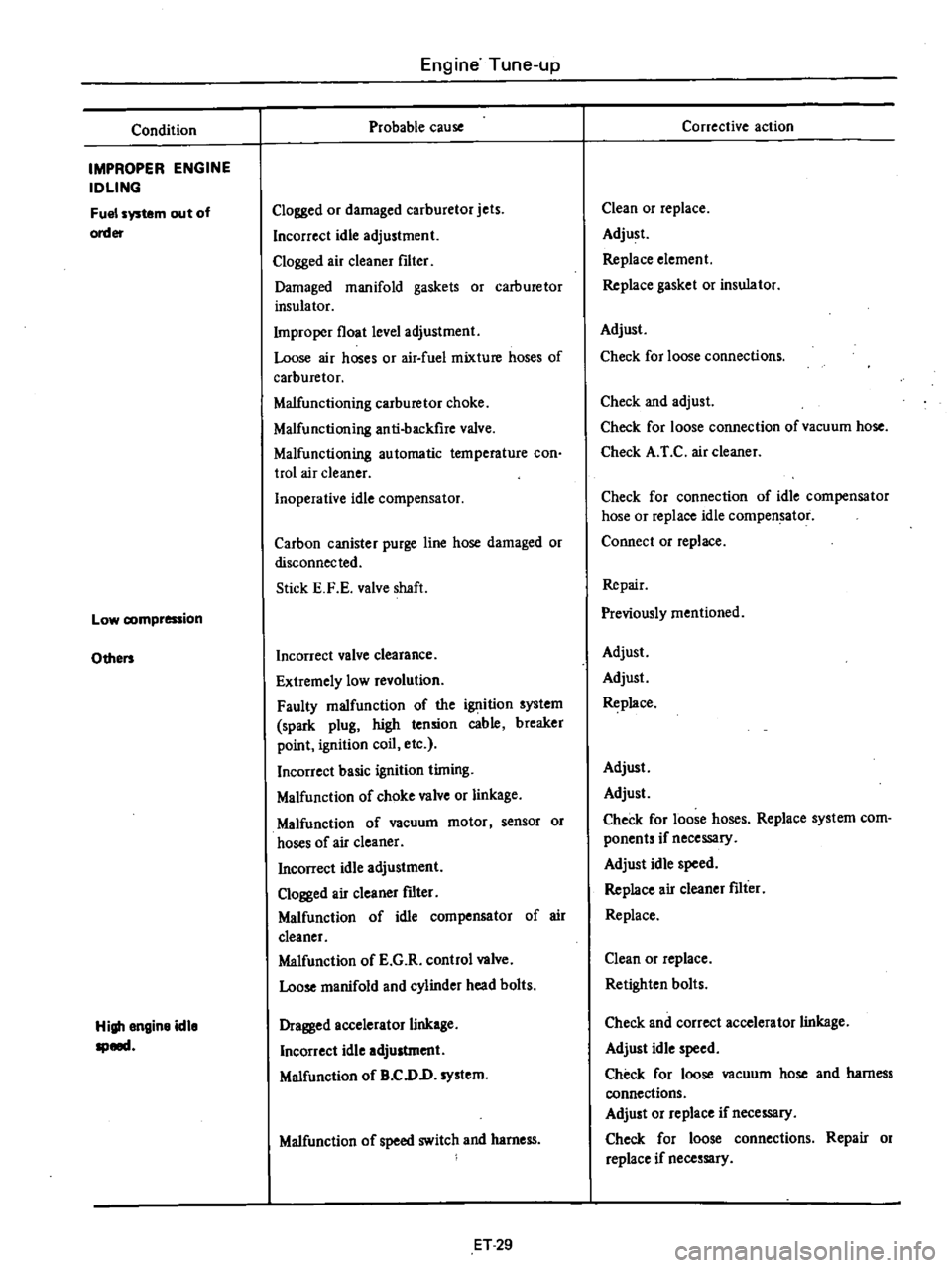
Condition
IMPROPER
ENGINE
IDLING
Fuel
system
out
of
order
Low
compression
Others
High
engine
idle
speed
Engine
Tune
up
Probable
cause
Clogged
or
damaged
carburetor
jets
Incorrect
idle
adjustment
Clogged
air
cleaner
filter
Damaged
manifold
gaskets
or
carburetor
insulator
Improper
float
level
adjustment
Loose
air
hoses
or
air
fuel
mixture
hoses
of
carburetor
Malfunctioning
carburetor
choke
Malfunctioning
anti
backfire
valve
Malfunctioning
automatic
temperature
con
trol
air
cleaner
Inoperative
idle
compensator
Carbon
canister
purge
line
hose
damaged
or
disconnected
Stick
E
F
E
valve
shaft
Incorrect
valve
clearance
Extremely
low
revolution
Faulty
malfunction
of
the
ignition
system
spark
plug
high
tension
cable
breaker
point
ignition
coil
etc
Incorrect
basic
ignition
timing
Malfunction
of
choke
valve
or
linkage
Malfunction
of
vacuum
motor
sensor
or
hoses
of
air
cleaner
Incorrect
idle
adjustment
Clogged
air
cleaner
fdter
Malfunction
of
idle
compensator
of
air
cleaner
Malfunction
of
E
G
R
control
valve
Loose
manifold
and
cylinder
head
bolts
Dragged
accelerator
linkage
Incorrect
idle
adjustment
Malfunction
of
B
CDD
system
Malfunction
of
speed
switch
and
harness
ET
29
Corrective
action
Clean
or
replace
Adjust
Replace
element
Replace
gasket
or
insulator
Adjust
Check
for
loose
connections
Check
and
adjust
Check
for
loose
connection
of
vacuum
hose
Check
A
r
C
air
cleaner
Check
for
connection
of
idle
compensator
hose
or
replace
idle
compen
tor
Connect
or
replace
Repair
Previously
mentioned
Adjust
Adjust
Replace
Adjust
Adjust
Check
for
loose
hoses
Replace
system
com
ponents
if
necessary
Adjust
idle
speed
Replace
air
cleaner
fdter
Replace
Clean
or
replace
Retighten
bolts
Check
and
correct
accelerator
linkage
Adjust
idle
speed
Check
for
loose
vacuum
hose
and
harness
connections
Adjust
or
replace
if
necessary
Check
for
loose
connections
Repair
or
replace
if
necessary
Page 42 of 537
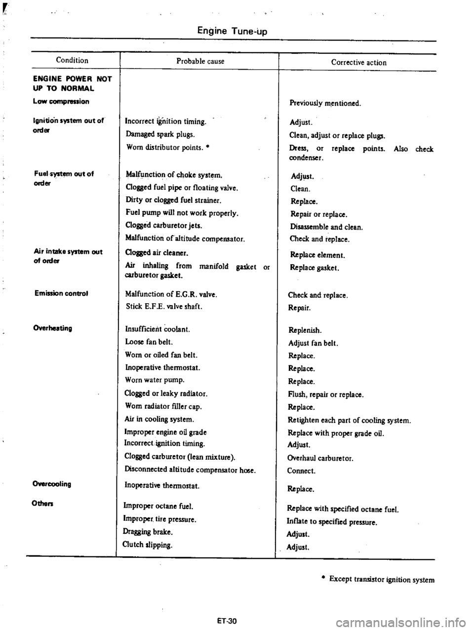
Condition
ENGINE
POWER
NOT
UP
TO
NORMAL
Low
compression
Ignition
system
out
of
order
Fuel
system
out
of
order
Air
intake
system
out
of
order
Emission
control
Overheating
O
cooIing
Others
Engine
Tune
up
Probable
cause
Incorrect
iSnition
timing
Damaged
spark
plugs
Worn
distributor
points
Malfunction
of
choke
system
Clogged
fuel
pipe
or
floating
valve
Dirty
or
clogged
fuel
strainer
Fuel
pump
will
not
work
properly
C10ssed
carburetor
jets
Malfunction
of
altitude
compensator
CIOJBed
air
cleaner
Ail
inhaling
from
manifold
gasket
or
carburetor
gasket
Malfunction
of
E
G
R
valve
Stick
E
F
E
valve
shaft
Insufficient
coolant
Loose
fan
belt
Worn
or
oiled
fan
belt
Inoperative
thermostat
Worn
water
pump
Clogged
or
leaky
radiator
Worn
radiator
filler
cap
Ail
in
cooling
system
Improper
engine
oil
grade
Incorrect
ignition
timing
Clossed
carburetor
lean
mixture
Disconnected
altitude
compensator
hOlle
Inoperative
thermostat
Improper
octane
fuel
L
j
tire
pressure
Dragging
brake
Clutch
slipping
ET
30
Corrective
action
Previously
mentioned
Adjust
Clean
adjust
or
replace
plull
Dress
or
replace
points
Also
check
condenser
Adj
lst
Clean
Replace
Repair
or
replace
Disassemble
and
clean
Check
and
replace
Replace
element
Replace
gasket
Check
and
replace
Repair
Replenish
Adjust
fan
belt
Replace
Replace
Replace
Flush
repair
or
replace
Replace
Retighten
each
part
of
cooling
system
Replace
with
proper
grade
oil
Adjust
Overhaul
carburetor
Connect
Replace
Replace
with
specified
octane
fuel
Inflate
to
specified
pressure
Adjust
Adjust
Except
transistor
ignition
system
Page 43 of 537
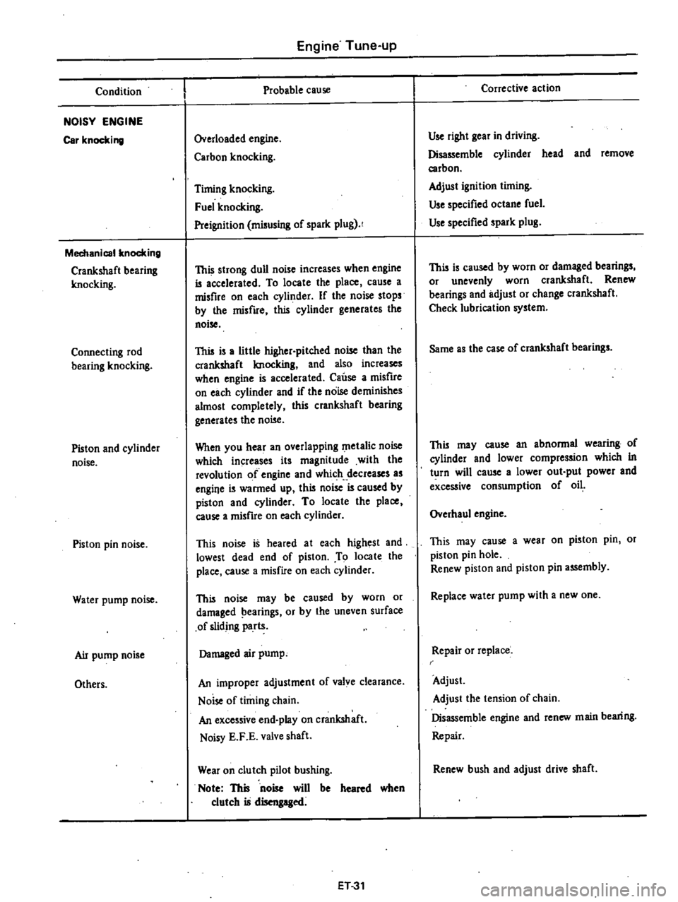
Condition
NOISY
ENGINE
Car
knocking
Mechanical
knocking
Crankshaft
bearing
Imocking
Connecting
rod
bearing
knocking
Piston
and
cylinder
noise
Piston
pin
noise
Water
pump
noise
Air
pump
noise
Others
Engine
Tune
up
Probable
cause
Overloaded
engine
Carbon
knocking
Timing
knocking
Fuel
knocking
Preignition
misusing
of
spark
plug
This
strong
dull
noise
increases
when
engine
is
accelerated
To
locate
the
place
cause
a
misfire
on
each
cylinder
If
the
noise
stops
by
the
misfire
this
cylinder
generates
the
noise
This
is
a
little
higher
pitched
noise
than
the
crankshaft
Imocking
and
also
increases
when
engine
is
accelerated
Cause
a
misfire
on
each
cylinder
and
if
the
noise
deminishes
almost
completely
this
crankshaft
bearing
generates
the
noise
When
you
hear
an
overlapping
metalic
noise
which
increases
its
magnitude
with
the
revolution
of
engine
and
which
decreases
as
engine
is
warmed
up
this
noise
is
caused
by
piston
and
cylinder
To
locate
the
place
cause
a
misfire
on
each
cylinder
This
noise
is
heared
at
each
highest
and
lowest
dead
end
of
piston
To
locate
the
place
cause
a
misfire
on
each
cylinder
This
noise
may
be
caused
by
worn
or
damaged
earings
or
by
the
uneven
surface
of
sliding
parts
Damaged
air
pump
An
improper
adjustment
of
valve
clearance
Noise
of
timing
chain
An
excessive
end
play
on
crankshaft
Noisy
E
F
E
valve
shaft
Wear
on
clutch
pilot
bushing
Note
This
noise
will
be
heared
when
clutch
is
disengaged
ET31
Corrective
action
Use
right
gear
in
driving
Disassemble
cylinder
head
and
remove
carbon
Adjust
ignition
timing
Use
specified
octane
fuel
Use
specified
spark
plug
This
is
caused
by
worn
or
damaged
bearings
or
unevenly
worn
crankshaft
Renew
bearings
and
adjust
or
change
crankshaft
Check
lubrication
system
Same
as
the
case
of
crankshaft
bearings
This
may
cause
an
abnormal
wearing
of
cylinder
and
lower
compression
which
in
turn
will
cause
a
lower
out
put
power
and
excessive
consumption
of
oil
Overhaul
engine
This
may
cause
a
wear
on
piston
pin
or
piston
pin
hole
Renew
piston
and
piston
pin
assembly
Replace
water
pump
with
a
new
one
Repair
or
replace
Adjust
Adjust
the
tension
of
chain
Disassemble
engine
and
renew
main
bearing
Repair
Renew
bush
and
adjust
drive
shaft
Page 44 of 537
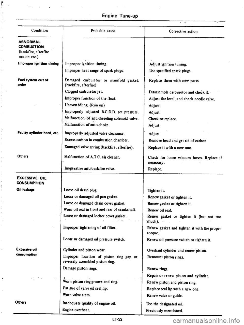
Condition
ABNORMAL
COMBUSTION
backfue
afterflre
run
on
etc
Improper
ignition
timing
Fuel
system
out
of
order
Faulty
cylinder
head
etc
Others
EXCESSIVE
OIL
CONSUMPTION
Oilloak
Excessi
lo
oil
consumption
Others
Engine
Tune
up
probable
cause
Improper
ignition
timing
Improper
heat
range
of
spark
plugs
Damaged
carburetor
or
manifold
gasket
backfue
afterfire
Clol
l
ed
carburetor
jet
Improper
function
of
the
float
Uneven
idling
Run
on
Improperly
adjusted
B
C
D
D
set
pressure
Malfunction
of
anti
dieseling
solenoid
valve
Malfunction
of
auio
choke
Improperly
adjusted
valve
clearance
Excess
carbon
in
combustion
chamber
Damaged
valve
spring
backfire
afterflre
Malfunction
of
A
T
C
air
cleaner
Inoperative
ariti
backfue
valve
Loose
oil
drain
plug
Loose
or
damaged
oil
pan
gasket
Loose
or
damaged
chain
cover
gasket
Worn
oil
seal
in
front
and
rear
of
crankshaft
Loose
or
damaged
locker
cover
gasket
Improper
tightening
of
oil
filter
Loose
or
damaged
oil
pressure
switch
Cylinder
and
pioton
wear
Improper
location
of
piston
ring
gap
or
reversely
assembled
piston
ring
Damage
piston
rings
Worn
piston
ring
groove
and
ring
Fatigue
of
valve
oil
seal
lip
Worn
valve
stem
Inadequate
quality
of
engine
oil
Engine
overheat
ET32
Corrective
action
Adjust
ignition
timing
Use
specified
spark
plugs
Replace
them
with
new
parts
Disassemble
carburetor
and
check
it
Adjust
the
level
and
check
needle
valve
Adjust
Adjust
Check
or
replace
Adjust
Adjust
Remove
head
and
get
rid
of
carbon
Replace
it
with
a
new
one
Check
for
loose
vacuum
hoses
Replace
if
necessary
Replape
Tighten
it
Renew
gasket
or
tighten
it
Renew
gasket
or
tighten
it
Renew
oil
seal
Renew
gasket
or
tighten
it
but
not
too
much
Renew
gasket
and
tighten
it
with
the
proper
torque
Renew
oil
pressure
switch
or
tighten
it
Overhaul
cylinder
and
renew
piston
Remoun
t
piston
rings
Renew
rings
Repair
or
renew
piston
and
cylinder
Renew
piston
and
piston
ring
Replace
seal
lip
with
a
new
one
Renew
valve
or
guide
Use
the
designated
oil
Previously
mentioned
Page 45 of 537

Condition
POOR
FUEL
ECONOMY
Se
the
xplanation
of
the
pow
r
dec
Oth
n
PROBLEM
IN
OTHER
FUNCTIONS
D
cr
d
oil
p
ssure
Excessive
wear
on
the
sliding
parts
Scuffing
of
sliding
parts
Floor
temperature
too
high
California
only
Engine
Tune
up
Probable
cause
Exceeding
idling
revolution
Inoperative
acceleration
recovery
Fuel
leakage
Malfunction
of
B
C
D
D
Malfunction
of
A
r
C
air
cleaner
Inadequate
oil
quality
Overheat
Worn
oil
pump
regulator
valve
Functional
deterioration
of
oil
pump
Blocked
oil
f1lter
Increased
clearance
in
various
sliding
parts
Blocked
oil
strainer
Inoperative
oil
gauge
pressure
switch
Oil
pressure
decreases
Improper
quality
or
contamination
of
oil
Damaged
air
cleaner
Overheat
or
overcoal
Improper
fuel
mixture
Decrease
of
oil
pressure
Insufficient
clearances
Overhea
t
Improper
fuel
mixture
Problem
in
fuel
system
Refer
to
Inspec
tion
of
Fuel
System
Problem
in
ignition
system
Refer
to
In
spection
of
Ignition
System
ET33
Corrective
action
Adjust
it
to
the
designated
rpm
Adjust
it
Repair
or
tighten
the
connection
of
fuel
pipes
Adjust
Check
and
replace
Use
the
designated
oil
Previously
mentioned
Disassemble
oil
pump
and
repair
or
renew
it
Repair
or
replace
it
with
a
new
one
Renew
it
Disassemble
and
replace
the
worn
parts
with
new
ones
Oeanit
Replace
it
with
a
new
one
Previousiy
mentioned
Exchange
the
oil
with
proper
one
and
change
element
Change
elemen
t
Previously
mentioned
Check
the
fuel
system
Previously
mentioned
Readjust
to
the
designated
clearances
Previously
mentioned
Check
the
fuel
system
Check
and
repair
Check
and
repair
Page 49 of 537
r
I
I
PRELIMINARY
CLEANING
AND
INSPECTION
DISASSEMBL
Y
PRELIMINARY
CLEANING
AND
INSt
ECTION
Before
disassembling
engine
note
the
following
I
Fuel
oil
or
water
may
leak
past
cylinder
head
and
block
Prior
to
disassembling
check
cylinder
head
1
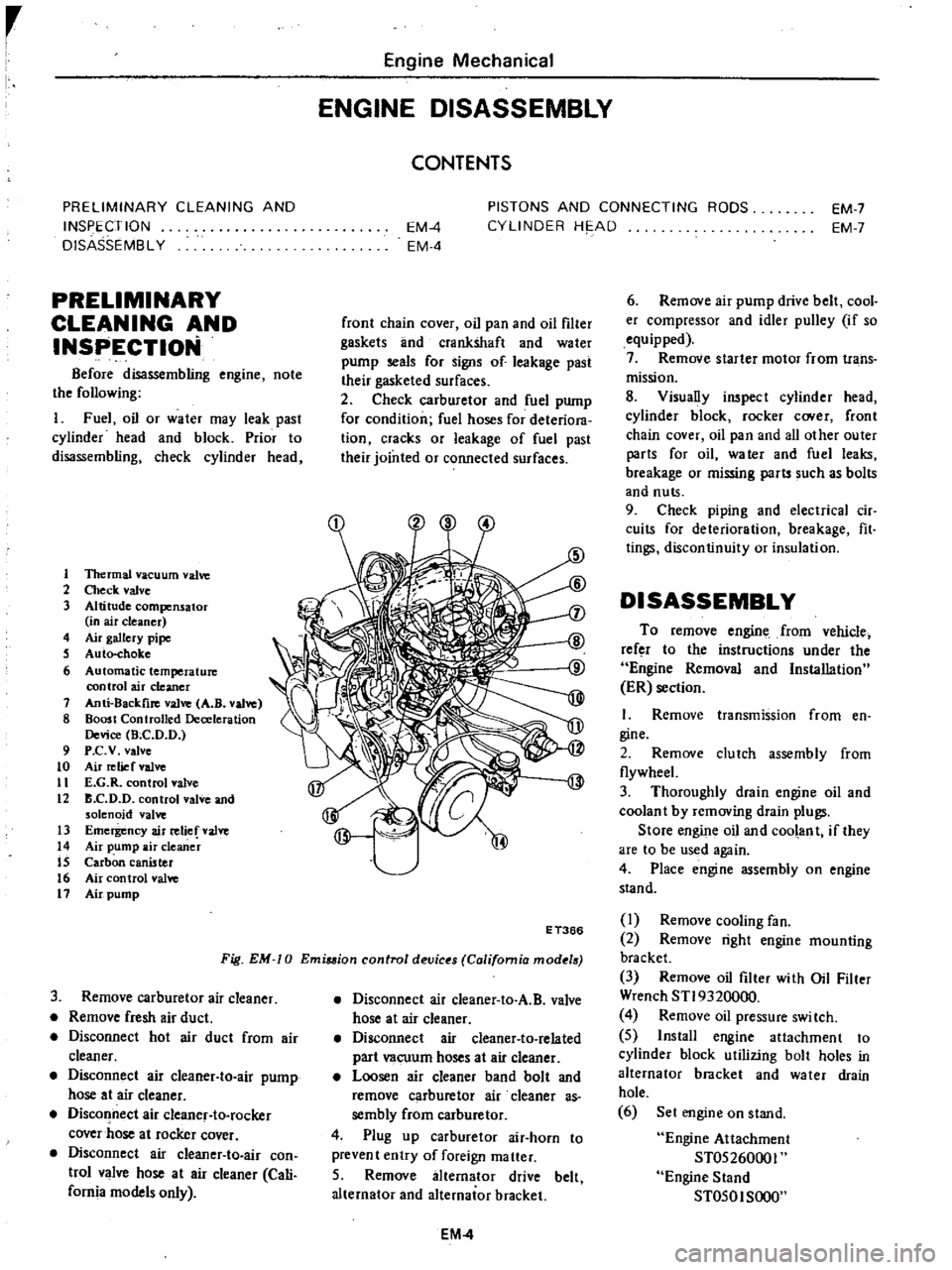
1ltermal
vacuum
valve
2
Check
valve
3
Altitude
compensator
in
air
cleaner
4
Air
gallery
pipe
S
Auto
choke
6
Automatic
temperature
control
air
cleaner
7
Anti
8ackfire
valve
A
B
valve
8
Boost
Controlled
Deceleration
Device
Bee
D
D
9
P
c
v
valve
to
Air
relief
valve
11
E
G
R
control
valve
12
B
C
D
D
control
valve
and
solenoid
valve
13
Emergency
air
relief
valve
14
Air
pump
air
cleaner
IS
Carbon
canister
16
Air
control
valve
11
Air
pump
Engine
Mechanical
ENGINE
DISASSEMBLY
CONTENTS
EM
4
EM
4
PISTONS
AND
CONNECTING
RODS
CYLINDER
HE
AD
EM
7
EM
7
front
chain
cover
oil
pan
and
oil
filter
gaskets
lInd
crankshaft
and
water
pump
seals
for
signs
of
leakage
past
their
gasketed
surfaces
2
Check
carburetor
and
fuel
pump
for
condition
fuel
hoses
for
deteriora
tion
cracks
or
leakage
of
fuel
past
their
jointed
or
connected
surfaces
Fig
EM
0
Emiuion
control
devic
s
California
mod
18
E
T366
3
Remove
carburetor
air
cleaner
Remove
fresh
air
duct
Disconnect
hot
air
duct
from
air
cleaner
Disconnect
air
cleaner
to
air
pump
hose
at
air
cleaner
Disconnect
air
cleanef
to
rocker
cover
hose
at
rocker
cover
Disconnect
air
cIeaner
to
air
con
trol
valve
hose
at
air
cleaner
Cali
fornia
models
only
Disconnect
air
cleaner
to
A
B
valve
hose
at
air
cleaner
Disconnect
air
cleaner
to
related
part
vacuum
hoses
at
air
cleaner
Loosen
air
cleaner
band
bolt
and
remove
carburetor
air
cleaner
as
sembly
from
carburetor
4
Plug
up
carburetor
air
horn
to
prevent
entry
of
foreign
matter
5
Remove
alternator
drive
belt
alternator
and
alternator
bracket
EM
4
6
Remove
air
pump
drive
belt
cool
er
compressor
and
idler
pulley
if
so
equipped
7
Remove
starter
motor
from
trans
mission
8
Visually
inspect
cylinder
head
cylinder
block
rocker
C
Ner
front
chain
cover
oil
pan
and
all
other
outer
parts
for
oil
water
and
fuel
leaks
breakage
or
missing
parts
such
as
bolts
and
nuts
9
Check
piping
and
electrical
cir
cuits
for
deterioration
breakage
fit
tings
discontinuity
or
insulation
DISASSEMBLY
To
remove
engine
from
vehicle
refer
to
the
instructions
under
the
Engine
Removal
and
Installation
ER
section
I
Remove
transmission
from
en
gine
2
Remove
clutch
assembly
from
flywheeL
3
Thoroughly
drain
engine
oil
and
coolan
t
by
removing
drain
plugs
Store
engine
oil
and
coolant
if
they
are
to
be
used
again
4
Place
engine
assembly
on
engine
stand
I
Remove
cooling
fan
2
Remove
right
engine
mounting
bracket
3
Remove
oil
filter
with
Oil
Filter
Wrench
STI9320000
4
Remove
oil
pressure
swi
tch
5
Install
engine
attachment
to
cylinder
block
utilizing
bolt
holes
in
alternator
bracket
and
water
drain
hole
6
Set
engine
on
stand
Engine
Attachment
ST05260001
Engine
Stand
ST050I
SOOO
Page 50 of 537

EM410
Fig
EM
II
Engine
on
engine
land
Remove
oil
level
gauge
6
Remove
carburetor
from
intake
manifold
1
Disconnect
cylinder
block
to
P
C
V
valve
hose
at
P
C
V
valve
2
Disconnect
A
B
valve
to
E
G
R
passage
hose
at
E
G
R
passage
3
Disconnect
vacuum
tube
to
carburetor
hoses
white
and
yellow
at
vacuum
tube
4
Disconnect
fuel
hose
from
carburetor
5
Remove
dash
pot
bracket
from
intake
manifold
6
Remov
carburetor
attaching
bolts
and
remove
carburetor
assembly
and
gasket
7
Disconnect
distributor
high
ten
sion
cables
from
sparkplugs
8
Disconnect
vacuum
hose
from
distributor
and
remove
distributor
as
sembly
9
Disconnect
fuel
hose
from
fuel
pump
and
remove
fuel
and
vacuum
hoses
combined
from
cylinder
head
10
Remove
fuel
pump
assembly
from
cylinder
head
EM412
Fig
EM
12
Removing
fuel
pump
IJ
Remove
in
take
and
exhaust
manifold
assembly
from
cylinder
head
1
Disconnect
vacuum
hose
from
air
control
valve
and
remove
air
con
trol
valve
for
California
and
a
r
hoses
as
an
assembly
Engine
Mechanical
1
Air
control
valve
2
Distributor
EM531
Fig
EM
13
Removing
air
control
valve
Californio
model
2
Remove
carburetor
air
cleaner
bracket
3
Disconnect
vacuum
hose
from
E
G
R
valve
4
Remove
check
valve
from
air
gallery
pipe
5
Disconnect
E
G
R
tube
from
E
G
R
passage
and
exhaust
manifold
6
Remove
E
G
R
passage
and
E
G
R
valve
from
intake
manifold
I
E
G
R
passage
2
E
G
R
tube
Fig
EM
14
EM532
Removing
E
G
R
tube
and
passage
7
Remove
F
l
C
D
bracket
from
cylinder
head
if
so
equipped
8
Disconnect
vacuum
hoses
from
thermal
vacuum
valve
and
remove
thermostat
housing
and
gasket
from
cylinder
head
EM089
Fig
EM
15
Removing
thermostat
housing
EM
5
9
Remove
cylinder
block
to
P
C
V
valve
hose
blow
by
gas
hose
from
cylinder
block
10
Remove
manifold
attaching
bolts
and
remove
intake
and
exhaust
manifold
assembly
and
gasket
from
cylinder
head
Fig
EM
16
Removing
intake
and
exhaust
manifold
assembly
11
Remove
intake
and
exhaust
manifold
attaching
bolts
and
separate
intake
manifold
from
exhaust
mani
fold
12
Remove
air
gallery
pipes
from
exhaust
manifold
12
Remove
left
engi
e
mounting
bra
et
from
cylinder
blopk
13
Remove
air
pump
and
cooler
compressor
bracket
14
Remove
crankshaft
pulley
in
stalling
bolt
and
washer
and
then
remove
pulley
with
a
two
jaw
puller
15
Remove
water
pump
assembly
16
Remove
rocker
cover
17
R
emove
spark
plugs
18
Remove
fuel
pump
drive
earn
19
Remove
camshaft
sprocket
Refer
to
the
following
note
during
operation
when
removing
camshaft
sprocket
from
engine
installed
on
car
EM091
Fig
EM
17
Removing
cammaf
sprocket
Page 53 of 537
r
Engine
Mechanical
INSPECTION
AND
REPAIR
PREPARATION
FOR
INSPECTION
CYLINDER
HEAD
AND
VALVE
CHECKING
CYLINDER
HEAD
MATING
FACE
VALVE
ASSEMBLY
VALVE
SPRING
ROCKER
ARM
AND
VALVE
ROCKER
PIVOT
VALVE
GUIDE
VALVE
SEAT
INSERTS
CAMSHAFT
AND
CAMSHAFT
BEARING
CAMSHAFT
BEARING
CLEARANCE
VALVE
TIMING
CAMSHAFT
ALIGNMENT
CYLINDER
BLOCK
HOW
TO
MEASURE
CYLINDER
BORE
CYLINDER
BORING
PREPARATION
FOR
INSPECTI
N
I
Before
cleaning
check
for
signs
of
water
and
oil
leaks
in
cylinder
block
and
head
2
Clean
oil
carbon
deposits
and
sealant
from
an
parts
Remove
gasket
3
Clean
all
oil
holes
with
solvent
and
dry
with
compressed
air
Make
sure
that
they
are
not
restricted
CYLINDER
HEAD
AND
VALVE
CHECKING
CYLINDER
HEAD
MATING
FACE
EM407
Fig
EM
34
Cylinder
head
CONTENTS
EM
8
EM
B
EM
8
EM
8
EM
9
EM
lO
EM
l0
EM
11
EM
12
EM
12
EM
12
EM
13
EM
13
EM
13
EM
14
PISTONS
PISTON
PINS
AND
PISTON
RINGS
CONNECTING
ROD
CRANKSHAFT
BUSHING
AND
BEARING
MEASUREMENT
OF
MAIN
BEARING
CLEARANCE
MEASUREMENT
OF
CONNECTING
ROD
BEARING
CLEARANCE
FITTING
BEARINGS
MISCELLANEOUS
COMPONENTS
CRANKSHAFT
AND
CAMSHAFT
SPROCKETS
CHAIN
TENSIONER
AND
CHAIN
GUIDE
FLYWHEEL
FRONT
COVER
AND
REAR
OIL
SEAL
Note
Never
remove
camshaft
bear
ings
unless
you
have
a
Suitable
machine
or
boring
Camshaft
bear
ing
in
line
If
you
once
remove
camshaft
bearings
bearing
centers
will
come
out
o
alignment
reo
conditioning
is
very
difficult
with
out
center
borings
L
Make
a
v
isual
check
for
cracks
and
flaws
2
Measure
the
surface
of
cylinder
head
on
cylinder
block
side
for
warpage
If
it
is
found
to
be
beyond
the
limit
designated
below
regrind
the
affected
surface
with
a
surface
grinder
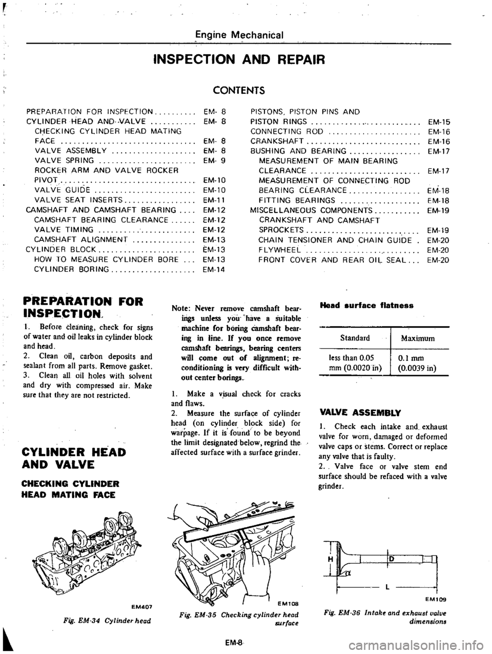
Fig
EM
35
Checking
cylinder
head
8JJrface
EM
8
Head
surface
flatnes
Standard
less
than
0
05
mm
0
0020
in
O
lmm
0
0039
in
EM
15
EM
16
EM
16
EM
17
EM
17
EM
1B
EM
18
EM
19
EM
19
EM
20
EM
20
EM
20
Maximum
VALVE
ASSEMBLY
Check
each
intake
and
exhaust
valve
for
worn
damaged
or
deformed
valve
caps
or
stems
Correct
or
replace
any
valve
that
is
faulty
2
Valve
face
or
valve
stem
end
surface
should
be
refaced
with
a
valve
grinder
10
L
I
I
I
EM109
Fig
EM
36
Intak
and
exhaust
valve
dimensions
Page 57 of 537
Intake
Engine
Mechanical
I
600
38
1
496I
dia
W
39
6
I
559Ildia
1
8
1
6457
dia
45
1
71l1
Unit
mm
in
Exhaust
30
30
1
l811
di
I
32
6
2835
dia
34
6
1
3622
dia
137
1
4567
dia
Unit
mm
m
CAMSHAFT
AND
CAMSHAFT
BEARING
CAMSHAnBEARING
CLEARANCE
Measure
inside
diameter
of
earn
haft
beating
with
an
inside
dial
gauge
and
outside
diameter
of
camshaft
jour
nal
with
a
micrometer
If
wear
is
found
inside
of
bracket
replace
cyl
inder
head
assembly
EM121
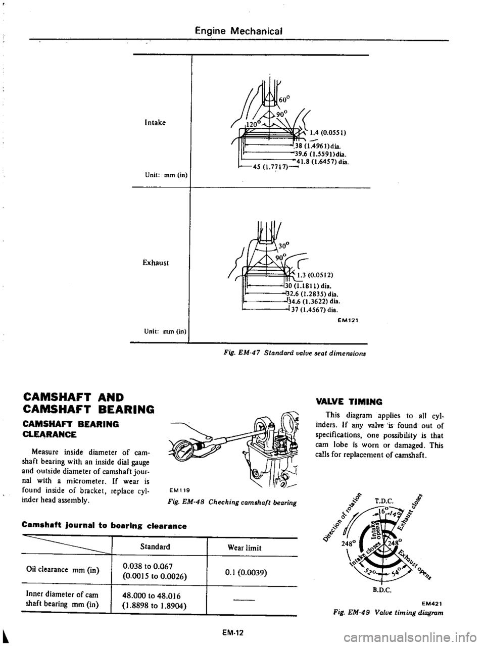
Fig
EM
47
Standard
value
aeat
dimensions
EM119
Fig
EM
48
Checking
cam
haft
bearing
Camshaft
journal
to
bearing
clearance
Standard
Wear
limit
Oil
clearance
mm
in
0
038
to
0
067
0
0015
to
0
0026
0
1
0
0039
Inner
diameter
of
earn
shaft
bearing
mm
in
48
000
to
48
016
1
8898
to
1
8904
EM
12
VALVE
TIMING
This
diagram
applies
to
all
cyl
inders
If
any
valve
is
found
out
of
specifications
one
possibility
that
carn
lobe
is
worn
or
damaged
This
calls
for
replacement
of
camshaft
B
D
C
EM421
Fig
EM
49
Value
timing
diagram
Page 60 of 537

Engine
Mechanical
Notes
a
When
measuring
clearance
slowly
pull
feeier
gaUge
siraight
upward
b
It
Is
reConUnended
that
piston
and
cylinder
be
hel
ted
to
200C
680F
PISTONS
PISTON
PINS
AND
PISTON
RINGS
I
Remove
carbon
from
piston
and
ring
grooves
with
a
ca
bon
scraper
and
a
curved
steel
wire
Clean
out
oil
slots
in
bottom
land
of
oil
ring
groove
2
Check
for
damage
scratches
and
wear
Replace
if
necessary
3
Meas1
1re
side
clearance
of
rings
in
ring
grooves
as
each
ring
is
installed
Side
clearance
should
be
as
follows
00
I
EM542
Fig
EM
58
Measuring
ring
gap
Notes
a
When
piston
ring
only
is
to
be
replaced
without
cylinder
bore
being
corrected
measure
gap
at
bottom
of
cylinder
where
wear
is
minor
b
Oversize
piston
rings
are
available
for
serv
ce
Oversize
0
5
mm
0
0197
in
and
1
0
mm
0
0394
in
5
Measure
piston
pin
hole
in
rela
tion
to
outer
diameter
of
pin
If
wear
exceeds
limit
replace
each
piston
pin
together
with
the
piston
on
which
it
is
installed
6
Determine
the
fitting
of
piston
pin
into
piston
pin
hole
to
such
an
extent
that
it
can
be
finger
pressed
at
room
temperature
This
piston
pin
must
be
a
tight
pre
s
fit
into
connect
ing
rod
t
J
f
rr
11
1
I
EM541
Fig
EM
56
Measuring
piaton
fit
in
cylinder
Fig
EM
57
Measuring
piston
ring
side
clearance
Side
clearance
Unit
mm
in
I
Second
ring
I
I
Wear
limit
Standard
0
040
to
0
073
0
0016
to
0
0029
0
030
to
0
070
I
0
0012
to
0
0028
I
Top
ring
0
1
0
0039
Oil
ring
f
feeler
gauge
Ring
should
be
placed
to
diameter
at
upper
or
lower
limit
of
ring
travel
4
Push
ring
into
cylinder
with
pis
ton
so
as
to
place
it
squarely
in
cylinder
measure
ring
gap
with
a
EM131
Ring
gap
Fig
EM
59
Piston
pin
fitting
Unit
rom
in
Standard
Wear
limit
0
25
to
0
40
0
0098
to
0
0157
0
30
to
0
50
0
0
II
8
to
0
0197
Top
ring
Second
ring
1
0
0
0394
EM132
0
30
to
0
90
0
0118
to
0
0354
Oil
ring
Fig
EM
60
Measuring
pi
ton
pin
diamet
EM
15