wheel DODGE AVENGER 2013 2.G Owner's Manual
[x] Cancel search | Manufacturer: DODGE, Model Year: 2013, Model line: AVENGER, Model: DODGE AVENGER 2013 2.GPages: 108, PDF Size: 3.35 MB
Page 77 of 108
JACKING AND TIRE CHANGING
Jack Location
• The jack and jack-handle are stowed under the load floor in the trunk.
Spare Tire Stowage
• The compact spare tire is stowed under the rear load floor in the trunk.
Spare Tire Removal
• Lift up the load floor cover and remove the hold down.
Preparations For Jacking
1. Park the vehicle on a firm, level surface.Avoid ice or slippery areas.
2. Turn on the Hazard Warning flashers.
3. Set the parking brake.
4.
Place the shift lever into PARK (automatic
transmission) or REVERSE (manual trans-
mission).
5. Turn OFF the ignition.
6. Block both the front and rear of the wheel diagonally opposite the jacking position. For example, if changing the right front tire, block the left rear wheel.
NOTE:
Passengers should not remain in the vehicle
while the vehicle is being jacked.
WHAT TO DO IN EMERGENCIES
75
Page 78 of 108
Jacking Instructions
1. Remove the scissors jack and lug wrenchfrom the spare wheel as an assembly.
Turn the jack screw to the left to loosen
the lug wrench, and remove the wrench
from the jack assembly.
NOTE:
The jack handle attaches to the side of the
jack with two attachment points. When the
jack is partially expanded, the tension be-
tween the two attachment points holds the
jack handle in place.
2. Loosen, but do not remove, the wheel nuts by turning them to the left one turn
while the wheel is still on the ground.
3. There is a front and rear jacking location on each side of the vehicle.
WHAT TO DO IN EMERGENCIES
76
Page 79 of 108
4. Turn the jack screw to the left until thejack can be placed under the jacking lo-
cation. Once the jack is positioned, turn
the jack screw to the right until the jack
head is properly engaged with the lift area
closest to the wheel to be changed. Do
not raise the vehicle until you are sure the
jack is securely engaged.
5. Raise the vehicle by turning the jack screw to the right, using the swivel
wrench. Raise the vehicle only until the
tire just clears the surface and enough
clearance is obtained to install the spare
tire. Minimum tire lift provides maximum
stability.
6. Remove the wheel nuts, and pull the wheel and wheel covers (where applicable) off the hub. Install the spare wheel and wheel nuts with the cone shaped end of the nuts toward
the wheel. Lightly tighten the nuts.
7. Lower the vehicle by turning the jack screw to the left.
8. Finish tightening the nuts. Push down on the wrench while at the end of the handle
for increased leverage. Tighten the lug
nuts in a star pattern until each nut has
been tightened twice. The correct wheel
nut torque is 100 ft lbs (135 N·m). If you
doubt that you have tightened the nuts
correctly, have them checked with a
torque wrench by your authorized dealer
or at a service station.
9. Remove the wheel blocks and lower the jack until it is free. Reassemble the lug wrench to the jack assembly and stow it in the spare tire area. Secure the assembly using the
means provided.
10. Place the deflated (flat) tire in the cargo area and have the tire repaired or replaced as
soon as possible.
11. Check the tire pressure as soon as possible. Correct the tire pressure as required.
WHAT TO DO IN EMERGENCIES
77
Page 80 of 108
Road Tire Installation
Vehicles Equipped With Wheel Covers
1. Mount the road tire on the axle.
2. To ease the installation process for steel wheels with wheel covers, install two lug nutson the mounting studs which are on each side of the valve stem. Install the lug nuts with
the cone shaped end of the nut toward the wheel. Lightly tighten the lug nuts.
3.
Align the valve notch in the wheel cover
with the valve stem on the wheel. Install
the cover by hand, snapping the cover over
the two lug nuts. Do not use a hammer or
excessive force to install the cover.
4. Install the remaining lug nuts with the cone shaped end of the nut toward the
wheel. Lightly tighten the lug nuts.
5. Lower the vehicle to the ground by turn- ing the jack handle counterclockwise.
6. Finish tightening the lug nuts. Push down on the wrench while at the end of the
handle for increased leverage. Tighten
the lug nuts in a star pattern until each
nut has been tightened twice. The correct
tightness of each lug nut is 100 ft/lbs (135 N·m). If in doubt about the correct tightness,
have them checked with a torque wrench by your authorized dealer or service station.
7. After 25 miles (40 km) check the lug nut torque with a torque wrench to ensure that all lug nuts are properly seated against the wheel.
Vehicles Without Wheel Covers
1. Mount the road tire on the axle.
2. Install the remaining lug nuts with the cone shaped end of the nut toward the wheel. Lightly tighten the lug nuts.
3. Lower the vehicle to the ground by turning the jack handle counterclockwise.
4. Finish tightening the lug nuts. Push down on the wrench while at the end of the handle for increased leverage. Tighten the lug nuts in a star pattern until each nut has been
tightened twice. The correct tightness of each lug nut is 100 ft/lbs (135 N·m). If in doubt
about the correct tightness, have them checked with a torque wrench by your authorized
dealer or service station.
5. After 25 miles (40 km) check the lug nut torque with a torque wrench to ensure that all lug nuts are properly seated against the wheel.
1 — Valve Stem 4 — Wheel Cover
2 — Valve Notch 5 — Mounting Stud
3 — Wheel Lug Nut
WHAT TO DO IN EMERGENCIES
78
Page 81 of 108
CAUTION!
•Do not attempt to raise the vehicle by jacking on locations other than those indicated
in the Jacking Instructions for this vehicle.
• Be sure to mount the spare tire with the valve stem facing outward. The vehicle could be damaged if the spare tire is mounted incorrectly.
WARNING!
• Being under a jacked-up vehicle is dangerous. The vehicle could slip off the jack and
fall on you. You could be crushed. Never put any part of your body under a vehicle that
is on a jack. If you need to get under a raised vehicle, take it to a service center where
it can be raised on a lift.
• Never start or run the engine while the vehicle is on a jack.
• The jack is designed to be used as a tool for changing tires only. The jack should not
be used to lift the vehicle for service purposes. The vehicle should be jacked on a firm
level surface only. Avoid ice or slippery areas.
• Do not attempt to change a tire on the side of the vehicle close to moving traffic, pull
far enough off the road to avoid the danger of being hit when operating the jack or
changing the wheel.
•
Carefully follow these tire changing warnings to help prevent personal injury or damage
to your vehicle:
• Always park on a firm, level surface as far from the edge of the roadway as pos-
sible before raising the vehicle.
• Turn on the Hazard Warning flasher.
• Block the wheel diagonally opposite the wheel to be raised.
• Set the parking brake firmly and set an automatic transmission in PARK; a
manual transmission in REVERSE.
• Do not let anyone sit in the vehicle when it is on a jack.
• Do not get under the vehicle when it is on a jack.
•
Only use the jack in the positions indicated and for lifting this vehicle during a tire change.
• If working on or near a roadway, be extremely careful of motor traffic.
•
To assure that spare tires, flat or inflated, are securely stowed, spares must be stowed
with the valve stem facing the ground.
•Raising the vehicle higher than necessary can make the vehicle less stable. It could slip
off the jack and hurt someone near it. Raise the vehicle only enough to remove the tire.
• To avoid possible personal injury, handle the wheel covers with care to avoid contact
with any sharp edges.
•
A loose tire or jack thrown forward in a collision or hard stop could injure the occupants
in the vehicle. Have the deflated (flat) tire repaired or replaced immediately.
• To avoid the risk of forcing the vehicle off the jack, do not tighten the lug nuts fully
until the vehicle is lowered to the ground. Failure to follow this warning may result in
personal injury.
WHAT TO DO IN EMERGENCIES
79
Page 82 of 108
BATTERY LOCATION
• The battery in your vehicle is located between the left front headlight assembly and theleft front wheel splash shield. To allow jump-starting there are remote battery posts
located on the left side of the engine compartment.
JUMP-STARTING
• If your vehicle has a discharged battery it can be jump-started using a set of jumpercables and a battery in another vehicle or by using a portable battery booster pack.
Jump-starting can be dangerous if done improperly so please follow the procedures in
this section carefully.
NOTE:
When using a portable battery booster pack follow the manufacturer's operating instruc-
tions and precautions.
Preparations For Jump-Start
• The battery in your vehicle is located between the left front headlight assembly
and the left front wheel splash shield.
To allow jump-starting there are remote
battery posts located on the left side of
the engine compartment.
1. Set the parking brake, shift the automatic transmission into PARK and turn the igni-
tion to LOCK.
2. Turn off the heater, radio, and all unnec- essary electrical accessories.
3. Remove the protective cover over the re- mote positive (+)battery post. To remove
the cover, press the locking tab and pull
upward on the cover.
WHAT TO DO IN EMERGENCIES
80
Page 85 of 108
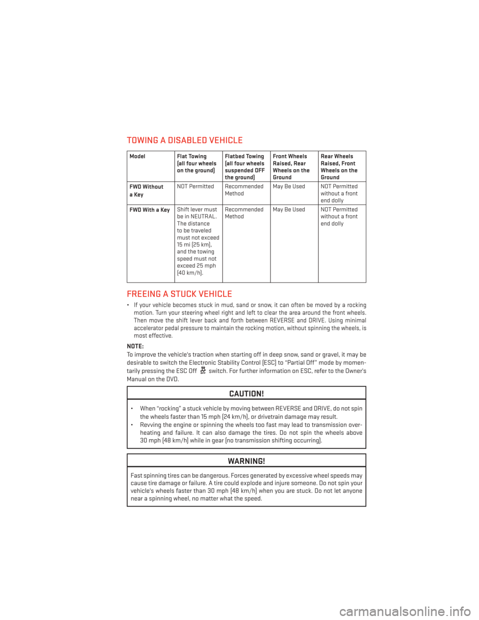
TOWING A DISABLED VEHICLE
ModelFlat Towing
(all four wheels
on the ground) Flatbed Towing
(all four wheels
suspended OFF
the ground)Front Wheels
Raised, Rear
Wheels on the
GroundRear Wheels
Raised, Front
Wheels on the
Ground
FWD Without
aKey NOT Permitted Recommended
MethodMay Be Used NOT Permitted
without a front
end dolly
FWDWithaKey Shift lever must
be in NEUTRAL.
The distance
to be traveled
must not exceed
15 mi (25 km),
and the towing
speed must not
exceed 25 mph
(40 km/h). Recommended
Method
May Be Used NOT Permitted
without a front
end dolly
FREEING A STUCK VEHICLE
•If your vehicle becomes stuck in mud, sand or snow, it can often be moved by a rocking
motion. Turn your steering wheel right and left to clear the area around the front wheels.
Then move the shift lever back and forth between REVERSE and DRIVE. Using minimal
accelerator pedal pressure to maintain the rocking motion, without spinning the wheels, is
most effective.
NOTE:
To improve the vehicle's traction when starting off in deep snow, sand or gravel, it may be
desirable to switch the Electronic Stability Control (ESC) to “Partial Off” mode by momen-
tarily pressing the ESC Off
switch. For further information on ESC, refer to the Owner's
Manual on the DVD.
CAUTION!
• When “rocking” a stuck vehicle by moving between REVERSE and DRIVE, do not spin the wheels faster than 15 mph (24 km/h), or drivetrain damage may result.
• Revving the engine or spinning the wheels too fast may lead to transmission over- heating and failure. It can also damage the tires. Do not spin the wheels above
30 mph (48 km/h) while in gear (no transmission shifting occurring).
WARNING!
Fast spinning tires can be dangerous. Forces generated by excessive wheel speeds may
cause tire damage or failure. A tire could explode and injure someone. Do not spin your
vehicle's wheels faster than 30 mph (48 km/h) when you are stuck. Do not let anyone
near a spinning wheel, no matter what the speed.
WHAT TO DO IN EMERGENCIES
83
Page 98 of 108
TIRE PRESSURES
• Check the inflation pressure of each tire, including the spare tire, at least monthly andinflate to the recommended pressure for your vehicle.
• The tire pressures recommended for your vehicle are found on the “Tire and Loading Information” label located on the driver’s side door opening.
NOTE:
Refer to the Owner's Manual on the DVD for
more information regarding tire warnings
and instructions.
WARNING!
• Overloading of your tires is dangerous. Overloading can cause tire failure, affect vehicle handling, and increase your stopping distance. Use tires of the recom-
mended load capacity for your vehicle. Never overload them.
• Improperly inflated tires are dangerous and can cause collisions. Under-inflation is the leading cause of tire failure and may result in severe cracking, component
separation, or “blow out”. Over-inflation reduces a tire’s ability to cushion shock.
Objects on the road and chuck holes can cause damage that results in tire failure.
Unequal tire pressures can cause steering problems. You could lose control of your
vehicle. Over-inflated or under-inflated tires can affect vehicle handling and can fail
suddenly, resulting in loss of vehicle control.
WHEEL AND WHEEL TRIM CARE
• All wheels and wheel trim, especially aluminum and chrome plated wheels, should be
cleaned regularly with a mild soap and water to prevent corrosion.
• To remove heavy soil and/or excessive brake dust, use MOPAR® Wheel Cleaner or equivalent or select a non-abrasive, non-acidic cleaner.
CAUTION!
Do not use scouring pads, steel wool, a bristle brush, or metal polishes. Do not use oven
cleaner. These products may damage the wheel's protective finish. Avoid automatic car
washes that use acidic solutions or harsh brushes that may damage the wheel's protec-
tive finish. Only MOPAR® Wheel Cleaner or equivalent is recommended.
MAINTAINING YOUR VEHICLE
96
Page 102 of 108
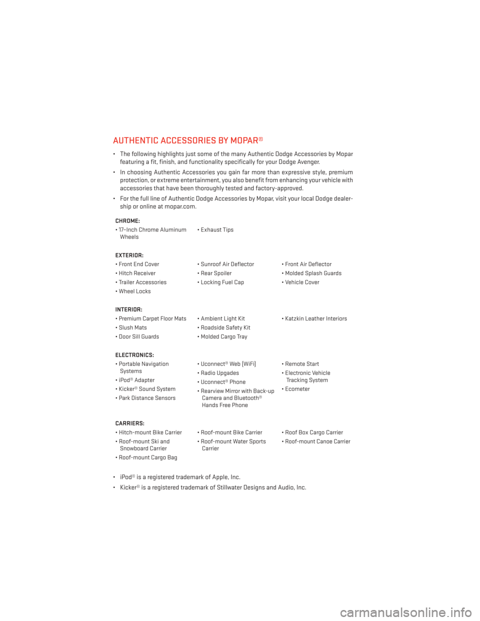
AUTHENTIC ACCESSORIES BY MOPAR®
• The following highlights just some of the many Authentic Dodge Accessories by Moparfeaturing a fit, finish, and functionality specifically for your Dodge Avenger.
• In choosing Authentic Accessories you gain far more than expressive style, premium protection, or extreme entertainment, you also benefit from enhancing your vehicle with
accessories that have been thoroughly tested and factory-approved.
• For the full line of Authentic Dodge Accessories by Mopar, visit your local Dodge dealer- ship or online at mopar.com.
CHROME:
• 17–Inch Chrome AluminumWheels • Exhaust Tips
EXTERIOR:
• Front End Cover • Sunroof Air Deflector • Front Air Deflector
• Hitch Receiver • Rear Spoiler • Molded Splash Guards
• Trailer Accessories • Locking Fuel Cap • Vehicle Cover
• Wheel Locks
INTERIOR:
•
Premium Carpet Floor Mats• Ambient Light Kit • Katzkin Leather Interiors
• Slush Mats • Roadside Safety Kit
• Door Sill Guards • Molded Cargo Tray
ELECTRONICS:
• Portable Navigation Systems • Uconnect® Web (WiFi) • Remote Start
• iPod® Adapter • Radio Upgades
• Electronic Vehicle
Tracking System
• Kicker® Sound System • Uconnect® Phone
• Ecometer
• Park Distance Sensors • Rearview Mirror with Back-up
Camera and Bluetooth®
Hands Free Phone
CARRIERS:
• Hitch-mount Bike Carrier • Roof-mount Bike Carrier • Roof Box Cargo Carrier
• Roof-mount Ski and Snowboard Carrier • Roof-mount Water Sports
Carrier •
Roof-mount Canoe Carrier
• Roof-mount Cargo Bag
• iPod® is a registered trademark of Apple, Inc.
• Kicker® is a registered trademark of Stillwater Designs and Audio, Inc.
MOPAR ACCESSORIES
100
Page 104 of 108
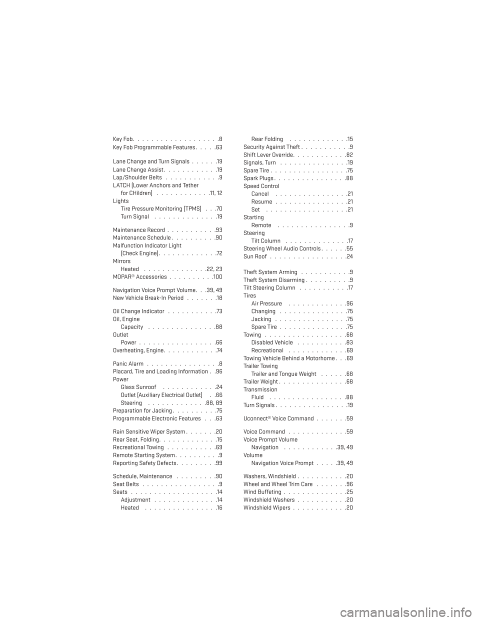
KeyFob...................8
Key Fob Programmable Features.....63
Lane Change and Turn Signals ......19
Lane Change Assist ............19
Lap/Shoulder Belts ............9
LATCH (Lower Anchors and Tether for CHildren) ............11, 12
Lights Tire Pressure Monitoring (TPMS) . . .70
TurnSignal ..............19
Maintenance Record ...........93
Maintenance Schedule ..........90
Malfunction Indicator Light (CheckEngine).............72
Mirrors Heated ..............22,23
MOPAR® Accessories ..........100
Navigation Voice Prompt Volume. . .39, 49
New Vehicle Break-In Period .......18
Oil Change Indicator ...........73
Oil, Engine Capacity ...............88
Outlet Power.................66
Overheating, Engine ............74
PanicAlarm................8
Placard, Tire and Loading Information . .96
Power Glass Sunroof ............24
Outlet (Auxiliary Electrical Outlet)..66
Steering .............88,89
Preparation for Jacking ..........75
Programmable Electronic Features . . .63
Rain Sensitive Wiper System .......20
Rear Seat, Folding .............15
Recreational Towing ...........69
Remote Starting System ..........9
Reporting Safety Defects .........99
Schedule,Maintenance .........90
Seat Belts .................9
Seats ...................14
Adjustment ..............14
Heated ................16 Rear Folding
.............15
Security Against Theft ...........9
Shift Lever Override ............82
Signals, Turn ...............19
SpareTire.................75
SparkPlugs................88
Speed Control Cancel ................21
Resume ................21
Set ..................21
Starting Remote ................9
Steering Tilt Column ..............17
Steering Wheel Audio Controls ......55
SunRoof.................24
Theft System Arming ...........9
Theft System Disarming ..........9
Tilt Steering Column ...........17
Tires Air Pressure .............96
Changing ...............75
Jacking ................75
SpareTire...............75
Towing ..................68 Disabled Vehicle ...........83
Recreational .............69
Towing Vehicle Behind a Motorhome . . .69
Trailer Towing Trailer and Tongue Weight ......68
Trailer Weight ...............68
Transmission Fluid .................88
Turn Signals ................19
Uconnect® Voice Command .......59
Voice Command .............59
Voice Prompt Volume Navigation ............39,49
Volume Navigation Voice Prompt .....39,49
Washers, Windshield ...........20
Wheel and Wheel Trim Care .......96
Wind Buffeting ..............25
Windshield Washers ...........20
Windshield Wipers ............20
INDEX
102