lights DODGE AVENGER 2013 2.G User Guide
[x] Cancel search | Manufacturer: DODGE, Model Year: 2013, Model line: AVENGER, Model: DODGE AVENGER 2013 2.GPages: 108, PDF Size: 3.35 MB
Page 3 of 108
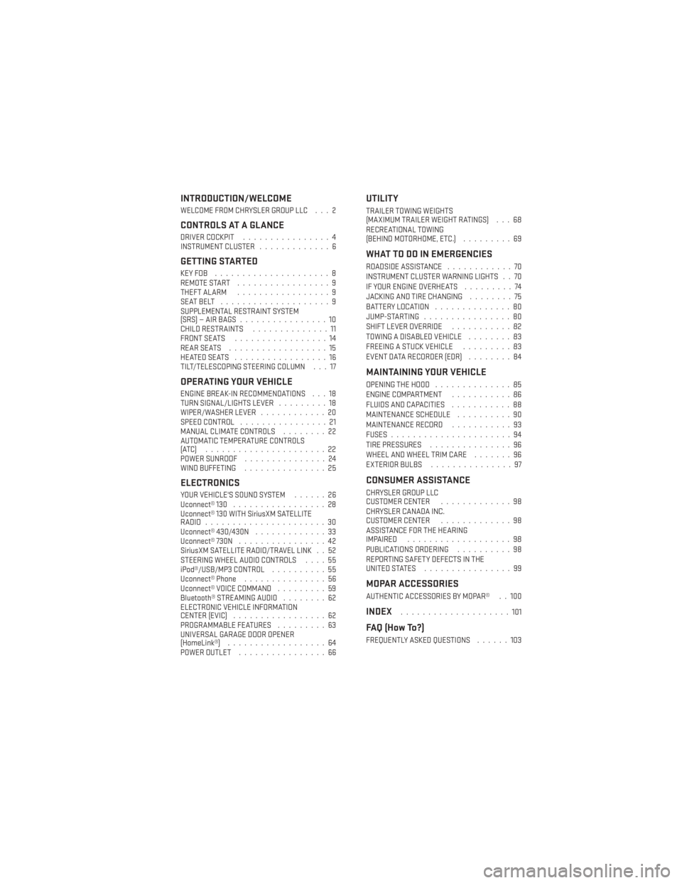
INTRODUCTION/WELCOME
WELCOME FROM CHRYSLER GROUP LLC . . . 2
CONTROLS AT A GLANCE
DRIVER COCKPIT................4
INSTRUMENT CLUSTER .............6
GETTING STARTED
KEYFOB .....................8
REMOTE START.................9
THEFT ALARM .................9
SEATBELT ....................9
SUPPLEMENTAL RESTRAINT SYSTEM
(SRS)—AIRBAGS................10
CHILD RESTRAINTS ..............11
FRONT SEATS .................14
REARSEATS ..................15
HEATEDSEATS .................16
TILT/TELESCOPING STEERING COLUMN . . . 17
OPERATING YOUR VEHICLE
ENGINE BREAK-IN RECOMMENDATIONS . . . 18
TURN SIGNAL/LIGHTS LEVER .........18
WIPER/WASHER LEVER ............20
SPEED CONTROL ................21
MANUAL CLIMATE CONTROLS ........22
AUTOMATIC TEMPERATURE CONTROLS
(ATC) ......................22
POWER SUNROOF ...............24
WIND BUFFETING ...............25
ELECTRONICS
YOUR VEHICLE'S SOUND SYSTEM ......26
Uconnect® 130 .................28
Uconnect® 130 WITH SiriusXM SATELLITE
RADIO ......................30
Uconnect® 430/430N .............33
Uconnect® 730N ................42
SiriusXM SATELLITE RADIO/TRAVEL LINK . . 52
STEERING WHEEL AUDIO CONTROLS ....55
iPod®/USB/MP3 CONTROL ..........55
Uconnect® Phone ...............56
Uconnect® VOICE COMMAND .........59
Bluetooth® STREAMING AUDIO ........62
ELECTRONIC VEHICLE INFORMATION
CENTER (EVIC) .................62
PROGRAMMABLE FEATURES .........63
UNIVERSAL GARAGE DOOR OPENER
(HomeLink®) ..................64
POWER OUTLET ................66
UTILITY
TRAILER TOWING WEIGHTS
(MAXIMUM TRAILER WEIGHT RATINGS) . . . 68
RECREATIONAL TOWING
(BEHIND MOTORHOME, ETC.) .........69
WHAT TO DO IN EMERGENCIES
ROADSIDE ASSISTANCE............70
INSTRUMENT CLUSTER WARNING LIGHTS . . 70
IF YOUR ENGINE OVERHEATS .........74
JACKING AND TIRE CHANGING ........75
BATTERY LOCATION ..............80
JUMP-STARTING ................80
SHIFT LEVER OVERRIDE ...........82
TOWING A DISABLED VEHICLE ........83
FREEING A STUCK VEHICLE .........83
EVENT DATA RECORDER (EDR) ........84
MAINTAINING YOUR VEHICLE
OPENING THE HOOD..............85
ENGINE COMPARTMENT ...........86
FLUIDS AND CAPACITIES ...........88
MAINTENANCE SCHEDULE ..........90
MAINTENANCE RECORD ...........93
FUSES ......................94
TIRE PRESSURES ...............96
WHEEL AND WHEEL TRIM CARE .......96
EXTERIOR BULBS ...............97
CONSUMER ASSISTANCE
CHRYSLER GROUP LLC
CUSTOMER CENTER .............98
CHRYSLER CANADA INC.
CUSTOMER CENTER .............98
ASSISTANCE FOR THE HEARING
IMPAIRED ...................98
PUBLICATIONS ORDERING ..........98
REPORTING SAFETY DEFECTS IN THE
UNITEDSTATES ................99
MOPAR ACCESSORIES
AUTHENTIC ACCESSORIES BY MOPAR® . . 100
INDEX....................101
FAQ (How To?)
FREQUENTLY ASKED QUESTIONS ......103
TABLE OF CONTENTS
Page 7 of 108
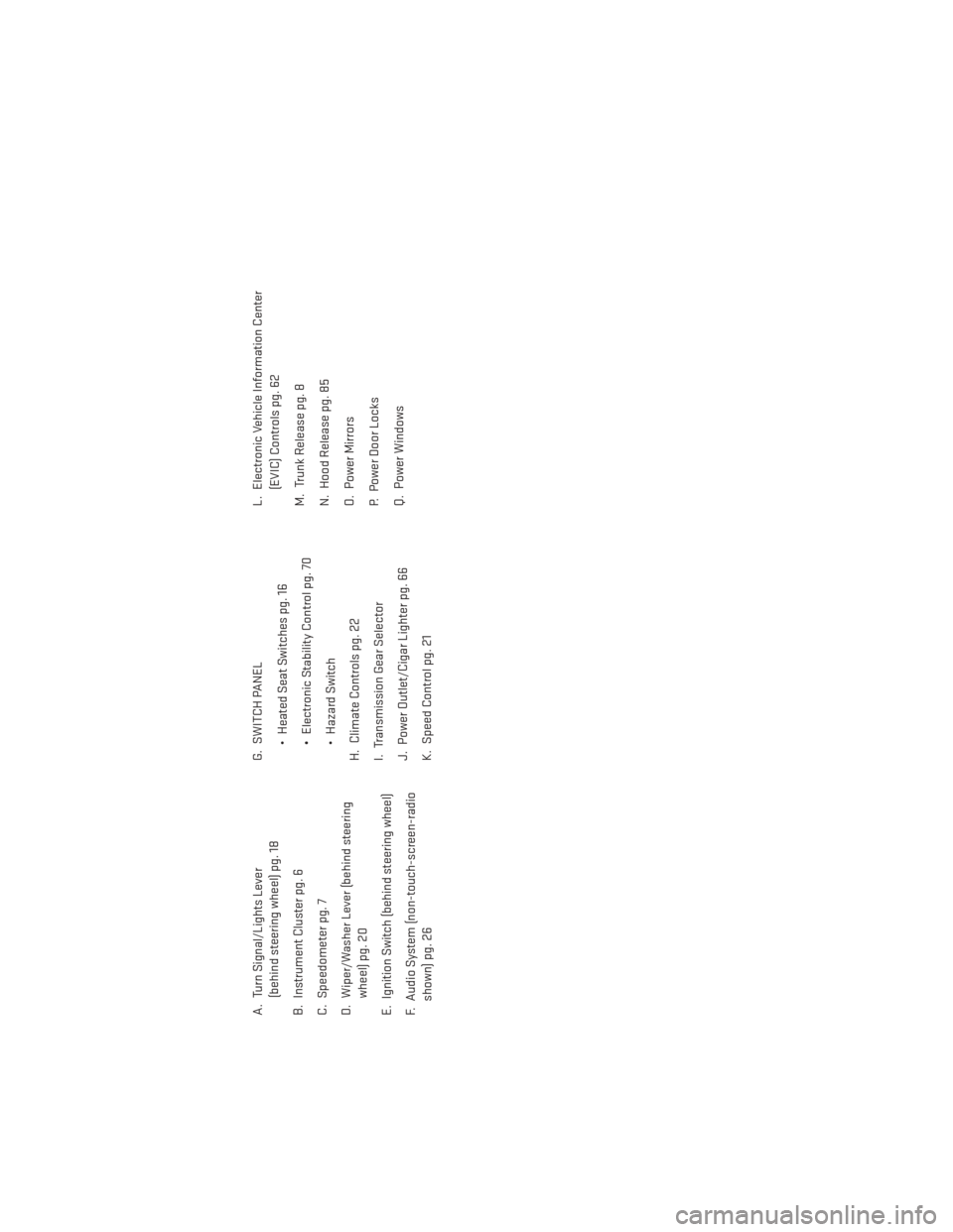
A. Turn Signal/Lights Lever(behind steering wheel) pg. 18
B. Instrument Cluster pg. 6
C. Speedometer pg. 7
D. Wiper/Washer Lever (behind steering wheel) pg. 20
E. Ignition Switch (behind steering wheel)
F. Audio System (non-touch-screen-radio shown) pg. 26 G. SWITCH PANEL
• Heated Seat Switches pg. 16
• Electronic Stability Control pg. 70
• Hazard Switch
H. Climate Controls pg. 22
I. Transmission Gear Selector
J. Power Outlet/Cigar Lighter pg. 66
K. Speed Control pg. 21 L. Electronic Vehicle Information Center
(EVIC) Controls pg. 62
M. Trunk Release pg. 8
N. Hood Release pg. 85
O. Power Mirrors
P. Power Door Locks
Q. Power Windows
CONTROLS AT A GLANCE
5
Page 8 of 108
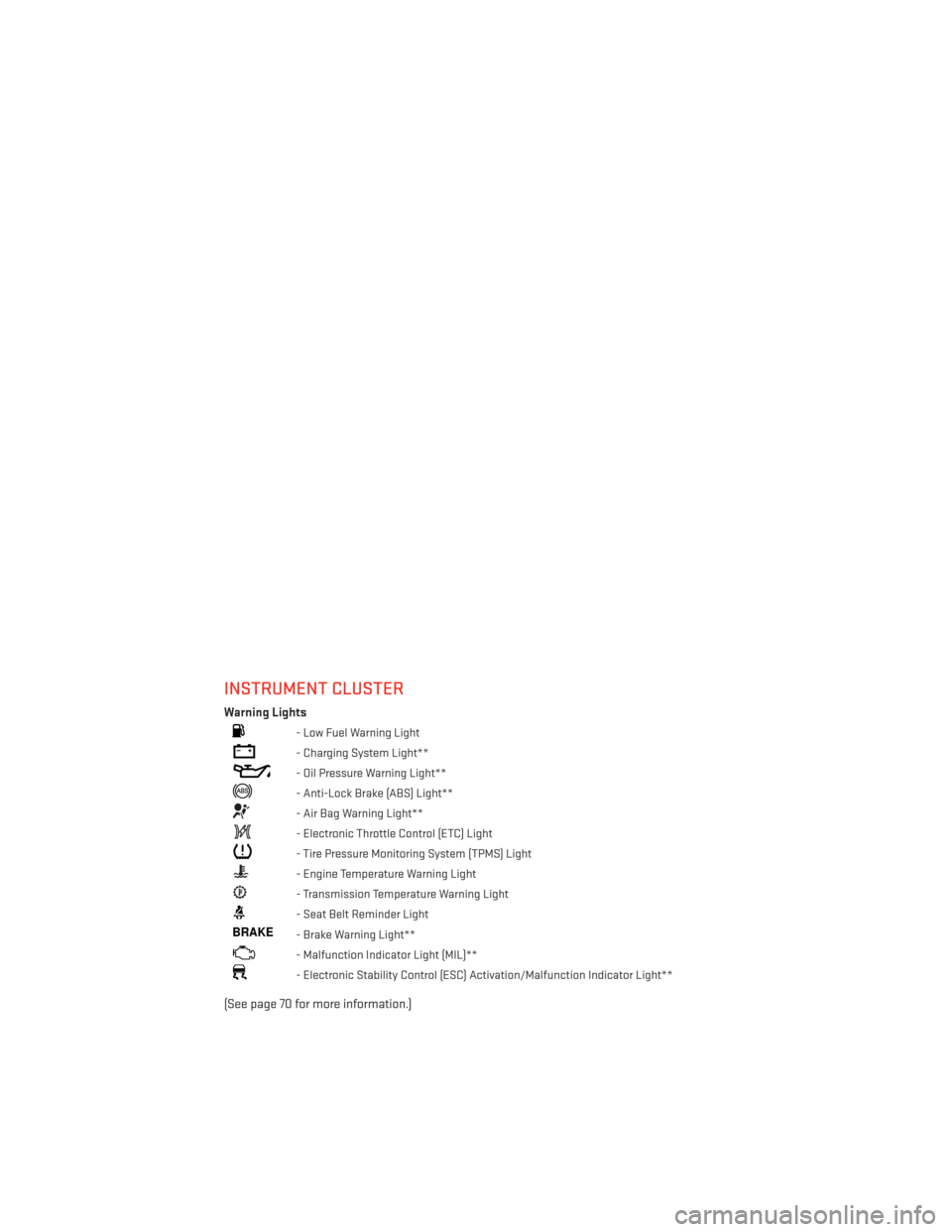
INSTRUMENT CLUSTER
Warning Lights
- Low Fuel Warning Light
- Charging System Light**
- Oil Pressure Warning Light**
- Anti-Lock Brake (ABS) Light**
- Air Bag Warning Light**
- Electronic Throttle Control (ETC) Light
- Tire Pressure Monitoring System (TPMS) Light
- Engine Temperature Warning Light
- Transmission Temperature Warning Light
- Seat Belt Reminder Light
BRAKE- Brake Warning Light**
- Malfunction Indicator Light (MIL)**
- Electronic Stability Control (ESC) Activation/Malfunction Indicator Light**
(See page 70 for more information.)
CONTROLS AT A GLANCE
6
Page 10 of 108
KEY FOB
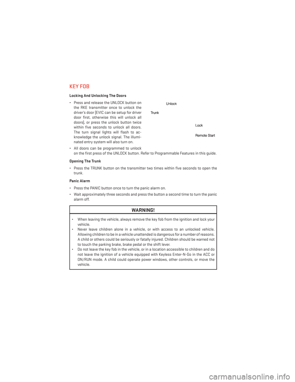
Locking And Unlocking The Doors
• Press and release the UNLOCK button onthe RKE transmitter once to unlock the
driver’s door (EVIC can be setup for driver
door first, otherwise this will unlock all
doors), or press the unlock button twice
within five seconds to unlock all doors.
The turn signal lights will flash to ac-
knowledge the unlock signal. The illumi-
nated entry system will also turn on.
• All doors can be programmed to unlock on the first press of the UNLOCK button. Refer to Programmable Features in this guide.
Opening The Trunk
• Press the TRUNK button on the transmitter two times within five seconds to open the trunk.
Panic Alarm
• Press the PANIC button once to turn the panic alarm on.
• Wait approximately three seconds and press the button a second time to turn the panic alarm off.
WARNING!
• When leaving the vehicle, always remove the key fob from the ignition and lock your
vehicle.
• Never leave children alone in a vehicle, or with access to an unlocked vehicle.
Allowing children to be in a vehicle unattended is dangerous for a number of reasons.
A child or others could be seriously or fatally injured. Children should be warned not
to touch the parking brake, brake pedal or the shift lever.
• Do not leave the key fob in the vehicle, or in a location accessible to children and do
not leave the ignition of a vehicle equipped with Keyless Enter-N-Go in the ACC or
ON/RUN mode. A child could operate power windows, other controls, or move the
vehicle.
GETTING STARTED
8
Page 20 of 108
ENGINE BREAK-IN RECOMMENDATIONS
• A long break-in period is not required for the engine and drivetrain (transmission andaxle) in your vehicle.
• Drive moderately during the first 300 miles (500 km). After the initial 60 miles (100 km), speeds up to 50 or 55 mph (80 or 90 km/h) are desirable.
•
While cruising, brief full-throttle acceleration within the limits of local traffic laws con-
tributes to a good break-in. Wide-open throttle acceleration in low gear can be detrimental
and should be avoided.
• The engine oil installed in the engine at the factory is a high-quality energy conserving type lubricant. Oil changes should be consistent with anticipated climate conditions
under which vehicle operations will occur. For the recommended viscosity and quality
grades, refer to “Maintaining Your Vehicle”.
NOTE:
A new engine may consume some oil during its first few thousand miles (kilometers) of
operation. This should be considered a normal part of the break-in and not interpreted as an
indication to an engine problem or malfunction.
CAUTION!
Never use Non-Detergent Oil or Straight Mineral Oil in the engine or damage may result.
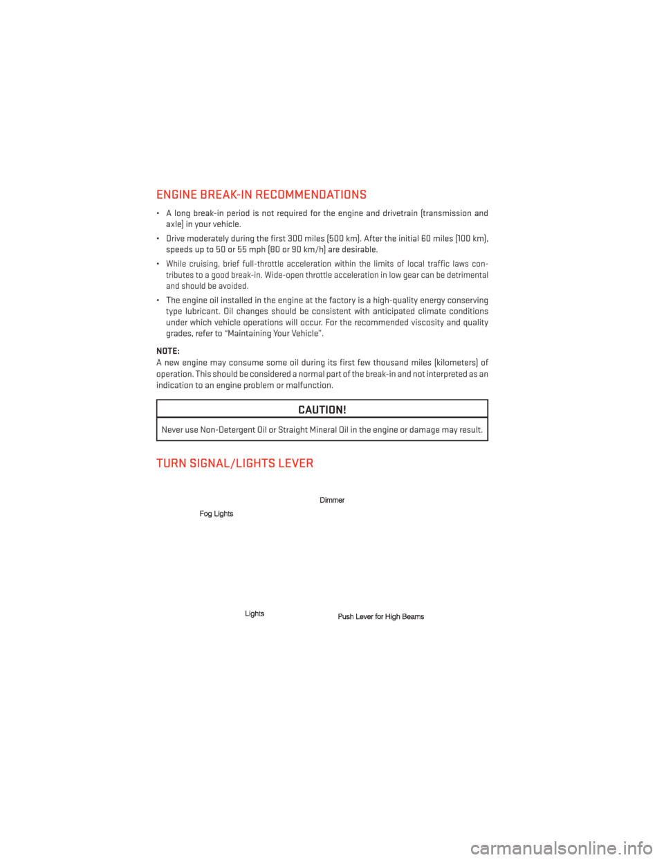
TURN SIGNAL/LIGHTS LEVER
OPERATING YOUR VEHICLE
18
Page 21 of 108
Headlights/Parking Lights/Automatic Headlights
• Rotate the end of the lever to the first detent for parking lights
, the second detent
for headlights
, and the third detent for AUTO.
• When set to AUTO, the system automatically turns the headlights on or off based on ambient light levels.
Instrument Panel Dimmer
• Rotate the center portion of the lever to the extreme bottom position to fully dim the instrument panel lights and prevent the interior lights from illuminating when a door is
opened.
• Rotate the center portion of the lever up to increase the brightness of the instrument panel lights when the parking lights or headlights are on.
• Rotate the center portion of the lever upward to the next detent position to brighten the odometer and radio controls when the parking lights or headlights are on.
• Rotate the center portion of the lever upward to the last detent to turn on the interior lighting.
Flash To Pass
• Pull the lever toward you to activate the high beams. The high beams will remain on until the lever is released.
High Beam Operation
• Push the lever forward to activate the high beams.
NOTE:
For safe driving, turn off the high beams when oncoming traffic is present to prevent
headlight glare and as a courtesy to other motorists.
Front Fog Lights
• Turn on the parking lights or low beam headlights and pull out the end of the lever.
Turn Signals/Lane Change Assist
• Tap the lever up or down once and the turn signal (right or left) will flash three times and automatically turn off.
OPERATING YOUR VEHICLE
19
Page 65 of 108
PROGRAMMABLE FEATURES
Electronic Vehicle Information Center (EVIC)
• The EVIC can be used to program the following Personal Settings. Press and release theMENU button until Personal Settings displays, then press the DOWN button
to scroll
through the settings. Press the SELECT button
to change the setting.
• Language • Headlights With Wipers
(Available with Auto Headlights Only)
• Auto Unlock On Exit
• Key Off Power Delay
• RKE Unlock
• Illumin. Approach
• Sound Horn With Lock
• Display Units In
• Flash Lamps With Lock
• Calibrate Compass
• Headlamp Off Delay
• Compass Variance
Key Fob Programmable Features
• The following features may also be programmed by using the Key Fob transmitter or the
ignition switch and driver's door lock switch.
NOTE:
Pressing the LOCK button while you are inside the vehicle will activate the Vehicle Security
Alarm. Opening a door with the Vehicle Security Alarm activated will cause the alarm to
sound. Press the UNLOCK button to deactivate the Vehicle Security Alarm.
Unlock On First Press
• To unlock either the driver's side, or all doors, on the first press of the UNLOCK button: •
Press and hold the LOCK button for at least four seconds, but no longer than 10 seconds.
Then, press and hold the UNLOCK button while still holding the LOCK button.
• Release both buttons at the same time.
Auto Unlock Doors On Exit
• To have all of the vehicle doors unlock when any door is opened:• Enter your vehicle and close all the doors, and fasten your seat belt.
• Cycle the ignition switch between the LOCK and ON position four times, ending in the
LOCK position (do not start the engine).
• Press the power door UNLOCK switch to unlock the doors. A single chime will indicate that programming is complete.
Sound Horn With Lock
• To turn the horn chirp on or off when the doors are locked: • Press the LOCK button for at least four seconds, but no longer than 10 seconds. Then,
press the PANIC button while still holding the LOCK button.
• Release both buttons at the same time.
Flashing Lights With Lock
• The turn signal lights flashing, when the doors are locked or unlocked, feature can be turned on or off. To turn this feature on or off:•
Press and hold the UNLOCK button for at least four seconds, but no longer than 10 sec-
onds. Then, press and hold the LOCK button while still holding the UNLOCK button.
• Release both buttons at the same time.
ELECTRONICS
63
Page 72 of 108
ROADSIDE ASSISTANCE
•Dial toll-free 1-800-521-2779 for U.S. Residents or 1-800-363-4869 for Canadian Residents.
•Provide your name, vehicle identification number, license plate number, and your location,
including the telephone number from which you are calling.
• Briefly describe the nature of the problem and answer a few simple questions.
•
You will be given the name of the service provider and an estimated time of arrival. If you feel
you are in an “unsafe situation”, please let us know. With your consent, we will contact local
police or safety authorities.
INSTRUMENT CLUSTER WARNING LIGHTS
- Electronic Stability Control (ESC) Activation/Malfunction Indicator Light
• If the “ESC Activation/Malfunction Indicator Light” comes on continuously with the engine running, a malfunction has been detected in the ESC system. If this light remains
on after several ignition cycles, and the vehicle has been driven several miles (kilo-
meters) at speeds greater than 30 mph (48 km/h), we recommend you do not operate the
vehicle. Have the vehicle serviced immediately.
• The “ESC Activation/Malfunction Indicator Light” starts to flash as soon as the tires lose traction and the ESC system becomes active. If the light begins to flash during accel-
eration, ease up on the accelerator and apply as little throttle as possible. Be sure to
adapt your speed and driving to the prevailing road conditions. The light also flashes
when TCS is active. To improve the vehicle's traction when starting off in deep snow, sand
or gravel, it may be desirable to switch the ESC system to Partial Off mode by momen-
tarily pressing the ESC Off
switch.
- Tire Pressure Monitoring System (TPMS) Light
• Each tire, including the spare (if provided), should be checked monthly, when cold and inflated to the inflation pressure recommended by the vehicle manufacturer on the
vehicle placard or tire inflation pressure label. (If your vehicle has tires of a different size
than the size indicated on the vehicle placard or tire inflation pressure label, you should
determine the proper tire inflation pressure for those tires.)
• As an added safety feature, your vehicle has been equipped with a Tire Pressure Moni- toring System (TPMS) that illuminates a low tire pressure telltale when one or more of
your tires is significantly under-inflated. Accordingly, when the low tire pressure telltale
illuminates, you should stop and check your tires as soon as possible, and inflate them to
the proper pressure. Driving on a significantly under-inflated tire causes the tire to
overheat and can lead to tire failure. Under-inflation also reduces fuel efficiency and tire
tread life, and may affect the vehicle’s handling and stopping ability.
• IF THE LIGHT STARTS FLASHING INDICATING A LOW TIRE PRESSURE, ADJUST THE
AIR PRESSURE IN THE LOW TIRE TO THE AIR PRESSURE SHOWN ON THE VEHICLE
PLACARD OR TIRE INFLATION PRESSURE LABEL LOCATED ON THE DRIVER'S DOOR.
WHAT TO DO IN EMERGENCIES
70
Page 92 of 108
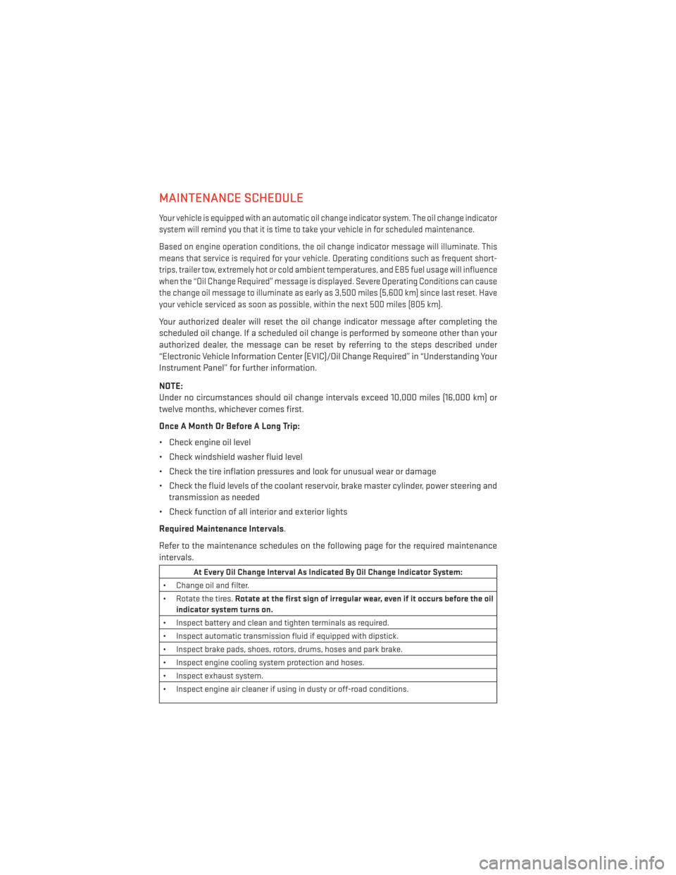
MAINTENANCE SCHEDULE
Your vehicle is equipped with an automatic oil change indicator system. The oil change indicator
system will remind you that it is time to take your vehicle in for scheduled maintenance.
Based on engine operation conditions, the oil change indicator message will illuminate. This
means that service is required for your vehicle. Operating conditions such as frequent short-
trips, trailer tow, extremely hot or cold ambient temperatures, and E85 fuel usage will influence
when the “Oil Change Required” message is displayed. Severe Operating Conditions can cause
the change oil message to illuminate as early as 3,500 miles (5,600 km) since last reset. Have
your vehicle serviced as soon as possible, within the next 500 miles (805 km).
Your authorized dealer will reset the oil change indicator message after completing the
scheduled oil change. If a scheduled oil change is performed by someone other than your
authorized dealer, the message can be reset by referring to the steps described under
“Electronic Vehicle Information Center (EVIC)/Oil Change Required” in “Understanding Your
Instrument Panel” for further information.
NOTE:
Under no circumstances should oil change intervals exceed 10,000 miles (16,000 km) or
twelve months, whichever comes first.
Once A Month Or Before A Long Trip:
• Check engine oil level
• Check windshield washer fluid level
• Check the tire inflation pressures and look for unusual wear or damage
• Check the fluid levels of the coolant reservoir, brake master cylinder, power steering andtransmission as needed
• Check function of all interior and exterior lights
Required Maintenance Intervals.
Refer to the maintenance schedules on the following page for the required maintenance
intervals.
At Every Oil Change Interval As Indicated By Oil Change Indicator System:
• Change oil and filter.
• Rotate the tires. Rotate at the first sign of irregular wear, even if it occurs before the oil
indicator system turns on.
• Inspect battery and clean and tighten terminals as required.
• Inspect automatic transmission fluid if equipped with dipstick.
• Inspect brake pads, shoes, rotors, drums, hoses and park brake.
• Inspect engine cooling system protection and hoses.
• Inspect exhaust system.
• Inspect engine air cleaner if using in dusty or off-road conditions.
MAINTAINING YOUR VEHICLE
90
Page 96 of 108
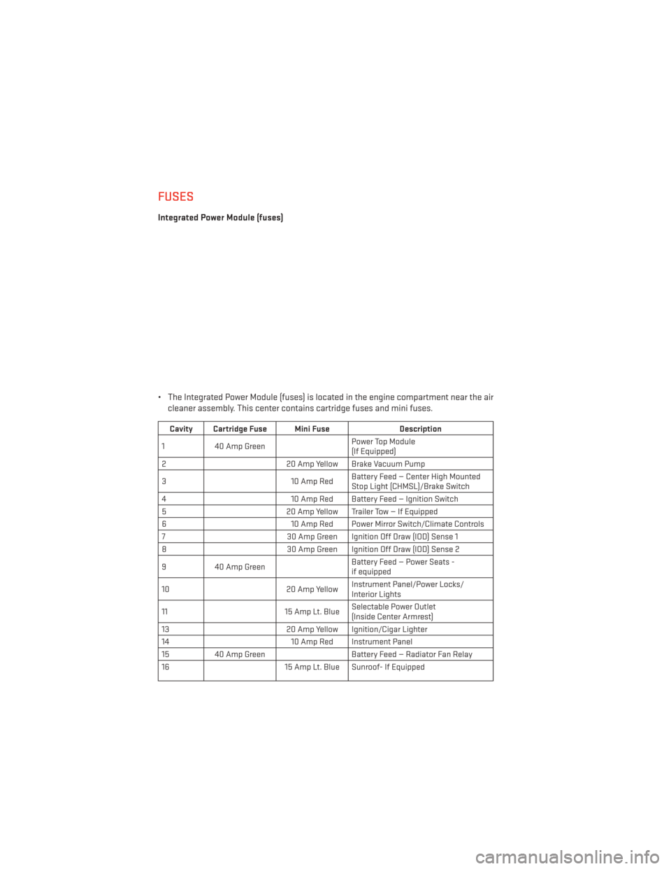
FUSES
Integrated Power Module (fuses)
• The Integrated Power Module (fuses) is located in the engine compartment near the aircleaner assembly. This center contains cartridge fuses and mini fuses.
Cavity Cartridge Fuse Mini Fuse Description
1 40 Amp Green Power Top Module
(If Equipped)
2 20 Amp Yellow Brake Vacuum Pump
3 10 Amp RedBattery Feed — Center High Mounted
Stop Light (CHMSL)/Brake Switch
4 10 Amp Red Battery Feed — Ignition Switch
5 20 Amp Yellow Trailer Tow — If Equipped
6 10 Amp Red Power Mirror Switch/Climate Controls
7 30 Amp Green Ignition Off Draw (IOD) Sense 1
8 30 Amp Green Ignition Off Draw (IOD) Sense 2
9 40 Amp Green Battery Feed — Power Seats -
if equipped
10 20 Amp YellowInstrument Panel/Power Locks/
Interior Lights
11 15 Amp Lt. BlueSelectable Power Outlet
(Inside Center Armrest)
13 20 Amp Yellow Ignition/Cigar Lighter
14 10 Amp Red Instrument Panel
15 40 Amp Green Battery Feed — Radiator Fan Relay
16 15 Amp Lt. Blue Sunroof- If Equipped
MAINTAINING YOUR VEHICLE
94