lock DODGE AVENGER 2014 2.G Owner's Manual
[x] Cancel search | Manufacturer: DODGE, Model Year: 2014, Model line: AVENGER, Model: DODGE AVENGER 2014 2.GPages: 124, PDF Size: 3.24 MB
Page 82 of 124
- Air Bag Warning Light
• If the light is not on during starting, stays on, or turns on while driving, have the vehicleserviced by an authorized dealer immediately.
Fuel Cap/Loose Gas Cap Message
• If a “gas cap” message (shown as Check Fuel Cap) appears, tighten the gas cap until a“clicking” sound is heard.
• Press the odometer reset button to turn the message off.
• If the message continues to appear for more than three days after tightening the gas cap, see your authorized service center.
Oil Change Indicator
Message
• If an “oil change” message (shown as CHANgE OIL) appears and a single chime sounds,it is time for your next required oil change.
Resetting The Light After Servicing
• Turn the ignition switch to the ON/RUN position (do not start engine).
• Fully depress the accelerator pedal three times within 10 seconds.
• Turn the ignition switch to the OFF/LOCK position.
IF YOUR ENGINE OVERHEATS
• In any of the following situations, you can reduce the potential for overheating by taking the appropriate action.• On the highways — slow down.
• In city traffic — while stopped, shift transmission into NEUTRAL, but do not increase
engine idle speed.
NOTE:
There are steps that you can take to slow down an impending overheat condition:
• If your air conditioner (A/C) is on, turn it off. The A/C system adds heat to the engine cooling system and turning the A/C off can help remove this heat.
• You can also turn the Temperature Control to maximum heat, the Mode Control to floor and the Fan Control to high. This allows the heater core to act as a supplement to the
radiator and aids in removing heat from the engine cooling system.
• If the temperature reading does not return to normal, turn the engine off immediately.
• We recommend that you do not operate the vehicle or engine damage will occur. Have the vehicle serviced immediately.
WHAT TO DO IN EMERGENCIES
80
Page 84 of 124
Preparations For Jacking
1. Park the vehicle on a firm, level surface. Avoid ice or slippery areas.
2. Turn on the Hazard Warning flashers.
3. Set the parking brake.
4. Place the shift lever into PARK (automatic transmission) or REVERSE (manual transmis-sion).
5. Turn OFF the ignition.
6. Block both the front and rear of the wheel diagonally opposite the jacking position. For example, if changing the right front tire, block the left rear wheel.
NOTE:
Passengers should not remain in the vehicle
while the vehicle is being jacked.
Jacking Instructions
1. Remove the scissors jack and lug wrench from the spare wheel as an assembly.
Turn the jack screw to the left to loosen
the lug wrench, and remove the wrench
from the jack assembly.
WHAT TO DO IN EMERGENCIES
82
Page 86 of 124
6. Remove the wheel nuts, and pull the wheel and wheel covers (where applicable) off thehub. Install the spare wheel and wheel nuts with the cone shaped end of the nuts toward
the wheel. Lightly tighten the nuts.
7. Lower the vehicle by turning the jack screw to the left.
8.
Finish tightening the nuts. Push down on
the wrench while at the end of the handle for
increased leverage. Tighten the lug nuts in a
star pattern until each nut has been tight-
ened twice. The correct wheel nut torque is
100 ft lbs (135 N·m). If you doubt that you
have tightened the nuts correctly, have
them checked with a torque wrench by your
authorized dealer or at a service station.
9. Remove the wheel blocks and lower the jack until it is free. Reassemble the lug wrench to the jack assembly and stow it in the spare tire area. Secure the assembly using the
means provided.
10. Place the deflated (flat) tire in the cargo area and have the tire repaired or replaced as
soon as possible.
11. Check the tire pressure as soon as possible. Correct the tire pressure as required.
Road Tire Installation
Vehicles Equipped With Wheel Covers
1. Mount the road tire on the axle.
2. To ease the installation process for steel wheels with wheel covers, install two lug nuts on the mounting studs which are on each side of the valve stem. Install the lug nuts with
the cone shaped end of the nut toward the wheel. Lightly tighten the lug nuts.
1 — Valve Stem 4 — Wheel Cover
2 — Valve Notch 5 — Mounting Stud
3 — Wheel Lug Nut
WHAT TO DO IN EMERGENCIES
84
Page 87 of 124

3. Align the valve notch in the wheel cover with the valve stem on the wheel. Install thecover by hand, snapping the cover over the two lug nuts. Do not use a hammer or
excessive force to install the cover.
4. Install the remaining lug nuts with the cone shaped end of the nut toward the wheel. Lightly tighten the lug nuts.
5. Lower the vehicle to the ground by turning the jack handle counterclockwise.
6. Finish tightening the lug nuts. Push down on the wrench while at the end of the handle for increased leverage. Tighten the lug nuts in a star pattern until each nut has been
tightened twice. The correct tightness of each lug nut is 100 ft/lbs (135 N·m). If in doubt
about the correct tightness, have them checked with a torque wrench by your authorized
dealer or service station.
7. After 25 miles (40 km) check the lug nut torque with a torque wrench to ensure that all lug nuts are properly seated against the wheel.
Vehicles Without Wheel Covers
1. Mount the road tire on the axle.
2. Install the remaining lug nuts with the cone shaped end of the nut toward the wheel. Lightly tighten the lug nuts.
3. Lower the vehicle to the ground by turning the jack handle counterclockwise.
4. Finish tightening the lug nuts. Push down on the wrench while at the end of the handle for increased leverage. Tighten the lug nuts in a star pattern until each nut has been
tightened twice. The correct tightness of each lug nut is 100 ft/lbs (135 N·m). If in doubt
about the correct tightness, have them checked with a torque wrench by your authorized
dealer or service station.
5. After 25 miles (40 km) check the lug nut torque with a torque wrench to ensure that all lug nuts are properly seated against the wheel.
CAUTION!
• Do not attempt to raise the vehicle by jacking on locations other than those indicated in the Jacking Instructions for this vehicle.
• Be sure to mount the spare tire with the valve stem facing outward. The vehicle could
be damaged if the spare tire is mounted incorrectly.
WHAT TO DO IN EMERGENCIES
85
Page 88 of 124
WARNING!
• Being under a jacked-up vehicle is dangerous. The vehicle could slip off the jack andfall on you. You could be crushed. Never put any part of your body under a vehicle that
is on a jack. If you need to get under a raised vehicle, take it to a service center where
it can be raised on a lift.
• Never start or run the engine while the vehicle is on a jack.
• The jack is designed to be used as a tool for changing tires only. The jack should not
be used to lift the vehicle for service purposes. The vehicle should be jacked on a firm
level surface only. Avoid ice or slippery areas.
• Do not attempt to change a tire on the side of the vehicle close to moving traffic, pull
far enough off the road to avoid the danger of being hit when operating the jack or
changing the wheel.
• Carefully follow these tire changing warnings to help prevent personal injury or
damage to your vehicle:
• Always park on a firm, level surface as far from the edge of the roadway as pos-sible before raising the vehicle.
• Turn on the Hazard Warning flasher.
• Block the wheel diagonally opposite the wheel to be raised.
• Set the parking brake firmly and set an automatic transmission in PARK; a
manual transmission in REVERSE.
• Do not let anyone sit in the vehicle when it is on a jack.
• Do not get under the vehicle when it is on a jack.
• Only use the jack in the positions indicated and for lifting this vehicle during a tire
change.
• If working on or near a roadway, be extremely careful of motor traffic.
• To assure that spare tires, flat or inflated, are securely stowed, spares must be
stowed with the valve stem facing the ground.
• Raising the vehicle higher than necessary can make the vehicle less stable. It could
slip off the jack and hurt someone near it. Raise the vehicle only enough to remove
the tire.
• To avoid possible personal injury, handle the wheel covers with care to avoid contact
with any sharp edges.
• A loose tire or jack thrown forward in a collision or hard stop could injure the
occupants in the vehicle. Have the deflated (flat) tire repaired or replaced immedi-
ately.
• To avoid the risk of forcing the vehicle off the jack, do not tighten the lug nuts fully
until the vehicle is lowered to the ground. Failure to follow this warning may result in
personal injury.
WHAT TO DO IN EMERGENCIES
86
Page 90 of 124
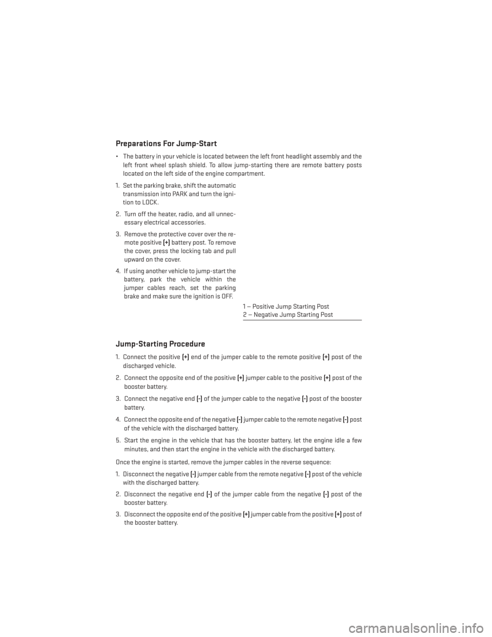
Preparations For Jump-Start
• The battery in your vehicle is located between the left front headlight assembly and theleft front wheel splash shield. To allow jump-starting there are remote battery posts
located on the left side of the engine compartment.
1. Set the parking brake, shift the automatic transmission into PARK and turn the igni-
tion to LOCK.
2. Turn off the heater, radio, and all unnec- essary electrical accessories.
3. Remove the protective cover over the re- mote positive (+)battery post. To remove
the cover, press the locking tab and pull
upward on the cover.
4. If using another vehicle to jump-start the battery, park the vehicle within the
jumper cables reach, set the parking
brake and make sure the ignition is OFF.
Jump-Starting Procedure
1. Connect the positive (+)end of the jumper cable to the remote positive (+)post of the
discharged vehicle.
2. Connect the opposite end of the positive (+)jumper cable to the positive (+)post of the
booster battery.
3. Connect the negative end (-)of the jumper cable to the negative (-)post of the booster
battery.
4. Connect the opposite end of the negative (-)jumper cable to the remote negative (-)post
of the vehicle with the discharged battery.
5. Start the engine in the vehicle that has the booster battery, let the engine idle a few minutes, and then start the engine in the vehicle with the discharged battery.
Once the engine is started, remove the jumper cables in the reverse sequence:
1. Disconnect the negative (-)jumper cable from the remote negative (-)post of the vehicle
with the discharged battery.
2. Disconnect the negative end (-)of the jumper cable from the negative (-)post of the
booster battery.
3. Disconnect the opposite end of the positive (+)jumper cable from the positive (+)post of
the booster battery.
1 — Positive Jump Starting Post
2 — Negative Jump Starting Post
WHAT TO DO IN EMERGENCIES
88
Page 96 of 124
OPENING THE HOOD
1. Pull the release lever located below theinstrument panel and in front of the driv-
er’s door.
2. Raise the hood and locate the safety latch, in the middle of the hood opening.
3. Move the safety latch while lifting the hood at the same time.
4. Insert the support rod into the slot on the hood.
5. To close the hood, remove the support rod and place it in the retaining clip, then
lower the hood slowly.
WARNING!
Be sure the hood is fully latched before driving your vehicle. If the hood is not fully
latched, it could open when the vehicle is in motion and block your vision. Failure to
follow this warning could result in serious injury or death.
MAINTAINING YOUR VEHICLE
94
Page 106 of 124
FUSES
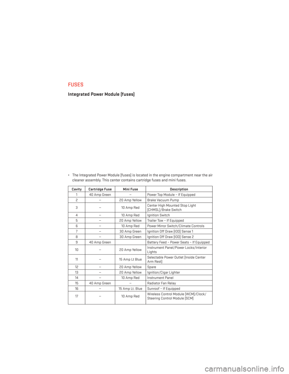
Integrated Power Module (fuses)
• The Integrated Power Module (fuses) is located in the engine compartment near the aircleaner assembly. This center contains cartridge fuses and mini fuses.
Cavity Cartridge Fuse Mini Fuse Description
1 40 Amp Green — Power Top Module – If Equipped
2 — 20 Amp Yellow Brake Vacuum Pump
3 —10 Amp Red Center High Mounted Stop Light
(CHMSL)/Brake Switch
4 —10 Amp Red Ignition Switch
5 — 20 Amp Yellow Trailer Tow – If Equipped
6 —10 Amp Red Power Mirror Switch/Climate Controls
7 — 30 Amp Green Ignition Off Draw (IOD) Sense 1
8 — 30 Amp Green Ignition Off Draw (IOD) Sense 2
9 40 Amp Green Battery Feed – Power Seats – If Equipped
10 — 20 Amp Yellow Instrument Panel/Power Locks/Interior
Lights
11 — 15 Amp Lt Blue Selectable Power Outlet (Inside Center
Arm Rest)
12 — 20 Amp Yellow Spare
13 — 20 Amp Yellow Ignition/Cigar Lighter
14 —10 Amp Red Instrument Panel
15 40 Amp Green — Radiator Fan Relay 16 — 15 Amp Lt. Blue Sunroof – If Equipped
17 —10 Amp Red Wireless Control Module (WCM)/Clock/
Steering Control Module (SCM)
MAINTAINING YOUR VEHICLE
104
Page 107 of 124
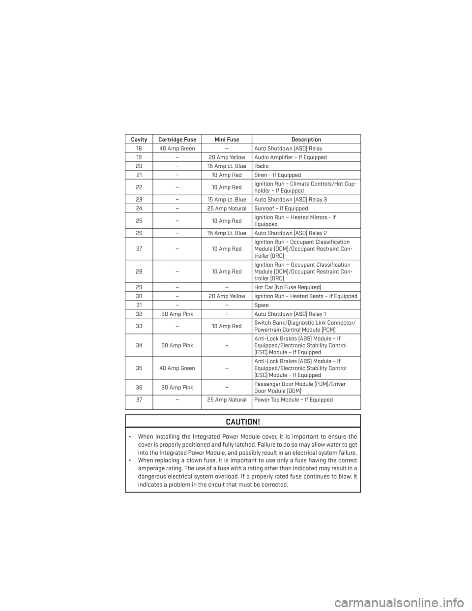
Cavity Cartridge Fuse Mini FuseDescription
18 40 Amp Green — Auto Shutdown (ASD) Relay 19 — 20 Amp Yellow Audio Amplifier – If Equipped
20 — 15 Amp Lt. Blue Radio
21 —10 Amp Red Siren – If Equipped
22 —10 Amp Red Ignition Run – Climate Controls/Hot Cup-
holder – If Equipped
23 — 15 Amp Lt. Blue Auto Shutdown (ASD) Relay 3
24 — 25 Amp Natural Sunroof – If Equipped
25 —10 Amp Red Ignition Run — Heated Mirrors - If
Equipped
26 — 15 Amp Lt. Blue Auto Shutdown (ASD) Relay 2
27 —10 Amp Red Ignition Run – Occupant Classification
Module (OCM)/Occupant Restraint Con-
troller (ORC)
28 —10 Amp Red Ignition Run — Occupant Classification
Module (OCM)/Occupant Restraint Con-
troller (ORC)
29 — — Hot Car (No Fuse Required)
30 — 20 Amp Yellow Ignition Run – Heated Seats – If Equipped
31 — — Spare
32 30 Amp Pink — Auto Shutdown (ASD) Relay 1
33 —10 Amp Red Switch Bank/Diagnostic Link Connector/
Powertrain Control Module (PCM)
34 30 Amp Pink —Anti-Lock Brakes (ABS) Module – If
Equipped/Electronic Stability Control
(ESC) Module – If Equipped
35 40 Amp Green — Anti-Lock Brakes (ABS) Module – If
Equipped/Electronic Stability Control
(ESC) Module – If Equipped
36 30 Amp Pink —Passenger Door Module (PDM)/Driver
Door Module (DDM)
37 — 25 Amp Natural Power Top Module – If Equipped
CAUTION!
• When installing the Integrated Power Module cover, it is important to ensure the
cover is properly positioned and fully latched. Failure to do so may allow water to get
into the Integrated Power Module, and possibly result in an electrical system failure.
• When replacing a blown fuse, it is important to use only a fuse having the correct
amperage rating. The use of a fuse with a rating other than indicated may result in a
dangerous electrical system overload. If a properly rated fuse continues to blow, it
indicates a problem in the circuit that must be corrected.
MAINTAINING YOUR VEHICLE
105
Page 112 of 124
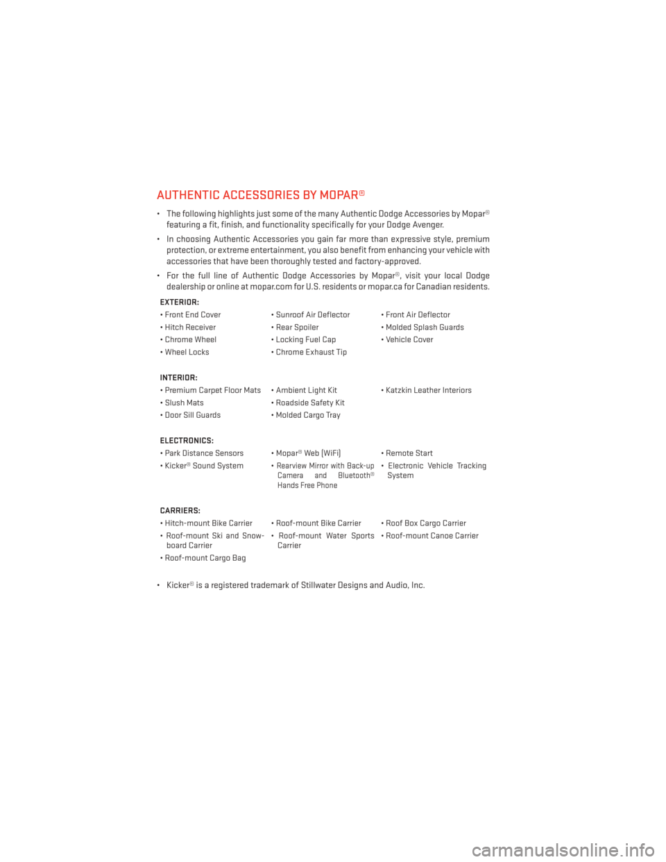
AUTHENTIC ACCESSORIES BY MOPAR®
• The following highlights just some of the many Authentic Dodge Accessories by Mopar®featuring a fit, finish, and functionality specifically for your Dodge Avenger.
• In choosing Authentic Accessories you gain far more than expressive style, premium protection, or extreme entertainment, you also benefit from enhancing your vehicle with
accessories that have been thoroughly tested and factory-approved.
• For the full line of Authentic Dodge Accessories by Mopar®, visit your local Dodge dealership or online at mopar.com for U.S. residents or mopar.ca for Canadian residents.
EXTERIOR:
• Front End Cover • Sunroof Air Deflector • Front Air Deflector
• Hitch Receiver • Rear Spoiler• Molded Splash Guards
• Chrome Wheel • Locking Fuel Cap• Vehicle Cover
• Wheel Locks • Chrome Exhaust Tip
INTERIOR:
• Premium Carpet Floor Mats • Ambient Light Kit • Katzkin Leather Interiors
• Slush Mats • Roadside Safety Kit
• Door Sill Guards • Molded Cargo Tray
ELECTRONICS:
• Park Distance Sensors • Mopar® Web (WiFi) • Remote Start
• Kicker® Sound System •
Rearview Mirror with Back-up Camera and Bluetooth®
Hands Free Phone• Electronic Vehicle Tracking System
CARRIERS:
• Hitch-mount Bike Carrier • Roof-mount Bike Carrier • Roof Box Cargo Carrier
• Roof-mount Ski and Snow- board Carrier • Roof-mount Water Sports
Carrier • Roof-mount Canoe Carrier
• Roof-mount Cargo Bag
• Kicker® is a registered trademark of Stillwater Designs and Audio, Inc.
MOPAR® ACCESSORIES
110