climate control DODGE AVENGER 2014 2.G User Guide
[x] Cancel search | Manufacturer: DODGE, Model Year: 2014, Model line: AVENGER, Model: DODGE AVENGER 2014 2.GPages: 124, PDF Size: 3.24 MB
Page 3 of 124
INTRODUCTION/WELCOME
WELCOME FROM CHRYSLER GROUP LLC . . . 2
CONTROLS AT A GLANCE
DRIVER COCKPIT................4
INSTRUMENT CLUSTER .............6
GETTING STARTED
KEYFOB .....................8
REMOTE START.................9
TRUNK LOCK AND RELEASE ..........9
SECURITY ALARM ...............10
SEATBELT ...................11
SUPPLEMENTAL RESTRAINT SYSTEM
(SRS)—AIRBAGS ................11
CHILD RESTRAINTS ..............12
FRONT SEATS .................16
REARSEATS ..................18
HEATEDSEATS .................18
TILT/TELESCOPING STEERING COLUMN . . . 19
OPERATING YOUR VEHICLE
ENGINE BREAK-IN RECOMMENDATIONS . . . 20
TURN SIGNAL/LIGHTS LEVER .........20
WIPER/WASHER LEVER ............22
SPEED CONTROL ................23
MANUAL CLIMATE CONTROLS ........25
AUTOMATIC TEMPERATURE CONTROLS
(ATC) ......................26
POWER SUNROOF ...............27
WIND BUFFETING ...............29
ELECTRONICS
YOUR VEHICLE'S SOUND SYSTEM ......30
Uconnect® 130 .................32
Uconnect® 130 WITH SiriusXM SATELLITE
RADIO ......................34
Uconnect® 430/430N .............37
Uconnect® 730N ................46
SiriusXM SATELLITE RADIO/TRAVEL LINK . . 57
STEERING WHEEL AUDIO CONTROLS ....61
iPod®/USB/MP3 CONTROL ..........61
Uconnect® PHONE ...............62
Uconnect® VOICE COMMAND .........65
Bluetooth® STREAMING AUDIO ........68
ELECTRONIC VEHICLE INFORMATION
CENTER (EVIC) .................68
PROGRAMMABLE FEATURES .........69UNIVERSAL GARAGE DOOR OPENER
(HomeLink®)
..................70
POWER OUTLET ................73
UTILITY
TRAILER TOWING WEIGHTS (MAXIMUM TRAILER
WEIGHTRATINGS) ...............74
RECREATIONAL TOWING (BEHIND
MOTORHOME, ETC.) ..............75
WHAT TO DO IN EMERGENCIES
ROADSIDE ASSISTANCE ............76
INSTRUMENT CLUSTER WARNING LIGHTS . . 76
IF YOUR ENGINE OVERHEATS ........80
JACKING AND TIRE CHANGING ........81
BATTERY LOCATION ..............87
JUMP-STARTING ................87
SHIFT LEVER OVERRIDE ...........90
TOWING A DISABLED VEHICLE ........91
FREEING A STUCK VEHICLE .........92
EVENT DATA RECORDER (EDR) ........93
MAINTAINING YOUR VEHICLE
OPENING THE HOOD..............94
ENGINE COMPARTMENT ...........95
FLUIDS AND CAPACITIES ...........97
MAINTENANCE SCHEDULE ..........99
MAINTENANCE RECORD ...........103
FUSES .....................104
TIRE PRESSURES ...............106
WHEEL AND WHEEL TRIM CARE .......107
EXTERIOR BULBS ...............107
CONSUMER ASSISTANCE
CHRYSLER GROUP LLC CUSTOMER
CENTER....................108
CHRYSLER CANADA INC. CUSTOMER
CENTER ....................108
ASSISTANCE FOR THE HEARING
IMPAIRED ...................108
PUBLICATIONS ORDERING ..........108
REPORTING SAFETY DEFECTS IN THE
UNITEDSTATES ................109
MOPAR® ACCESSORIES
AUTHENTIC ACCESSORIES BY MOPAR® . . . 110
INDEX.....................111
FREQUENTLY ASKED QUESTIONS
FAQ’s ......................114
TABLE OF CONTENTS
Page 6 of 124
DRIVER COCKPIT
1. Electronic Vehicle Information Center (EVIC) Controls pg. 68
2. Turn Signal/Lights Lever (behind steering wheel) pg. 20
3. Instrument Cluster pg. 6
4. Electronic Vehicle Information Center (EVIC) Display
5. Speed Control pg. 23
6. Wiper/Washer Lever pg. 22
7. Ignition Switch (behind steering wheel)
8. Audio System pg. 30
9. Switch Panel• Heated Seat Switches pg. 18
• Electronic Stability Control (ESC) OFF pg. 76
• Hazard Switch
10. Automatic Climate Controls pg. 26
CONTROLS AT A GLANCE
4
Page 20 of 124
REAR SEATS
Folding Rear Seatback
• To fold the rear seatback forward, pull onthe loops to fold down either or both seat-
backs. When returning the rear seatback
to the upright position, be sure the seat-
back is latched.
HEATED SEATS
Front Heated Seats
• The controls for the front heated seats arelocated in the center console below the
climate controls.
•
Press the switch once to select High-level
heating. Press the switch a second time to
select Low-level heating. Press the switch a
third time to shut the heating elements Off.
• If the High-level setting is selected, the system will automatically switch to Low-
level after approximately 60 minutes. The
Low-level setting will turn Off automati-
cally after approximately 45 minutes.
WARNING!
• Persons who are unable to feel pain to the skin because of advanced age, chronic
illness, diabetes, spinal cord injury, medication, alcohol use, exhaustion or other
physical conditions must exercise care when using the seat heater. It may cause
burns even at low temperatures, especially if used for long periods of time.
• Do not place anything on the seat that insulates against heat, such as a blanket or
cushion. This may cause the seat heater to overheat. Sitting in a seat that has been
overheated could cause serious burns due to the increased surface temperature of
the seat.
GETTING STARTED
18
Page 27 of 124
MANUAL CLIMATE CONTROLS
Air Recirculation
• Use Recirculation for maximum A/C operation.
• For window defogging, turn the Recirculation button off.
• Recirculation is allowed in floor and defrost/floor (mix modes) for approximately fiveminutes.
Heated Mirrors
• The mirrors are heated to melt frost or ice. This feature is activated whenever you turn onthe rear window defroster.
OPERATING YOUR VEHICLE
25
Page 75 of 124
POWER OUTLET
• There are two 12 Volt electrical outlets onthis vehicle.
• The instrument panel power outlet, lo- cated below the climate control knobs,
has power available only when the igni-
tion is ON. This power outlet will also op-
erate a conventional cigar lighter unit.
• There is also a power outlet located on the inside of the center console. This power
outlet is powered directly from the battery
(power available at all times). Items
plugged into this power outlet may dis-
charge the battery and/or prevent the engine from starting.
NOTE:
• Do not exceed the maximum power of 160 Watts (13 Amps) at 12 Volts. If the 160 Watt (13 Amp) power rating is exceeded, the fuse protecting the system will need to be replaced.
• Power outlets are designed for accessory plugs only. Do not insert any other object in the power outlet as this will damage the outlet and blow the fuse. Improper use of the power
outlet can cause damage not covered by your new vehicle warranty.
ELECTRONICS
73
Page 106 of 124
FUSES
Integrated Power Module (fuses)
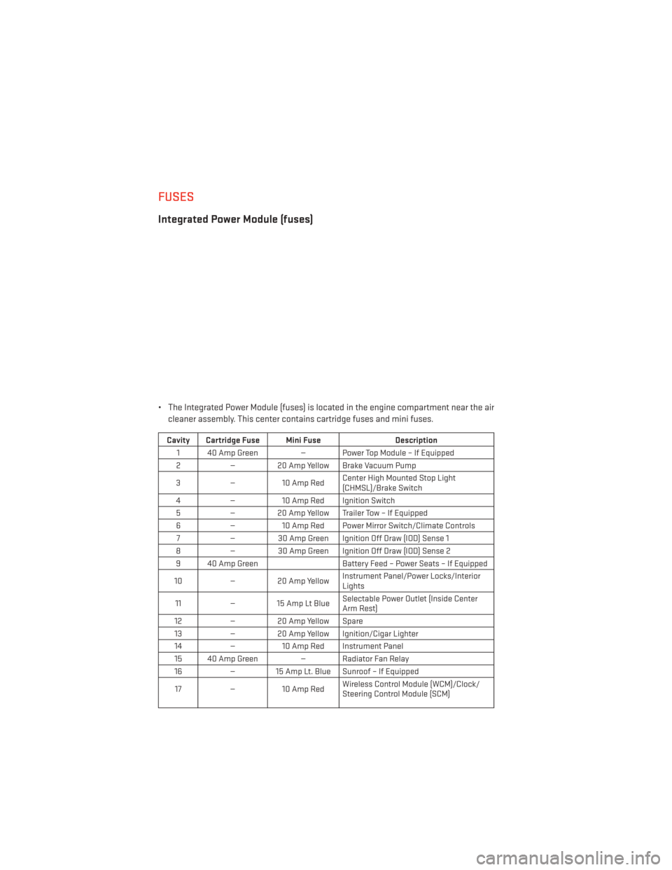
• The Integrated Power Module (fuses) is located in the engine compartment near the aircleaner assembly. This center contains cartridge fuses and mini fuses.
Cavity Cartridge Fuse Mini Fuse Description
1 40 Amp Green — Power Top Module – If Equipped
2 — 20 Amp Yellow Brake Vacuum Pump
3 —10 Amp Red Center High Mounted Stop Light
(CHMSL)/Brake Switch
4 —10 Amp Red Ignition Switch
5 — 20 Amp Yellow Trailer Tow – If Equipped
6 —10 Amp Red Power Mirror Switch/Climate Controls
7 — 30 Amp Green Ignition Off Draw (IOD) Sense 1
8 — 30 Amp Green Ignition Off Draw (IOD) Sense 2
9 40 Amp Green Battery Feed – Power Seats – If Equipped
10 — 20 Amp Yellow Instrument Panel/Power Locks/Interior
Lights
11 — 15 Amp Lt Blue Selectable Power Outlet (Inside Center
Arm Rest)
12 — 20 Amp Yellow Spare
13 — 20 Amp Yellow Ignition/Cigar Lighter
14 —10 Amp Red Instrument Panel
15 40 Amp Green — Radiator Fan Relay 16 — 15 Amp Lt. Blue Sunroof – If Equipped
17 —10 Amp Red Wireless Control Module (WCM)/Clock/
Steering Control Module (SCM)
MAINTAINING YOUR VEHICLE
104
Page 107 of 124
Cavity Cartridge Fuse Mini FuseDescription
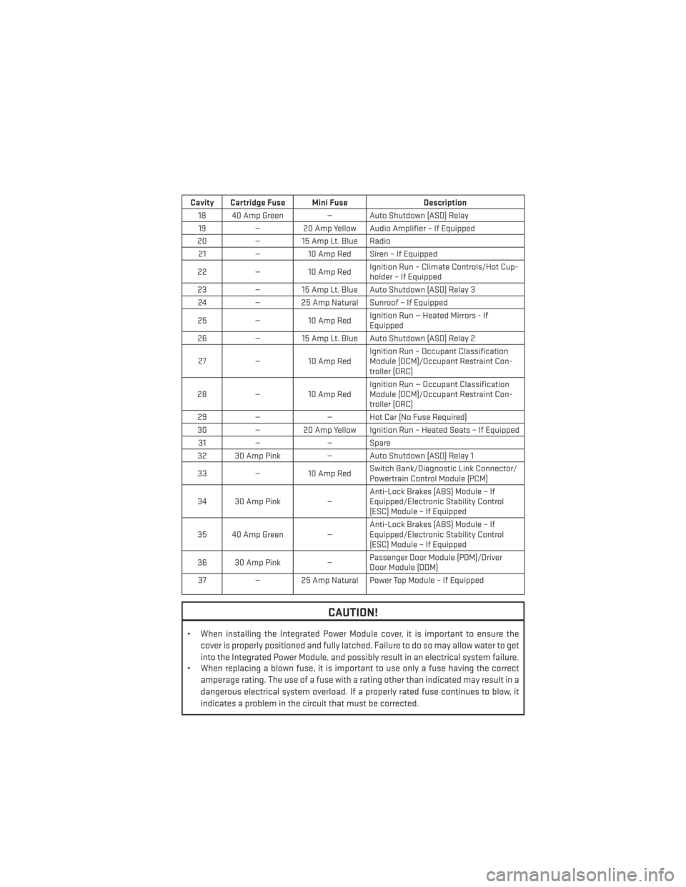
18 40 Amp Green — Auto Shutdown (ASD) Relay 19 — 20 Amp Yellow Audio Amplifier – If Equipped
20 — 15 Amp Lt. Blue Radio
21 —10 Amp Red Siren – If Equipped
22 —10 Amp Red Ignition Run – Climate Controls/Hot Cup-
holder – If Equipped
23 — 15 Amp Lt. Blue Auto Shutdown (ASD) Relay 3
24 — 25 Amp Natural Sunroof – If Equipped
25 —10 Amp Red Ignition Run — Heated Mirrors - If
Equipped
26 — 15 Amp Lt. Blue Auto Shutdown (ASD) Relay 2
27 —10 Amp Red Ignition Run – Occupant Classification
Module (OCM)/Occupant Restraint Con-
troller (ORC)
28 —10 Amp Red Ignition Run — Occupant Classification
Module (OCM)/Occupant Restraint Con-
troller (ORC)
29 — — Hot Car (No Fuse Required)
30 — 20 Amp Yellow Ignition Run – Heated Seats – If Equipped
31 — — Spare
32 30 Amp Pink — Auto Shutdown (ASD) Relay 1
33 —10 Amp Red Switch Bank/Diagnostic Link Connector/
Powertrain Control Module (PCM)
34 30 Amp Pink —Anti-Lock Brakes (ABS) Module – If
Equipped/Electronic Stability Control
(ESC) Module – If Equipped
35 40 Amp Green — Anti-Lock Brakes (ABS) Module – If
Equipped/Electronic Stability Control
(ESC) Module – If Equipped
36 30 Amp Pink —Passenger Door Module (PDM)/Driver
Door Module (DDM)
37 — 25 Amp Natural Power Top Module – If Equipped
CAUTION!
• When installing the Integrated Power Module cover, it is important to ensure the
cover is properly positioned and fully latched. Failure to do so may allow water to get
into the Integrated Power Module, and possibly result in an electrical system failure.
• When replacing a blown fuse, it is important to use only a fuse having the correct
amperage rating. The use of a fuse with a rating other than indicated may result in a
dangerous electrical system overload. If a properly rated fuse continues to blow, it
indicates a problem in the circuit that must be corrected.
MAINTAINING YOUR VEHICLE
105
Page 113 of 124
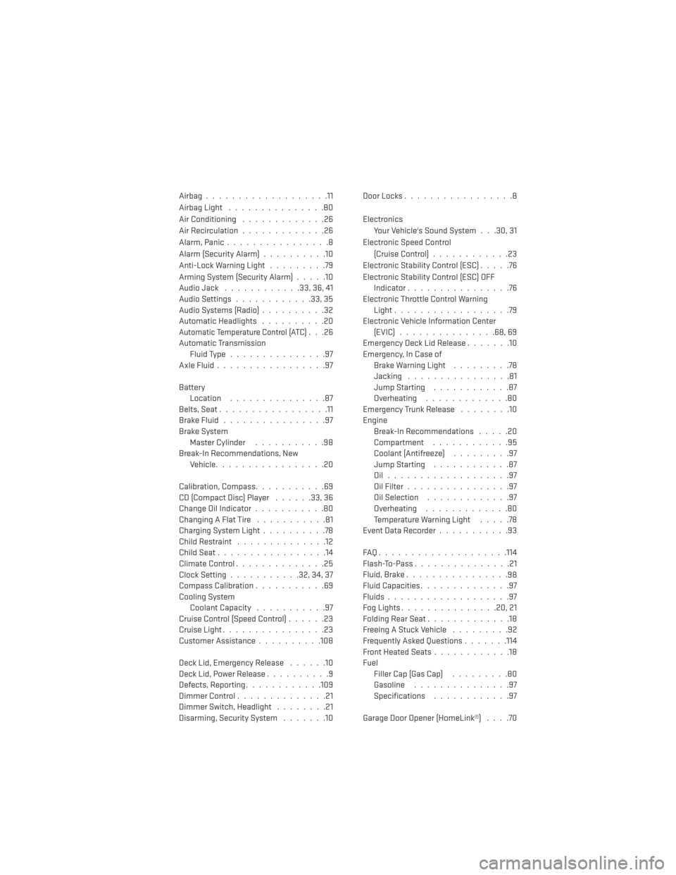
Airbag...................11
Airbag Light...............80
Air Conditioning .............26
Air Recirculation .............26
Alarm,Panic................8
Alarm (Security Alarm) ..........10
Anti-Lock Warning Light .........79
Arming System (Security Alarm) .....10
Audio Jack ............33,36,41
Audio Settings ............33,35
Audio Systems (Radio) ..........32
Automatic Headlights ..........20
Automatic Temperature Control (ATC). . .26
Automatic Transmission Fluid Type ...............97
AxleFluid.................97
Battery Location ...............87
Belts, Seat .................11
BrakeFluid................97
Brake System Master Cylinder ...........98
Break-In Recommendations, New Vehicle .................20
Calibration, Compass ...........69
CD (Compact Disc) Player ......33,36
Change Oil Indicator ...........80
Changing A Flat Tire ...........81
Charging System Light ..........78
Child Restraint ..............12
ChildSeat.................14
ClimateControl..............25
Clock Setting ...........32,34,37
Compass Calibration ...........69
Cooling System Coolant Capacity ...........97
Cruise Control (Speed Control) ......23
Cruise Light ................23
Customer Assistance ..........108
Deck Lid, Emergency Release ......10
Deck Lid, Power Release ..........9
Defects, Reporting ............109
Dimmer Control ..............21
Dimmer Switch, Headlight ........21
Disarming, Security System .......10DoorLocks.................8
Electronics
Your Vehicle's Sound System . . .30, 31
Electronic Speed Control (Cruise Control) ............23
Electronic Stability Control (ESC) .....76
Electronic Stability Control (ESC) OFF Indicator ................76
Electronic Throttle Control Warning Light ..................79
Electronic Vehicle Information Center (EVIC)...............68,69
Emergency Deck Lid Release .......10
Emergency, In Case of Brake Warning Light .........78
Jacking ................81
Jump Starting ............87
Overheating .............80
Emergency Trunk Release ........10
Engine Break-In Recommendations .....20
Compartment ............95
Coolant (Antifreeze) .........97
Jump Starting ............87
Oil...................97
Oil Filter ................97
Oil Selection .............97
Overheating .............80
Temperature Warning Light .....78
EventDataRecorder...........93
FAQ....................114
Flash-To-Pass ...............21
Fluid, Brake ................
98
Fluid Capacities ..............97
Fluids ...................97
FogLights...............20,21
Folding Rear Seat .............18
Freeing A Stuck Vehicle .........92
Frequently Asked Questions .......114
Front Heated Seats ............18
Fuel Filler Cap (Gas Cap) .........80
Gasoline ...............97
Specifications ............97
Garage Door Opener (HomeLink®) ....70
INDEX
111