lock DODGE CALIBER 2010 1.G Owner's Manual
[x] Cancel search | Manufacturer: DODGE, Model Year: 2010, Model line: CALIBER, Model: DODGE CALIBER 2010 1.GPages: 76, PDF Size: 12.18 MB
Page 42 of 76
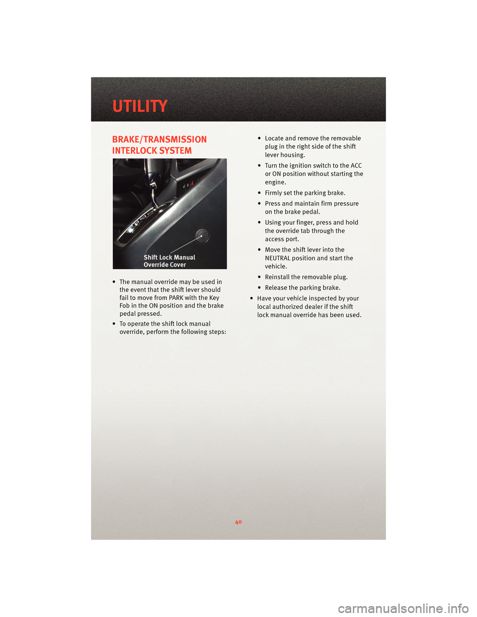
BRAKE/TRANSMISSION
INTERLOCK SYSTEM
• The manual override may be used inthe event that the shift lever should
fail to move from PARK with the Key
Fob in the ON position and the brake
pedal pressed.
• To operate the shift lock manual override, perform the following steps: • Locate and remove the removable
plug in the right side of the shift
lever housing.
• Turn the ignition switch to the ACC or ON position without starting the
engine.
• Firmly set the parking brake.
• Press and maintain firm pressure on the brake pedal.
• Using your finger, press and hold the override tab through the
access port.
• Move the shift lever into the NEUTRAL position and start the
vehicle.
• Reinstall the removable plug.
• Release the parking brake.
• Have your vehicle inspected by your local authorized dealer if the shift
lock manual override has been used.
UTILITY
40
Page 44 of 76
• Driving on under-inflated tires reduces yourvehicle’s fuel efficiency and tire tread life.
If a spare tire is in use on the vehicle, the TPMS light may turn on.
- Engine Temperature Warning Light
• This light warns of an overheated engine condition.
• If the light turns on and a warning chime sounds while driving, safely pull over and stop the vehicle. If the A/C system is on, t urn it off. Also, shiftthe transmission into
NEUTRAL and idle the vehicle. If the temperat ure reading does not return to normal,
turn the engine off immediately.
• We recommend that you do not operate the vehicle or engine damage will occur. Have the vehicle serviced immediately.
WARNING!
A hot engine cooling system is dangero us. You or others could be badly burned by
steam or boiling coolant. You may want to call an authorized dealership for service if
your vehicle overheats.
- Brake Warning Light
• The Brake Warning light illuminates when there is either a system malfunction or the
parking brake is applied. If the light is on and the parking brake is not applied, it
indicates a possible brake hydraulic malfunction, brake booster problem or an
Anti-Lock Brake System problem.
• We recommend you drive to the nearest service center and have the vehicle serviced immediately.
WARNING!
Driving a vehicle with the red brake light on is dangerous. Part of the brake system
may have failed. It will take longer to stop the vehicle. You could have an accident.
Have the vehicle checked immediately.
- Malfunction Indicator Light (MIL)
• Certain conditions, such as a loose or m issing gas cap,poor fuel quality, etc., may
illuminate the MIL after engine start. The vehicle should be serviced if the light stays
on through several typical driving cycles. In most situations, the vehicle will drive
normally and not require towing.
• If the MIL flashes when the engine is running, serious conditions may exist that could lead to immediate loss of power or severe catalytic converter damage. We recommend
you do not operate the vehicle. Hav e the vehicle serviced immediately.
WHAT TO DO IN EMERGENCIES
42
Page 45 of 76
- Charging System Light
• This light shows the status of the electrical charging system. If the charging system
light remains on, it means that the vehicle is experiencing a problem with the charging
system.
• We recommend you do not continue driving if the charging system light is on. Have the vehicle serviced immediately.
- Oil Pressure Warning Light
• This light indicates low engine oil pressure. If the light turns on while driving, stop thevehicle and shut off the engine as soon as possible. A chime will sound for four
minutes when this light turns on.
• We recommend you do not operate the vehicle or engine damage will occur. Have the vehicle serviced immediately.
- Anti-Lock Brake (ABS) Light
• This light monitors the Anti-Lock Brake System (ABS).
• If the light is not on during starting, stays on, or turns on while driving, we recommendyou drive to the nearest service center and have the vehicle serviced immediately.
- Electronic Throttle Control (ETC) Light
• This light informs you of a problem with the Electronic Throttle Control (ETC) system.
• If a problem is detected, the light will come on while the engine is running. Cycle theignition when the vehicle has completely stopped and the shift lever is placed in the
PARK position; the light should turn off.
• If the light remains lit with the engine running, your vehicle will usually be drivable; however, see an authorized dealer for service immediately. If the light is flashing
when the engine is running, immediate servi ce is required and you may experience
reduced performance, an el evated/rough idle or engine stall and your vehicle may
require towing.
- Airbag Warning Light
• If the light is not on during starting, stays on, or turns on while driving, we recommend you drive to the nearest service center and have the vehicle serviced immediately.
- Transaxle Temperature Warning Light
• This light indicates that ther e is excessive transmission fluid temperat ure that might
occur with severe usage such as trailer towing. If this light turns on, you will
experience reduced vehicle performance unti l the automatic transaxle cools down. If
the overheating continues, stop the vehicle and run the engine at idle, with the
transmission in NEUTRAL, until the light turns off. Once the light turns off, you may
continue to drive normally.
43
WHAT TO DO IN EMERGENCIES
Page 46 of 76
Fuel Cap/Loose Gas Cap Message
• If a “gas cap” message (shown as gASCAP) appears, tighten the gas cap until a“clicking” sound is heard.
• Press the odometer reset button, located belo w the tachometer, to turn the message
off.
• If the message continues to appear for mor e than three days after tightening the gas
cap, see your authorized dealer.
Oil Change Indicator
Message
• If an “oil change” message (shown as CHAngE OIL) appears and a single chime
sounds, it is time for your next required oil change.
Resetting The Light After Servicing
• Turn the ignition switch to the ON/RUN position (do not start engine).
• Fully depress the accelerator pedal three times within 10 seconds.
• Turn the ignition switch to the OFF/LOCK position.
IF YOUR ENGINE OVERHEATS
• In any of the following situations, you c an reduce the potential for overheating by
taking the appropriate action.
• On the highways — slow down.
• In city traffic — while stopped, shift tran smission intoNEUTRAL, but do not increase
engine idle speed.
NOTE: There are steps that you can take to slow down an impending overheat
condition:
• If your air conditioner (A/C) is on, turn it off. The A/C system adds heat to the engine cooling system and turning the A/C off can help remove this heat.
• You can also turn the Temperature Control to maximum heat, the Mode Control to floor and the Fan Control to high. This allows the heater core to act as a supplement to the
radiator and aids in removing heat from the engine cooling system.
• If the temperature reading does not re turn to normal, turn the engine off immediately.
• We recommend that you do not operate the vehicle or engine damage will occur. Have the vehicle serviced immediately.
WHAT TO DO IN EMERGENCIES
44
Page 49 of 76
WARNING!
Do not attempt to change a tire on the side of the vehicle close to moving traffic. Pull
far enough off the road to avoid being hit when operating the jack or changing the
wheel.
• Set the parking brake and shift the aut omatic transmission into P ARK, or a manual
transmission into REVERSE.
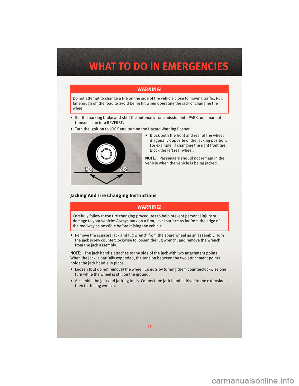
• Turn the ignition to LOCK and turn on the Hazard Warning flasher. • Block both the front and rear of the wheeldiagonally opposite of the jacking position.
For example, if changing the right front tire,
block the left rear wheel.
NOTE: Passengers should not remain in the
vehicle when the vehicle is being jacked.
Jacking And Tire Changing Instructions
WARNING!
Carefully follow these tire changing p rocedures to help prevent personal injury or
damage to your vehicle: Always park on a firm, level surface as far from the edge of
the roadway as possible before raising the vehicle.
• Remove the scissors jack and lug wrench from the spare wheel as an assembly. Turn the jack screw countercloc kwise to loosen the lug wrench, and remove the wrench
from the jack assembly.
NOTE: The jack handle attaches to the side of the jack with two attachment points.
When the jack is partially expanded, the tension between the two attachment points
holds the jack handle in place.
• Loosen (but do not remove) the wheel lug nuts by turning them counterclockwise one
turn while the wheel is still on the ground.
• Assemble the jack and jacking tools. Connect the jack handle driver to the extension, then to the lug wrench.
47
WHAT TO DO IN EMERGENCIES
Page 50 of 76
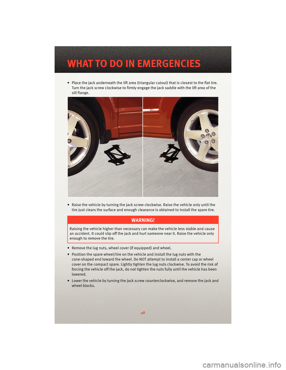
• Place the jack underneath the lift area (triangular cutout) that is closest to the flat tire.Turn the jack screw clockwise to firmly engage the jack saddle with the lift area of the
sill flange.
• Raise the vehicle by turning the jack screw clockwise. Raise the vehicle only until the tire just clears the surface and enough clearance is obtained to install the spare tire.
WARNING!
Raising the vehicle higher than necessary can make the vehicle less stable and cause
an accident. It could slip off the jack and hurt someone near it. Raise the vehicle only
enough to remove the tire.
• Remove the lug nuts, wheel cover (if equipped) and wheel.
• Position the spare wheel/tire on the vehicle and install the lug nuts with the cone-shaped end toward the wheel. Do NOT attempt to install a center cap or wheel
cover on the compact spare. Lightly tighten the lug nuts clockwise. To avoid the risk of
forcing the vehicle off the jack, do not tighten the nuts fully until the vehicle has been
lowered.
• Lower the vehicle by turning the jack screw counterclockwise, and remove the jack and wheel blocks.
WHAT TO DO IN EMERGENCIES
48
Page 53 of 76
• Set the parking brake, shift the automatic transmission into PARK and turn the ignition
to LOCK.
• Turn off the heater, radio, and all unnecessary electrical accessories.
• If using another vehicle to jump-start the battery, park the vehicle within the jumper cables reach, set the parking brake and make sure the ignition is OFF.
WARNING!
Do not allow vehicles to touch each other as this could establish a ground connection
and personal injury could result.
Jump-Starting Procedure
WARNING!
Failure to follow this procedure could result in personal injury or property damage due
to battery explosion.
CAUTION!
Failure to follow these procedures could result in damage to the charging system of
the booster vehicle or the discharged vehicle.
• Connect the positive (+)end of the jumper cable to the positive (+)post of the
discharged vehicle.
• Connect the opposite end of the positive (+)jumper cable to the positive (+)post of
the booster battery.
• Connect the negative end (-)of the jumper cable to the negative (-)post of the booster
battery.
• Connect the opposite end of the negative (-)jumper cable to a good engine ground
(exposed metal part of the discharged vehicle’s engine) away from the battery and the
fuel injection system.
WARNING!
Do not connect the cable to the negative post (-)of the discharged battery. The
resulting electrical spark could cause the battery to explode and could result in
personal injury.
51
WHAT TO DO IN EMERGENCIES
Page 58 of 76
OPENING THE HOOD
• Pull the release lever located belowthe instrument panel and in front of the driver’s
door.
• Raise the hood and locate the safety latch, in the middle of the hood opening.
• Move the safety latch while lifting the hood at the same time.
• Insert the support rod into the slot on the hood.
• To close the hood, remove the support rod and place it in the retaining clip, then lower the hood slowly.
WARNING!
Be sure the hood is fully latched before driving your vehicle. If the hood is not fully
latched, it could open when the vehicle is in motion and block your vision. Failure to
follow this warning could result in serious injury or death.
MAINTAINING YOUR VEHICLE
56
Page 64 of 76
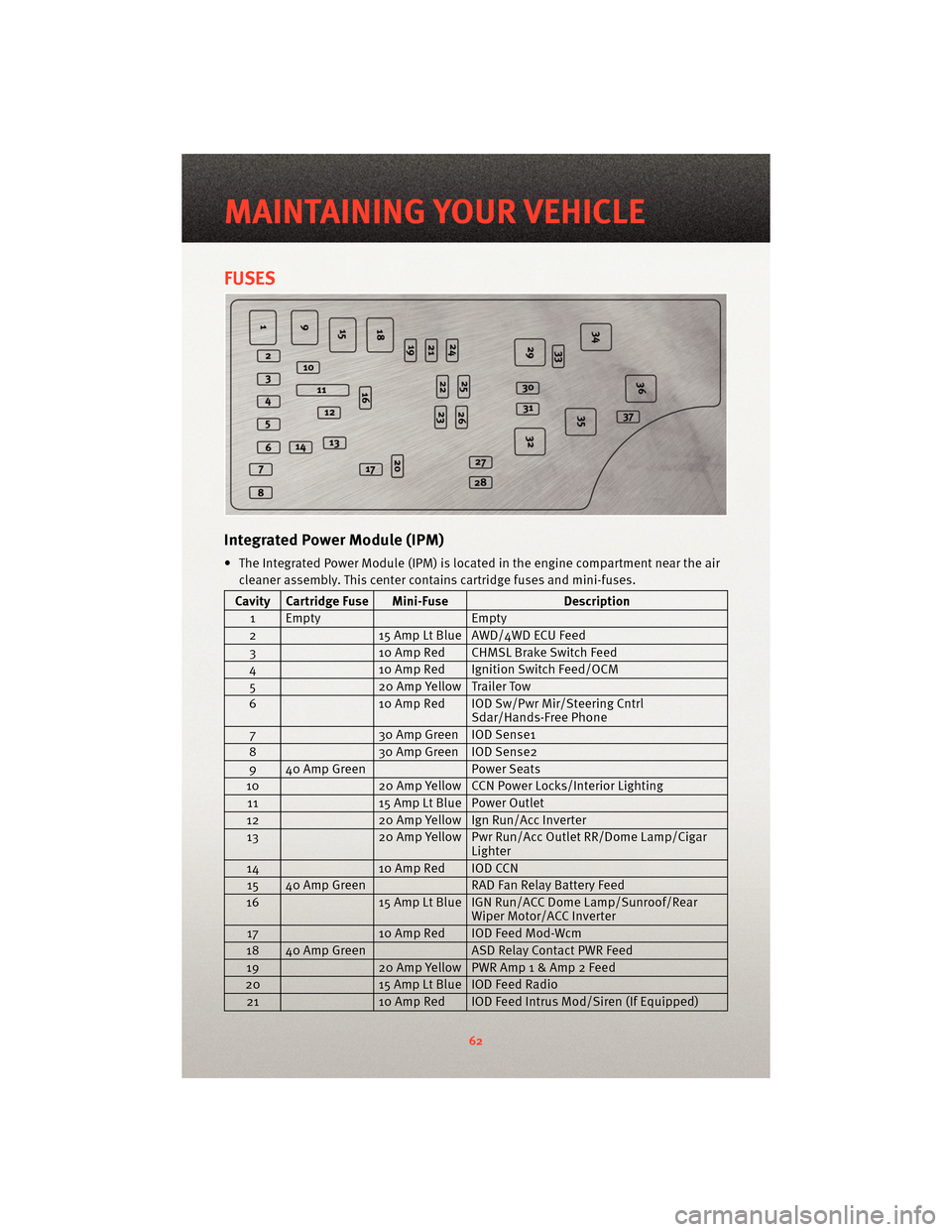
FUSES
Integrated Power Module (IPM)
• The Integrated Power Module (IPM) is located in the engine compartment near the aircleaner assembly. This center contains cartridge fuses and mini-fuses.
Cavity Cartridge Fuse Mini-Fuse Description
1 Empty Empty
2 15 Amp Lt Blue AWD/4WD ECU Feed
3 10 Amp Red CHMSL Brake Switch Feed
4 10 Amp Red Ignition Switch Feed/OCM
5 20 Amp Yellow Trailer Tow
6 10 Amp Red IOD Sw/Pwr Mir/Steering Cntrl
Sdar/Hands-Free Phone
7 30 Amp Green IOD Sense1
8 30 Amp Green IOD Sense2
9 40 Amp Green Power Seats
10 20 Amp Yellow CCN Power Locks/Interior Lighting
11 15 Amp Lt Blue Power Outlet
12 20 Amp Yellow Ign Run/Acc Inverter
13 20 Amp Yellow Pwr Run/Acc Outlet RR/Dome Lamp/Cigar
Lighter
14 10 Amp Red IOD CCN
15 40 Amp Green RAD Fan Relay Battery Feed
16 15 Amp Lt Blue IGN Run/ACC Dome Lamp/Sunroof/Rear
Wiper Motor/ACC Inverter
17 10 Amp Red IOD Feed Mod-Wcm
18 40 Amp Green ASD Relay Contact PWR Feed
19 20 Amp Yellow PWR Amp 1 & Amp 2 Feed
20 15 Amp Lt Blue IOD Feed Radio
21 10 Amp Red IOD Feed Intrus Mod/Siren (If Equipped)
MAINTAINING YOUR VEHICLE
62