lock DODGE CALIBER 2011 1.G Owner's Manual
[x] Cancel search | Manufacturer: DODGE, Model Year: 2011, Model line: CALIBER, Model: DODGE CALIBER 2011 1.GPages: 80, PDF Size: 3.66 MB
Page 49 of 80
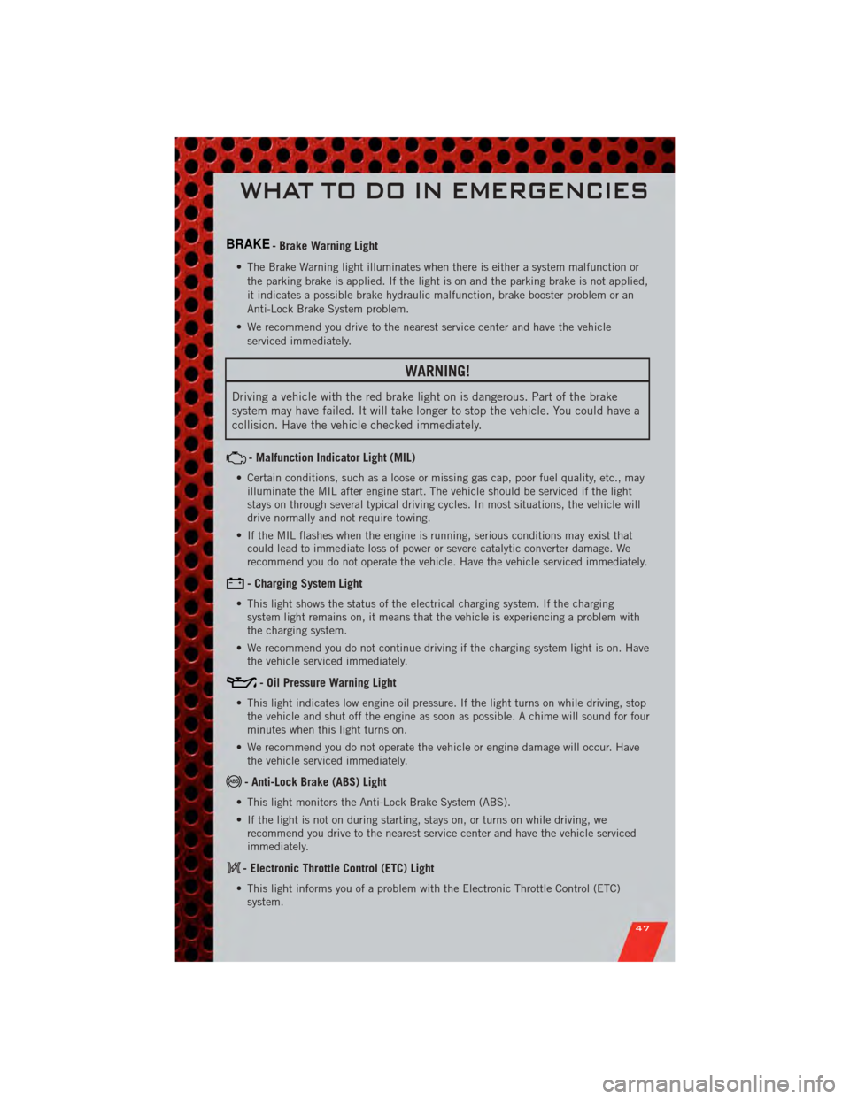
BRAKE- Brake Warning Light
• The Brake Warning light illuminates when there is either a system malfunction orthe parking brake is applied. If the light is on and the parking brake is not applied,
it indicates a possible brake hydraulic malfunction, brake booster problem or an
Anti-Lock Brake System problem.
• We recommend you drive to the nearest service center and have the vehicle serviced immediately.
WARNING!
Driving a vehicle with the red brake light on is dangerous. Part of the brake
system may have failed. It will take longer to stop the vehicle. You could have a
collision. Have the vehicle checked immediately.
- Malfunction Indicator Light (MIL)
• Certain conditions, such as a loose or missing gas cap, poor fuel quality, etc., mayilluminate the MIL after engine start. The vehicle should be serviced if the light
stays on through several typical driving cycles. In most situations, the vehicle will
drive normally and not require towing.
• If the MIL flashes when the engine is running, serious conditions may exist that could lead to immediate loss of power or severe catalytic converter damage. We
recommend you do not operate the vehicle. Have the vehicle serviced immediately.
- Charging System Light
• This light shows the status of the electrical charging system. If the chargingsystem light remains on, it means that the vehicle is experiencing a problem with
the charging system.
• We recommend you do not continue driving if the charging system light is on. Have the vehicle serviced immediately.
- Oil Pressure Warning Light
• This light indicates low engine oil pressure. If the light turns on while driving, stopthe vehicle and shut off the engine as soon as possible. A chime will sound for four
minutes when this light turns on.
• We recommend you do not operate the vehicle or engine damage will occur. Have the vehicle serviced immediately.
- Anti-Lock Brake (ABS) Light
• This light monitors the Anti-Lock Brake System (ABS).
• If the light is not on during starting, stays on, or turns on while driving, werecommend you drive to the nearest service center and have the vehicle serviced
immediately.
- Electronic Throttle Control (ETC) Light
• This light informs you of a problem with the Electronic Throttle Control (ETC)system.
WHAT TO DO IN EMERGENCIES
47
Page 50 of 80
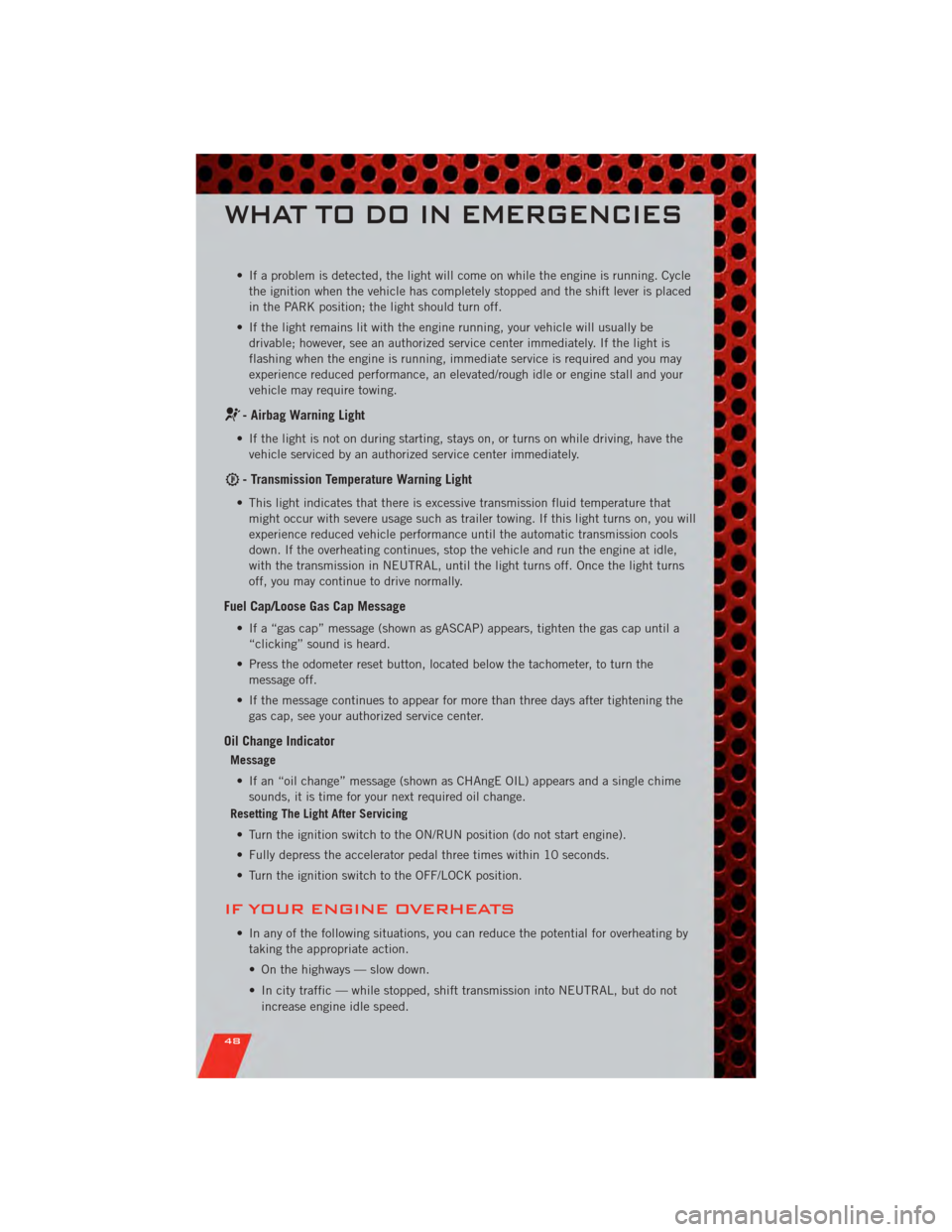
• If a problem is detected, the light will come on while the engine is running. Cyclethe ignition when the vehicle has completely stopped and the shift lever is placed
in the PARK position; the light should turn off.
• If the light remains lit with the engine running, your vehicle will usually be drivable; however, see an authorized service center immediately. If the light is
flashing when the engine is running, immediate service is required and you may
experience reduced performance, an elevated/rough idle or engine stall and your
vehicle may require towing.
- Airbag Warning Light
• If the light is not on during starting, stays on, or turns on while driving, have thevehicle serviced by an authorized service center immediately.
- Transmission Temperature Warning Light
• This light indicates that there is excessive transmission fluid temperature thatmight occur with severe usage such as trailer towing. If this light turns on, you will
experience reduced vehicle performance until the automatic transmission cools
down. If the overheating continues, stop the vehicle and run the engine at idle,
with the transmission in NEUTRAL, until the light turns off. Once the light turns
off, you may continue to drive normally.
Fuel Cap/Loose Gas Cap Message
• If a “gas cap” message (shown as gASCAP) appears, tighten the gas cap until a“clicking” sound is heard.
• Press the odometer reset button, located below the tachometer, to turn the message off.
• If the message continues to appear for more than three days after tightening the gas cap, see your authorized service center.
Oil Change Indicator
Message
• If an “oil change” message (shown as CHAngE OIL) appears and a single chime sounds, it is time for your next required oil change.
Resetting The Light After Servicing
• Turn the ignition switch to the ON/RUN position (do not start engine).
• Fully depress the accelerator pedal three times within 10 seconds.
• Turn the ignition switch to the OFF/LOCK position.
IF YOUR ENGINE OVERHEATS
• In any of the following situations, you can reduce the potential for overheating by taking the appropriate action.
• On the highways — slow down.
• In city traffic — while stopped, shift transmission into NEUTRAL, but do not
increase engine idle speed.
WHAT TO DO IN EMERGENCIES
48
Page 52 of 80
JACKING AND TIRE CHANGING
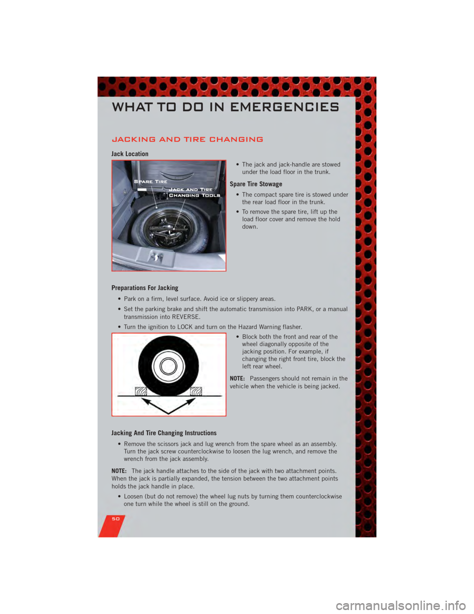
Jack Location
• The jack and jack-handle are stowedunder the load floor in the trunk.
Spare Tire Stowage
• The compact spare tire is stowed underthe rear load floor in the trunk.
• To remove the spare tire, lift up the load floor cover and remove the hold
down.
Preparations For Jacking
• Park on a firm, level surface. Avoid ice or slippery areas.
• Set the parking brake and shift the automatic transmission into PARK, or a manual
transmission into REVERSE.
• Turn the ignition to LOCK and turn on the Hazard Warning flasher. • Block both the front and rear of thewheel diagonally opposite of the
jacking position. For example, if
changing the right front tire, block the
left rear wheel.
NOTE: Passengers should not remain in the
vehicle when the vehicle is being jacked.
Jacking And Tire Changing Instructions
• Remove the scissors jack and lug wrench from the spare wheel as an assembly. Turn the jack screw counterclockwise to loosen the lug wrench, and remove the
wrench from the jack assembly.
NOTE: The jack handle attaches to the side of the jack with two attachment points.
When the jack is partially expanded, the tension between the two attachment points
holds the jack handle in place.
• Loosen (but do not remove) the wheel lug nuts by turning them counterclockwiseone turn while the wheel is still on the ground.
WHAT TO DO IN EMERGENCIES
50
Page 53 of 80
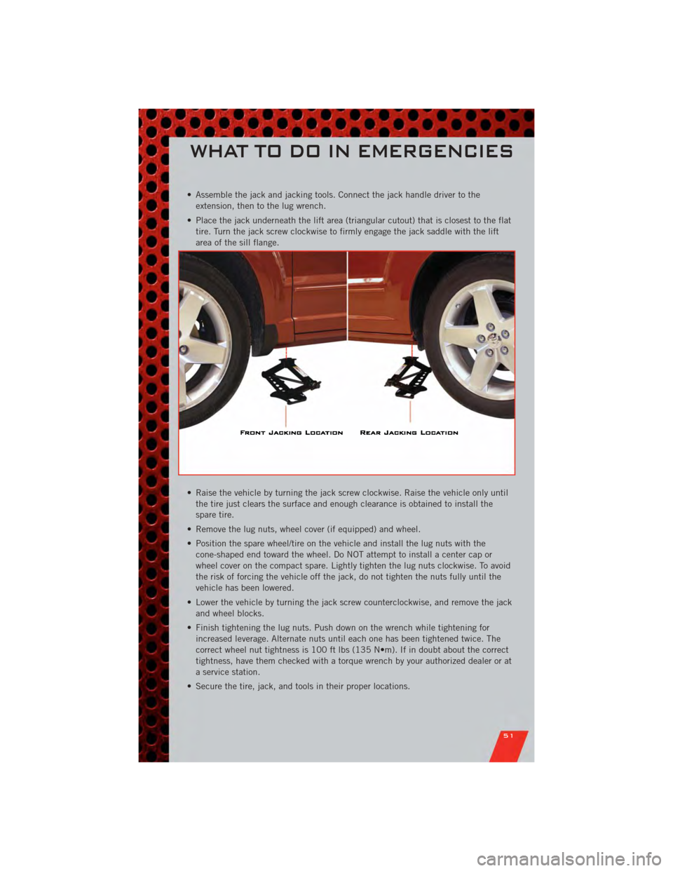
• Assemble the jack and jacking tools. Connect the jack handle driver to theextension, then to the lug wrench.
• Place the jack underneath the lift area (triangular cutout) that is closest to the flat tire. Turn the jack screw clockwise to firmly engage the jack saddle with the lift
area of the sill flange.
• Raise the vehicle by turning the jack screw clockwise. Raise the vehicle only until the tire just clears the surface and enough clearance is obtained to install the
spare tire.
• Remove the lug nuts, wheel cover (if equipped) and wheel.
• Position the spare wheel/tire on the vehicle and install the lug nuts with the cone-shaped end toward the wheel. Do NOT attempt to install a center cap or
wheel cover on the compact spare. Lightly tighten the lug nuts clockwise. To avoid
the risk of forcing the vehicle off the jack, do not tighten the nuts fully until the
vehicle has been lowered.
• Lower the vehicle by turning the jack screw counterclockwise, and remove the jack and wheel blocks.
• Finish tightening the lug nuts. Push down on the wrench while tightening for increased leverage. Alternate nuts until each one has been tightened twice. The
correct wheel nut tightness is 100 ft lbs (135 N•m). If in doubt about the correct
tightness, have them checked with a torque wrench by your authorized dealer or at
a service station.
• Secure the tire, jack, and tools in their proper locations.
WHAT TO DO IN EMERGENCIES
51
Page 55 of 80
Preparations for Jump-Start
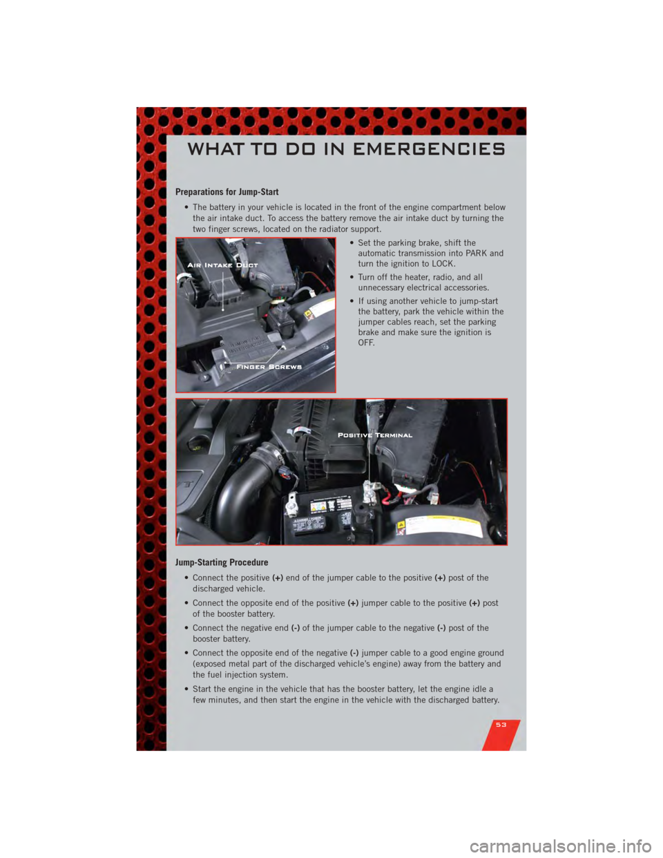
• The battery in your vehicle is located in the front of the engine compartment belowthe air intake duct. To access the battery remove the air intake duct by turning the
two finger screws, located on the radiator support.
• Set the parking brake, shift theautomatic transmission into PARK and
turn the ignition to LOCK.
• Turn off the heater, radio, and all unnecessary electrical accessories.
• If using another vehicle to jump-start the battery, park the vehicle within the
jumper cables reach, set the parking
brake and make sure the ignition is
OFF.
Jump-Starting Procedure
• Connect the positive (+)end of the jumper cable to the positive (+)post of the
discharged vehicle.
• Connect the opposite end of the positive (+)jumper cable to the positive (+)post
of the booster battery.
• Connect the negative end (-)of the jumper cable to the negative (-)post of the
booster battery.
• Connect the opposite end of the negative (-)jumper cable to a good engine ground
(exposed metal part of the discharged vehicle’s engine) away from the battery and
the fuel injection system.
• Start the engine in the vehicle that has the booster battery, let the engine idle a few minutes, and then start the engine in the vehicle with the discharged battery.
WHAT TO DO IN EMERGENCIES
53
Page 61 of 80
OPENING THE HOOD
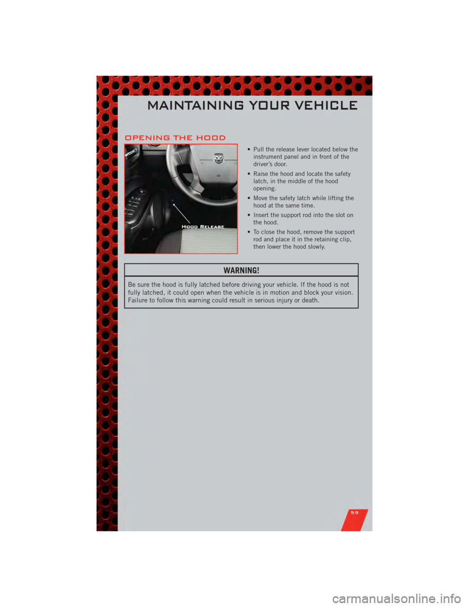
• Pull the release lever located below theinstrument panel and in front of the
driver’s door.
• Raise the hood and locate the safety latch, in the middle of the hood
opening.
• Move the safety latch while lifting the hood at the same time.
• Insert the support rod into the slot on the hood.
• To close the hood, remove the support rod and place it in the retaining clip,
then lower the hood slowly.
WARNING!
Be sure the hood is fully latched before driving your vehicle. If the hood is not
fully latched, it could open when the vehicle is in motion and block your vision.
Failure to follow this warning could result in serious injury or death.
MAINTAINING YOUR VEHICLE
59
Page 68 of 80
FUSES
Integrated Power Module (fuses)
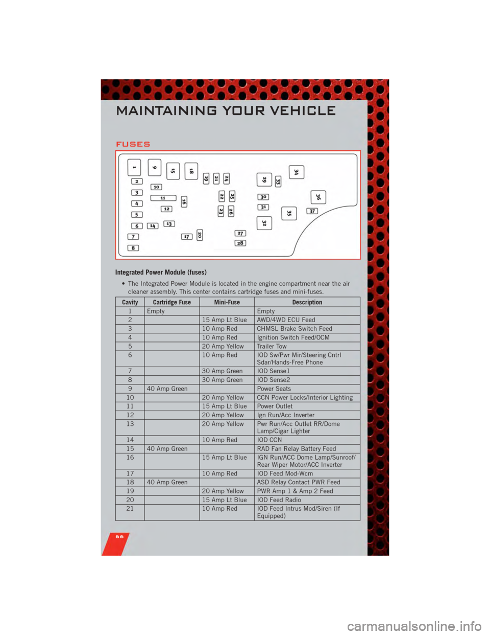
• The Integrated Power Module is located in the engine compartment near the aircleaner assembly. This center contains cartridge fuses and mini-fuses.
Cavity Cartridge Fuse Mini-Fuse Description
1 Empty Empty
2 15 Amp Lt Blue AWD/4WD ECU Feed
3 10 Amp Red CHMSL Brake Switch Feed
4 10 Amp Red Ignition Switch Feed/OCM
5 20 Amp Yellow Trailer Tow
6 10 Amp Red IOD Sw/Pwr Mir/Steering Cntrl
Sdar/Hands-Free Phone
7 30 Amp Green IOD Sense1
8 30 Amp Green IOD Sense2
9 40 Amp Green Power Seats
10 20 Amp Yellow CCN Power Locks/Interior Lighting
11 15 Amp Lt Blue Power Outlet
12 20 Amp Yellow Ign Run/Acc Inverter
13 20 Amp Yellow Pwr Run/Acc Outlet RR/Dome
Lamp/Cigar Lighter
14 10 Amp Red IOD CCN
15 40 Amp Green RAD Fan Relay Battery Feed
16 15 Amp Lt Blue IGN Run/ACC Dome Lamp/Sunroof/
Rear Wiper Motor/ACC Inverter
17 10 Amp Red IOD Feed Mod-Wcm
18 40 Amp Green ASD Relay Contact PWR Feed
19 20 Amp Yellow PWR Am p1&Amp2Feed
20 15 Amp Lt Blue IOD Feed Radio
21 10 Amp Red IOD Feed Intrus Mod/Siren (If
Equipped)
MAINTAINING YOUR VEHICLE
66
Page 74 of 80
Air Conditioning.......... 20,21
Airbag .................. 10
AirbagLight ............... 48
Alarm, Panic ............... 8
Anti-Lock Brake System (ABS) .... 47
Arming Theft System
(Security Alarm) ............. 9
Audio Jack ............... 29
Audio Settings ............. 27
Automatic Temperature Control
(ATC) ................... 21
Automatic Transmission Autostick ............... 20
FluidType .............. 62
Overheating ............. 49
AxleFluid ................ 62
Battery Charging System Light ....... 47
Belts, Seat ................ 9
BrakeFluid ............... 62
Brake System WarningLight ............ 47
Bulb Replacement ........... 68
Calibration, Compass ......... 38
Change Oil Indicator .......... 48
Charging System Light ......... 47
Check Engine Light (Malfunction
Indicator Light) ............. 47
Child Restraint ............. 11
Child Restraint Tether Anchors .... 11
ClimateControl ........... 20,21
Clock Setting ............ 28,30
Compass Calibration .......... 38
Cooling System Coolant Capacity ........... 62
Cruise Control (Speed Control) .... 19
CruiseLight ............... 19
Customer Assistance .......... 69
Defects, Reporting ........... 70
Defroster, Rear Window ........ 20
Defroster, Windshield ......... 20
Dimmer Control ............. 17
Dimmer Switch, Headlight ...... 17
Disarming, Theft System ........ 9Driver Cockpit
.............. 4
ECO ................... 38
Electronic Speed Control
(CruiseControl) ............. 19
Electronic Stability Program (ESP) . . 45
Electronic Throttle Control Warning
Light ................... 47
Electronic Vehicle Information Center
(EVIC) ................ 37,38
Electronics Your Vehicle's Sound System .... 24
Engine Compartment ............. 60
Malfunction Indicator
(CheckEngine) ............ 47
Oil Selection ............. 62
Overheating ............. 48
EventDataRecorder .......... 58
Exterior Lights ............. 68
Flash-To-Pass .............. 17
Fluid Capacities ............ 62
Fluids .................. 62
FogLights ................ 17
Folding Front Passenger Seat ..... 14
FoldingRearSeat ........... 15
Freeing A Stuck Vehicle ........ 57
Front Heated Seats ........... 15
Fuel Filler Cap (Gas Cap) ......... 48
Specifications ............
6
2
Fuses .................. 66
Garage Door Opener (HomeLink
®)..40
Gas Cap (Fuel Filler Cap) ....... 48
Hard Disk Drive ............. 30
Headlights ............... 17 Dimmer Switch ........... 17
HighBeam .............. 17
Heated Seats .............. 15
High Beam/Low Beam Select
(Dimmer) Switch ............ 17
HomeLink
®(Garage Door Opener)
Transmitter ............... 40
Hood Release .............. 59
INDEX
72
Page 75 of 80
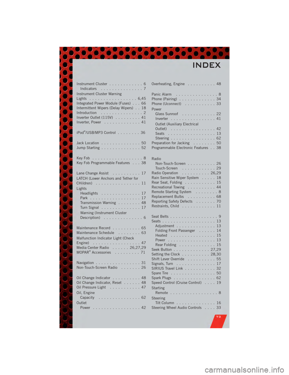
Instrument Cluster............ 6
Indicators ............... 7
Instrument Cluster Warning
Lights ................. 6,45
Integrated Power Module (Fuses) . . . 66
Intermittent Wipers (Delay Wipers) . . 18
Introduction ............... 2
Inverter Outlet (115V) ......... 41
Inverter, Power ............. 41
iPod
®/USB/MP3 Control ........ 36
Jack Location .............. 50
Jump Starting .............. 52
KeyFob .................. 8
Key Fob Programmable Features . . . 38
Lane Change Assist .......... 17
LATCH (Lower Anchors and Tether for
CHildren) ................ 11
Lights Headlights .............. 17
Park .................. 17
Transmission Warning ........ 48
TurnSignal .............. 17
Warning (Instrument Cluster
Description) .............. 6
Maintenance Record .......... 65
MaintenanceSchedule ........ 63
Malfunction Indicator Light (Check
Engine) ................. 47
MediaCenterRadio ...... 26,27,29
MOPAR
®Accessories ......... 71
Navigation ................ 31
Non-Touch-Screen Radio ....... 26
OilChangeIndicator .......... 48
Oil Change Indicator, Reset ...... 48
Oil Pressure Light ........... 47
Oil, Engine Capacity ............... 62
Outlet Power ................. 42 Overheating, Engine
.......... 48
Panic Alarm ............... 8
Phone (Pairing) ............. 34
Phone (Uconnect) ........... 33
Power Glass Sunroof ............ 22
Inverter ................ 41
Outlet (Auxiliary Electrical
Outlet) ................ 42
Seats ................. 13
Steering ................ 62
Preparation for Jacking ........ 50
Programmable Electronic Features . . 38
Radio Non-Touch-Screen .......... 26
Touch-Screen ............ 29
Radio Operation .......... 26,29
Rain Sensitive Wiper System ..... 18
Rear Seat, Folding ........... 15
Recreational Towing .......... 44
Remote Starting System ........ 8
ReplacementBulbs .......... 68
Reporting Safety Defects ....... 70
Restraints, Child ............ 11
Seat Belts ................. 9
Seats ................... 13
Adjustment .............. 13
Folding Front Passenger ...... 14
Heated ................ 15
Power ................. 13
RearFolding ............. 15
Seek Button ............. 27,29
Setting the Clock .......... 28,30
Shift Lever Override .......... 55
Signals, Turn .............. 17
SIRIUS Travel Link ........... 32
SpareTire ................ 50
SparkPlugs ............... 62
Speed Control (Cruise Control) .... 19
Starting Remote ................. 8
Steering TiltColumn .............. 16
Steering Wheel Audio Controls .... 33
INDEX
73