wheel DODGE CALIBER 2011 1.G User Guide
[x] Cancel search | Manufacturer: DODGE, Model Year: 2011, Model line: CALIBER, Model: DODGE CALIBER 2011 1.GPages: 80, PDF Size: 3.66 MB
Page 3 of 80
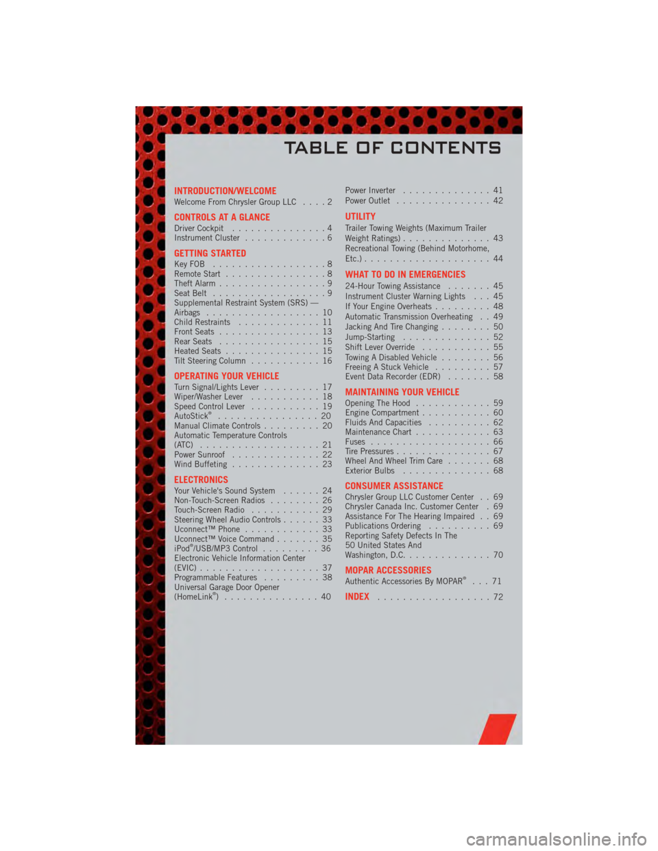
INTRODUCTION/WELCOMEWelcome From Chrysler Group LLC....2
CONTROLS AT A GLANCEDriver Cockpit...............4
Instrument Cluster .............6
GETTING STARTEDKeyFOB ..................8
Remote Start................8
Theft Alarm .................9
Seat Belt ..................9
Supplemental Restraint System (SRS) —
Airbags ..................10
Child Restraints .............11
Front Seats ................13
Rear Seats ................15
Heated Seats ...............15
Tilt Steering Column ...........16
OPERATING YOUR VEHICLETurn Signal/Lights Lever .........17
Wiper/Washer Lever ...........18
Speed Control Lever ...........19
AutoStick
®................20
Manual Climate Controls .........20
Automatic Temperature Controls
(ATC) ...................21
Power Sunroof ..............22
Wind Buffeting ..............23
ELECTRONICSYour Vehicle's Sound System ......24
Non-Touch-Screen Radios ........26
Touch-Screen Radio ...........29
Steering Wheel Audio Controls ......33
Uconnect™ Phone ............33
Uconnect™ Voice Command .......35
iPod
®/USB/MP3 Control .........36
Electronic Vehicle Information Center
(EVIC) ...................37
Programmable Features .........38
Universal Garage Door Opener
(HomeLink
®) ...............40 Power Inverter
..............41
Power Outlet ...............42
UTILITY
Trailer Towing Weights (Maximum Trailer
Weight Ratings) ..............43
Recreational Towing (Behind Motorhome,
Etc.) ....................44
WHAT TO DO IN EMERGENCIES
24-Hour Towing Assistance .......45
Instrument Cluster Warning Lights . . . 45
If Your Engine Overheats .........48
Automatic Transmission Overheating . . 49
Jacking And Tire Changing ........50
Jump-Starting ..............52
Shift Lever Override ...........55
Towing A Disabled Vehicle ........56
Freeing A Stuck Vehicle .........57
Event Data Recorder (EDR) .......58
MAINTAINING YOUR VEHICLEOpening The Hood............59
Engine Compartment ...........60
Fluids And Capacities ..........62
Maintenance Chart ............63
Fuses ...................66
Tire Pressures ...............67
Wheel And Wheel Trim Care .......68
Exterior Bulbs ..............68
CONSUMER ASSISTANCEChrysler Group LLC Customer Center . . 69
Chrysler Canada Inc. Customer Center . 69
Assistance For The Hearing Impaired . . 69
Publications Ordering ..........69
Reporting Safety Defects In The
50 United States And
Washington, D.C. .............70
MOPAR ACCESSORIESAuthentic Accessories By MOPAR®...71
INDEX..................72
TABLE OF CONTENTS
Page 12 of 80
WARNING!
In a collision, you and your passengers can suffer much greater injuries if you
are not buckled up properly. You can strike the interior of your vehicle or other
passengers, or you can be thrown out of the vehicle. Always be sure you and
others in your vehicle are buckled up properly.
SUPPLEMENTAL RESTRAINT SYSTEM (SRS) —
AIRBAGS
• This vehicle has Advanced Front Airbags for both the driver and right frontpassenger as a supplement to the seat belt restraint system. The Advanced Front
Airbags will not deploy in every type of collision.
• Advanced Front Airbags are designed to provide additional protection by supplementing the seat belts in certain frontal collisions depending on the severity
and type of collision. Advanced Front Airbags are not expected to reduce the risk
of injury in rear, side, or rollover collisions.
• This vehicle is equipped with Supplemental Side Airbag Inflatable Curtains to protect the driver, front and rear passengers sitting next to a window.
• This vehicle may be equipped with Supplemental Seat-Mounted Side Airbags to provide enhanced protection to help protect an occupant during a side impact.
• If the Airbag Warning Light
is not on during starting, stays on, or turns on
while driving, have the vehicle serviced by an authorized service center
immediately.
• Refer to the Owner's Manual on the DVD for further details regarding the Supplemental Restraint System (SRS).
WARNING!
• Relying on the airbags alone could lead to more severe injuries in a collision.The airbags work with your seat belt to restrain you properly. In some
collisions, the airbags won't deploy at all. Always wear your seat belts even
though you have airbags.
• Being too close to the steering wheel or instrument panel during Advanced Front Airbag deployment could cause serious injury, including death. Airbags
need room to inflate. Sit back, comfortably extending your arms to reach the
steering wheel or instrument panel.
• Supplemental Side Airbag Inflatable Curtains and Supplemental Seat-Mounted Side Airbags need room to inflate. Do not lean against the door
or window. Sit upright in the center of the seat.
• Being too close to the Supplemental Side Airbag Inflatable Curtain and/or Seat-Mounted Side Airbag during deployment could cause you to be severely
injured or killed.
(Continued)
GETTING STARTED
10
Page 18 of 80
• If the High-level setting is selected, the system will automatically switch toLow-level after approximately 30 minutes. The Low-level setting will turn Off
automatically after approximately 30 minutes.
WARNING!
• Persons who are unable to feel pain to the skin because of advanced age,chronic illness, diabetes, spinal cord injury, medication, alcohol use,
exhaustion or other physical conditions must exercise care when using the
seat heater. It may cause burns even at low temperatures, especially if used
for long periods of time.
• Do not place anything on the seat that insulates against heat, such as a blanket or cushion. This may cause the seat heater to overheat. Sitting in a
seat that has been overheated could cause serious burns due to the increased
surface temperature of the seat.
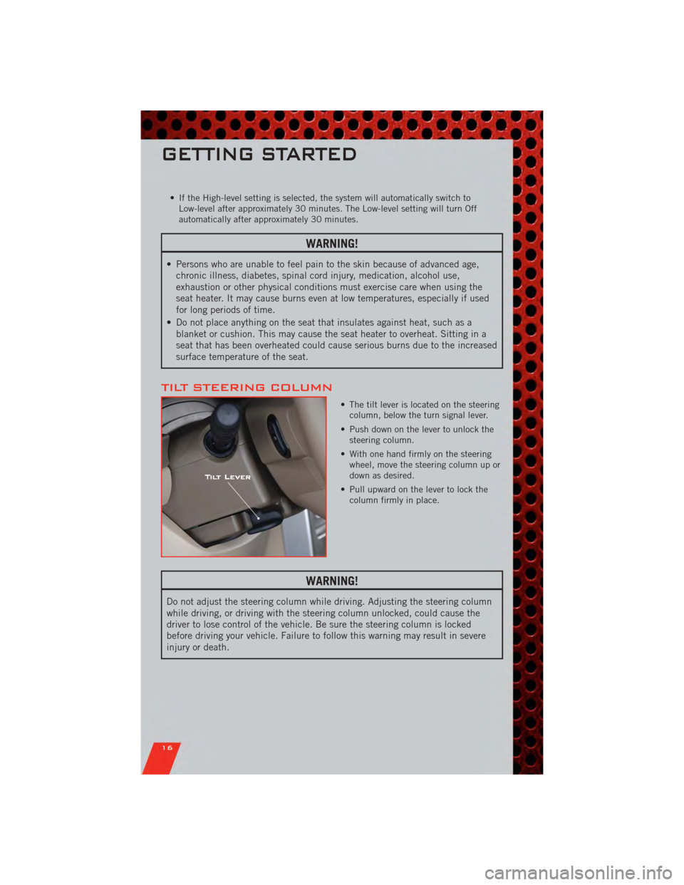
TILT STEERING COLUMN
• The tilt lever is located on the steeringcolumn, below the turn signal lever.
• Push down on the lever to unlock the steering column.
• With one hand firmly on the steering wheel, move the steering column up or
down as desired.
• Pull upward on the lever to lock the column firmly in place.
WARNING!
Do not adjust the steering column while driving. Adjusting the steering column
while driving, or driving with the steering column unlocked, could cause the
driver to lose control of the vehicle. Be sure the steering column is locked
before driving your vehicle. Failure to follow this warning may result in severe
injury or death.
GETTING STARTED
16
Page 33 of 80
• Touch one of the ADD PICTURES soft-keys, then select the type of media inserted.
• Use the PAGE soft-keys to page through a list of pictures and press the picture youwould like to import.
• Confirm your selection by touching the YES soft-key. The imported picture is now available in the MANAGE MY PICTURES screen.
• In order to display the imported picture in the radio screen, touch the desired picture soft-key.
• Select this picture by pressing the PICTURE VIEW soft-key. A check mark indicates the currently used picture.
Cleaning Your Touch-Screen Radio
• Do not spray any liquid or caustic chemicals directly on the screen. Use a cleanand dry micro fiber lens cleaning cloth in order to clean the touch-screen.
• If necessary, use a lint-free cloth dampened with a cleaning solution such as isopropyl alcohol or an isopropyl alcohol and water solution ratio of 50:50. Be sure
to follow the solvent manufacturer's precautions and directions.
USB Port
• The USB Port on the radio allows you to copy songs from a connected USB drive orsupported media device onto your Media Center hard drive.
• The USB port located in the glove box also offers the ability to play songs from connected USB drives, or supported media devices. Supported devices may be
controlled through the vehicles steering wheel or radio controls and may be
charged through the USB port.
Navigation – Media Center 430N (Sales Code RHB) Only
• For software updates, visit http://www.garmin.com/chrysler website, or contact yourauthorized dealer for the latest available software.
• The Navigation system receives GPS signals from satellites to display the position of your vehicle. You may experience interruptions or delays in receiving navigation
information in garages, tunnels, large cities, or other situations where the vehicle
does not have a direct line of sight to the sky.
• Voice Command is not available for navigation commands on this radio (although Voice Command functions for all other radio functions).
Map • Touch the NAV soft-key in the upper-right corner of your radio screen, to access the Navigation system.
• Touch the View Mapsoft-key to display a map of your current position.
Finding a Point of Interest • Touch the NAV soft-key in the upper-right corner of your radio screen to access the Navigation system.
• Touch the Where To?soft-key to program a destination.
• Next touch one of the subcategories to search for your destination. Address, Points of Interest, Recently Found, Favorites and Intersection are a few of the options.
ELECTRONICS
31
Page 35 of 80
•Movie Listings
• Check which movies (includes start times, ratings, run lengths and summaries)
are playing at theaters near your current location.
• Sports Scores
• View scores and upcoming events for all major sports.
• Your favorite location, theater and sports teams can be stored for quick access.
• Refer to your Media Center 730N (RHR) User's Manual or Media Center 430/430N (RBZ/RHB) User's Manual for more details.
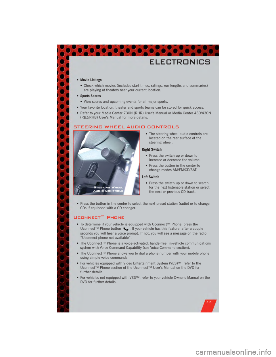
STEERING WHEEL AUDIO CONTROLS
• The steering wheel audio controls arelocated on the rear surface of the
steering wheel.
Right Switch
• Press the switch up or down toincrease or decrease the volume.
• Press the button in the center to change modes AM/FM/CD/SAT.
Left Switch
• Press the switch up or down to searchfor the next listenable station or select
the next or previous CD track.
• Press the button in the center to select the next preset station (radio) or to change CDs if equipped with a CD changer.
Uconnect™ Phone
• To determine if your vehicle is equipped with Uconnect™ Phone, press theUconnect™ Phone button. If your vehicle has this feature, after a couple
seconds you will hear a voice prompt. If not, you will see a message on the radio
“Uconnect phone not available”.
• The Uconnect™ Phone is a voice-activated, hands-free, in-vehicle communications system with Voice Command Capability (see Voice Command section).
• The Uconnect™ Phone allows you to dial a phone number with your mobile phone using simple voice commands.
• For vehicles equipped with Video Entertainment System (VES)™, refer to the Uconnect™ Phone section of the Uconnect™ User's Manual on the DVD for
further details.
• For vehicles not equipped with VES™, refer to your vehicle Owner's Manual on the DVD for further details.
ELECTRONICS
33
Page 37 of 80
Transfer Ongoing Call Between Handset And Vehicle
• During a call, press the Voice Command button.
• (After the BEEP), say “transfer call”.
Changing The Volume
• Start a dialogue by pressing the Phone button, then adjust the volume during
a normal call.
• Use the radio ON/OFF VOLUME rotary knob to adjust the volume to a comfortable level while the Uconnect™ system is speaking. Please note the volume setting for
Uconnect™ is different than the audio system.
NOTE: To access the tutorial, press the Uconnect™ hard-key. After the BEEP, say
“tutorial”. Press any hard-key/button or touch the display (Touch-Screen radio) to
cancel the tutorial.
WARNING!
• Any voice commanded system should be used only in safe driving conditions following local laws and phone use. All attention should be kept on the
roadway ahead. Failure to do so may result in a collision causing you and
others to be severely injured or killed.
• In an emergency, to use Uconnect™ Phone, your mobile phone must be: • turned on,
• paired to Uconnect™ Phone,
• and have network coverage.
Uconnect™ VOICE COMMAND
• The Uconnect™ Voice Command system allows you to control your AM, FM radio,satellite radio, disc player, Uconnect™ Phone, a memo recorder, and supported
portable media devices. The Voice Command system also provides limited
capability to select and play music by artist, song, album, music, genre, or playlist
from your compatible iPod
®device (this capability is available for Media Center
430/430N when connected to the USB port).
• When you press the Voice Command button
located on the radio faceplate
or steering wheel, you will hear a beep. The beep is your signal to give a command.
If you do not say a command within a few seconds, the system will present you
with a list of options. If you ever wish to interrupt the system while it lists options,
press the Voice Command button
, listen for the BEEP, and say your
command.
Voice Command for Text Messaging
• If equipped with Uconnect™ Voice Command, your Media Center 430N radio may be able to play incoming SMS messages through the vehicle sound system.
• It also allows you to respond by selecting from various pre-defined phrases.
ELECTRONICS
35
Page 46 of 80
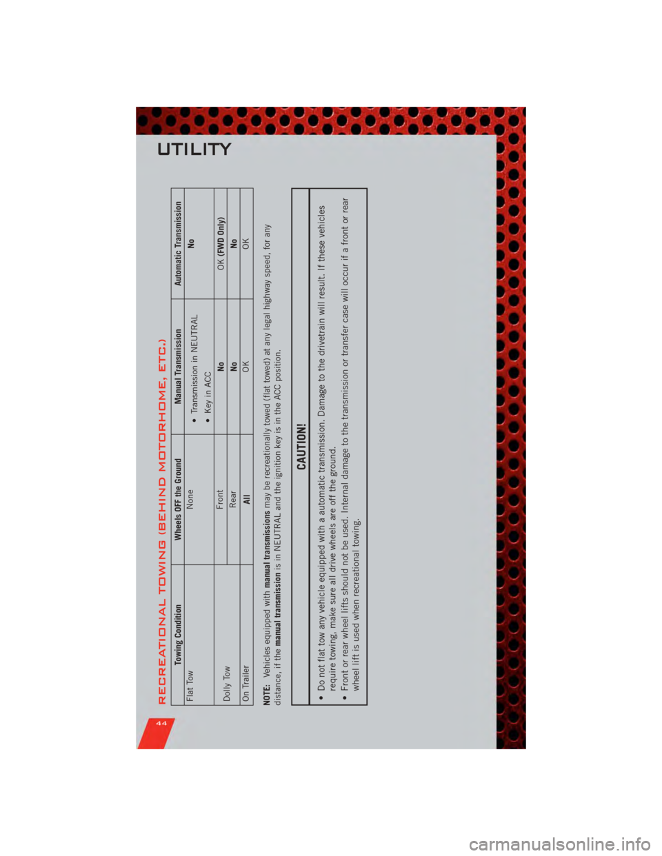
RECREATIONAL TOWING (BEHIND MOTORHOME, ETC.)
Towing ConditionWheels OFF the Ground Manual TransmissionAutomatic Transmission
Flat Tow None
• Transmission in NEUTRAL
• Key in ACC No
Dolly Tow Front
NoOK(FWD Only)
Rear NoNo
On Trailer AllOK
OK
NOTE: Vehicles equipped with manual transmissionsmay be recreationally towed (flat towed) at any legal highway speed, for any
distance, if the manual transmission is in NEUTRAL and the ignition key is in the ACC position.
CAUTION!
• Do not flat tow any vehicle equipped with a automatic transmission. Damage to the drivetrain will result. If these vehicles
require towing, make sure all drive wheels are off the ground.
• Front or rear wheel lifts should not be used. Internal damage to the transmission or transfer case will occur if a front or rear wheel lift is used when recreational towing.
UTILITY
44
Page 48 of 80
• Please note that the TPMS is not a substitute for proper tire maintenance, and it isthe driver’s responsibility to maintain correct tire pressure, even if under-inflation
has not reached the level to trigger illumination of the TPMS low tire pressure
telltale.
• Your vehicle has also been equipped with a TPMS malfunction indicator to indicate when the system is not operating properly. The TPMS malfunction indicator is
combined with the low tire pressure telltale. When the system detects a
malfunction, the telltale will flash for approximately one minute and then remain
continuously illuminated. This sequence will continue each time the vehicle is
restarted as long as the malfunction exists.
• When the malfunction indicator is illuminated, the system may not be able to detect or signal low tire pressure as intended. TPMS malfunctions may occur for a
variety of reasons, including the installation of replacement or alternate tires or
wheels on the vehicle that prevent the TPMS from functioning properly. Always
check the TPMS malfunction telltale after replacing one or more tires or wheels on
your vehicle, to ensure that the replacement or alternate tires and wheels allow the
TPMS to continue to function properly.
CAUTION!
The TPMS has been optimized for the original equipment tires and wheels.
TPMS pressures and warning have been established for the tire size equipped
on your vehicle. Undesirable system operation or sensor damage may result
when using replacement equipment that is not of the same size, type, and/or
style. Aftermarket wheels can cause sensor damage. Do not use tire sealant
from a can, or balance beads if your vehicle is equipped with a TPMS, as
damage to the sensors may result.
- Engine Temperature Warning Light
• This light warns of an overheated engine condition.
• If the light turns on and a warning chime sounds while driving, safely pull over andstop the vehicle. If the A/C system is on, turn it off. Also, shift the transmission
into NEUTRAL and idle the vehicle. If the temperature reading does not return to
normal, turn the engine off immediately.
• We recommend that you do not operate the vehicle or engine damage will occur. Have the vehicle serviced immediately.
WARNING!
A hot engine cooling system is dangerous. You or others could be badly burned
by steam or boiling coolant. You may want to call an authorized service center
for service if your vehicle overheats.
WHAT TO DO IN EMERGENCIES
46
Page 52 of 80
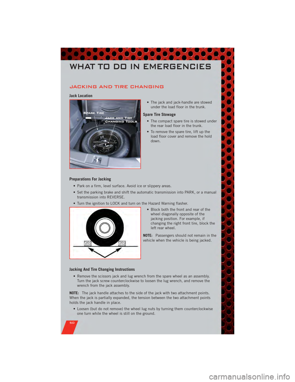
JACKING AND TIRE CHANGING
Jack Location
• The jack and jack-handle are stowedunder the load floor in the trunk.
Spare Tire Stowage
• The compact spare tire is stowed underthe rear load floor in the trunk.
• To remove the spare tire, lift up the load floor cover and remove the hold
down.
Preparations For Jacking
• Park on a firm, level surface. Avoid ice or slippery areas.
• Set the parking brake and shift the automatic transmission into PARK, or a manual
transmission into REVERSE.
• Turn the ignition to LOCK and turn on the Hazard Warning flasher. • Block both the front and rear of thewheel diagonally opposite of the
jacking position. For example, if
changing the right front tire, block the
left rear wheel.
NOTE: Passengers should not remain in the
vehicle when the vehicle is being jacked.
Jacking And Tire Changing Instructions
• Remove the scissors jack and lug wrench from the spare wheel as an assembly. Turn the jack screw counterclockwise to loosen the lug wrench, and remove the
wrench from the jack assembly.
NOTE: The jack handle attaches to the side of the jack with two attachment points.
When the jack is partially expanded, the tension between the two attachment points
holds the jack handle in place.
• Loosen (but do not remove) the wheel lug nuts by turning them counterclockwiseone turn while the wheel is still on the ground.
WHAT TO DO IN EMERGENCIES
50
Page 53 of 80
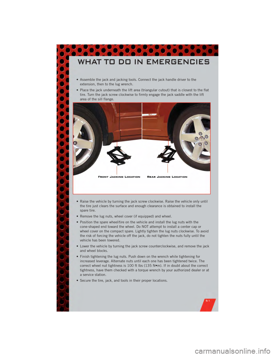
• Assemble the jack and jacking tools. Connect the jack handle driver to theextension, then to the lug wrench.
• Place the jack underneath the lift area (triangular cutout) that is closest to the flat tire. Turn the jack screw clockwise to firmly engage the jack saddle with the lift
area of the sill flange.
• Raise the vehicle by turning the jack screw clockwise. Raise the vehicle only until the tire just clears the surface and enough clearance is obtained to install the
spare tire.
• Remove the lug nuts, wheel cover (if equipped) and wheel.
• Position the spare wheel/tire on the vehicle and install the lug nuts with the cone-shaped end toward the wheel. Do NOT attempt to install a center cap or
wheel cover on the compact spare. Lightly tighten the lug nuts clockwise. To avoid
the risk of forcing the vehicle off the jack, do not tighten the nuts fully until the
vehicle has been lowered.
• Lower the vehicle by turning the jack screw counterclockwise, and remove the jack and wheel blocks.
• Finish tightening the lug nuts. Push down on the wrench while tightening for increased leverage. Alternate nuts until each one has been tightened twice. The
correct wheel nut tightness is 100 ft lbs (135 N•m). If in doubt about the correct
tightness, have them checked with a torque wrench by your authorized dealer or at
a service station.
• Secure the tire, jack, and tools in their proper locations.
WHAT TO DO IN EMERGENCIES
51