maintenance DODGE CALIBER SRT 2008 1.G Owners Manual
[x] Cancel search | Manufacturer: DODGE, Model Year: 2008, Model line: CALIBER SRT, Model: DODGE CALIBER SRT 2008 1.GPages: 373, PDF Size: 3 MB
Page 2 of 373
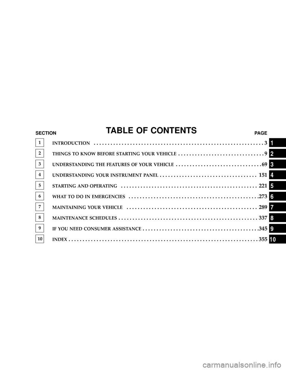
TABLE OF CONTENTSSECTIONPAGE
1INTRODUCTION.............................................................3
2THINGS TO KNOW BEFORE STARTING YOUR VEHICLE...............................9
3UNDERSTANDING THE FEATURES OF YOUR VEHICLE...............................69
4UNDERSTANDING YOUR INSTRUMENT PANEL................................... 151
5STARTING AND OPERATING................................................. 221
6WHAT TO DO IN EMERGENCIES...............................................273
7MAINTAINING YOUR VEHICLE............................................... 289
8MAINTENANCE SCHEDULES.................................................. 337
9IF YOU NEED CONSUMER ASSISTANCE..........................................345
10INDEX....................................................................355
1
2
3
4
5
6
7
8
9
10
Page 5 of 373
INTRODUCTION
This Owner's Manual has been prepared with the assis-
tance of service and engineering specialists to acquaint
you with the operation and maintenance of your vehicle.
It is supplemented by a Warranty Information Booklet
and various customer-oriented documents. You are
urged to read these publications carefully. Following the
instructions and recommendations in this manual will
help assure safe and enjoyable operation of your vehicle.
NOTE: After you read the manual, it should be stored
in the vehicle for convenient reference and remain with
the vehicle when sold, so that the new owner will be
aware of all safety warnings.
When it comes to service, remember that your authorized
dealer knows your vehicle best, has the factory-trained
technicians and genuine Mopartparts, and is interested
in your satisfaction.
HOW TO USE THIS MANUAL
Consult the table of contents to determine which section
contains the information you desire.
The detailed index, at the rear of this manual, contains a
complete listing of all subjects.
Consult the following table for a description of the
symbols that may be used on your vehicle or throughout
this owner's manual:
4 INTRODUCTION
Page 73 of 373
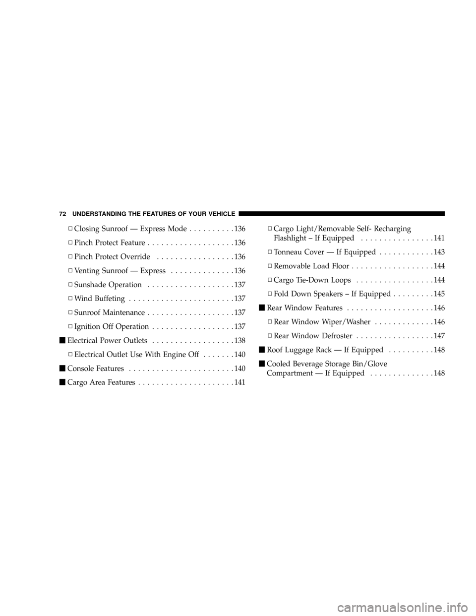
NClosing Sunroof Ð Express Mode..........136
NPinch Protect Feature...................136
NPinch Protect Override.................136
NVenting Sunroof Ð Express..............136
NSunshade Operation...................137
NWind Buffeting.......................137
NSunroof Maintenance...................137
NIgnition Off Operation..................137
mElectrical Power Outlets..................138
NElectrical Outlet Use With Engine Off.......140
mConsole Features.......................140
mCargo Area Features.....................141NCargo Light/Removable Self- Recharging
Flashlight ± If Equipped................141
NTonneau Cover Ð If Equipped............143
NRemovable Load Floor..................144
NCargo Tie-Down Loops.................144
NFold Down Speakers ± If Equipped.........145
mRear Window Features...................146
NRear Window Wiper/Washer.............146
NRear Window Defroster.................147
mRoof Luggage Rack Ð If Equipped..........148
mCooled Beverage Storage Bin/Glove
Compartment Ð If Equipped..............148
72 UNDERSTANDING THE FEATURES OF YOUR VEHICLE
Page 138 of 373
Sunshade Operation
The sunshade can be opened manually. However, the
sunshade will open automatically as the sunroof opens.
NOTE:The sunshade cannot be closed if the sunroof is
open.
Wind Buffeting
Wind buffeting can be described as the perception of
pressure on the ears or a helicopter-type sound in the
ears. Your vehicle may exhibit wind buffeting with the
windows down, or the sunroof (if equipped) in certain
open or partially open positions. This is a normal occur-
rence and can be minimized. If the buffeting occurs with
the rear windows open, open the front and rear windows
together to minimize the buffeting. If the buffeting occurs
with the sunroof open, adjust the sunroof opening to
minimize the buffeting or open any window.
Sunroof Maintenance
Use only a non-abrasive cleaner and a soft cloth to clean
the glass panel.
Ignition Off Operation
The sunroof will also operate up to 45 seconds after the
ignition has been turned off. The sunroof operation will
be canceled if either of the front doors are opened during
the accessory delay time or set accessory delay time.
UNDERSTANDING THE FEATURES OF YOUR VEHICLE 137
3
Page 155 of 373
NPTY Button9Seek9.....................208
NSatellite Antenna......................208
NReception Quality.....................209
mRemote Sound System Controls Ð If Equipped . . 209
NRadio Operation......................210
NCD Player..........................210mCD/DVD Disc Maintenance...............211
mRadio Operation And Cellular Phones........211
mTurbo Boost Gauge.....................212
mClimate Controls.......................213
NClimate Controls......................213
NAir Filtration System ± If Equipped........217
NOperating Tips.......................218
154 UNDERSTANDING YOUR INSTRUMENT PANEL
Page 161 of 373
EVIC display. For additional information, refer to ªElec-
tronic Vehicle Information Center Ð If Equippedº in
Section 3.
Change Oil Message
Your vehicle is equipped with an engine oil change
indicator system. The ªChange Oilº message will flash in
the instrument cluster odometer for approximately 12
seconds after a single chime has sounded to indicate the
next scheduled oil change interval. The engine oil change
indicator system is duty cycle based, which means the
engine oil change interval may fluctuate dependent upon
your personal driving style.
Unless reset, this message will continue to display each
time you turn the ignition switch to the ON/RUN
position. To turn off the message temporarily, press and
release the Trip Odometer button on the instrumentcluster. To reset the oil change indicator system (after
performing the scheduled maintenance) refer to the fol-
lowing procedure.
1. Turn the ignition switch to the ON position(Do not
start the engine).
2. Fully depress the accelerator pedal slowly three
times within 10 seconds.
3. Turn the ignition switch to the OFF/LOCK position.
NOTE:If the indicator message illuminates when you
start the vehicle, the oil change indicator system did not
reset. If necessary repeat this procedure.
14. Cruise Indicator Ð If Equipped
This indicator shows that the Speed Control
System is ON.
160 UNDERSTANDING YOUR INSTRUMENT PANEL
Page 164 of 373
22. Tire Pressure Monitor Light Ð If Equipped
Each tire, including the spare (if provided),
should be checked monthly when cold and
inflated to the inflation pressure recommended
by the vehicle manufacturer on the vehicle
placard or tire inflation pressure label. (If your vehicle
has tires of a different size than the size indicated on the
vehicle placard or tire inflation pressure label, you should
determine the proper tire inflation pressure for those
tires.)
As an added safety feature, your vehicle has been
equipped with a tire pressure monitoring system (TPMS)
that illuminates a low tire pressure telltale when one or
more of your tires are significantly under-inflated. Ac-
cordingly, when the low tire pressure telltale illuminates,
you should stop and check your tires as soon as possible,
and inflate them to the proper pressure. Driving on asignificantly under-inflated tire causes the tire to over-
heat and can lead to tire failure. Under-inflation also
reduces fuel efficiency and tire tread life, and may affect
the vehicle's handling and stopping ability.
Please note that the TPMS is not a substitute for proper
tire maintenance, and it is the driver 's responsibility to
maintain correct tire pressure, even if under-inflation has
not reached the level to trigger illumination of the TPMS
low tire pressure telltale.
The Tire Pressure Monitoring Telltale Lamp will illumi-
nate in the instrument cluster, and an audible chime will
be activated when one or more tire pressures is low. The
Tire Pressure Monitoring Telltale Lamp will flash on and
off for 60 seconds when a system fault is detected. The
flash cycle will repeat every ten minutes or until the fault
condition is removed and reset.
UNDERSTANDING YOUR INSTRUMENT PANEL 163
4
Page 177 of 373
indicator system is duty cycle based, which means the
engine oil change interval may fluctuate dependent upon
your personal driving style.
Unless reset, this message will continue to display each
time you turn the ignition switch to the ON/RUN
position. To turn off the message temporarily, press and
release the Menu button. To reset the oil change indicator
system (after performing the scheduled maintenance)
refer to the following procedure.
1. Turn the ignition switch to the ON position(Do not
start the engine).
2. Fully depress the accelerator pedal slowly three times
within 10 seconds.
3. Turn the ignition switch to the OFF/LOCK position.
NOTE:If the indicator message illuminates when you
start the vehicle, the oil change indicator system did not
reset. If necessary repeat this procedure.Setting The Compass Variance And Compass
Calibration
Compass Variance
Compass Variance is the difference between magnetic
North and Geographic North. In some areas of the
country, the difference between magnetic and geographic
North is great enough to cause the compass to give false
readings. In order to ensure compass accuracy, the com-
pass variance should be set to the zone number on the
compass variance map that corresponds to the current
location of the vehicle.
NOTE:Magnetic materials should be kept away from
the Instrument Panel. This is where the compass sensor is
located.
176 UNDERSTANDING YOUR INSTRUMENT PANEL
Page 212 of 373
CD/DVD DISC MAINTENANCE
To keep the CD/DVD discs in good condition, take the
following precautions:
1. Handle the disc by its edge; avoid touching the
surface.
2. If the disc is stained, clean the surface with a soft cloth,
wiping from center to edge.
3. Do not apply paper, paper CD labels, or tape to the
disc; avoid scratching the disc.
4. Do not use solvents such as benzine, thinner, cleaners,
or antistatic sprays.
5. Store the disc in its case after playing.
6. Do not expose the disc to direct sunlight.7. Do not store the disc where temperatures may become
too high.
8. Do not play discs that are small in size or have
irregular shapes.
RADIO OPERATION AND CELLULAR PHONES
Under certain conditions, the cellular phone being ON in
your vehicle can cause erratic or noisy performance from
your radio. This condition may be lessened or eliminated
by relocating the cellular phone antenna. This condition
is not harmful to the radio. If your radio performance
does not satisfactorily ªclearº by the repositioning of the
antenna, it is recommended that the radio volume be
turned down or off during cellular phone operation.
UNDERSTANDING YOUR INSTRUMENT PANEL 211
4
Page 218 of 373
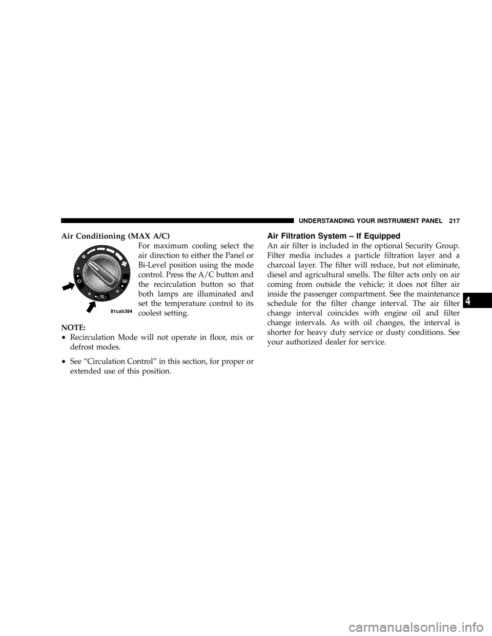
Air Conditioning (MAX A/C)
For maximum cooling select the
air direction to either the Panel or
Bi-Level position using the mode
control. Press the A/C button and
the recirculation button so that
both lamps are illuminated and
set the temperature control to its
coolest setting.
NOTE:
²Recirculation Mode will not operate in floor, mix or
defrost modes.
²See ªCirculation Controlº in this section, for proper or
extended use of this position.
Air Filtration System ± If Equipped
An air filter is included in the optional Security Group.
Filter media includes a particle filtration layer and a
charcoal layer. The filter will reduce, but not eliminate,
diesel and agricultural smells. The filter acts only on air
coming from outside the vehicle; it does not filter air
inside the passenger compartment. See the maintenance
schedule for the filter change interval. The air filter
change interval coincides with engine oil and filter
change intervals. As with oil changes, the interval is
shorter for heavy duty service or dusty conditions. See
your authorized dealer for service.
UNDERSTANDING YOUR INSTRUMENT PANEL 217
4