Steering lock DODGE CARAVAN 2004 4.G Owners Manual
[x] Cancel search | Manufacturer: DODGE, Model Year: 2004, Model line: CARAVAN, Model: DODGE CARAVAN 2004 4.GPages: 397, PDF Size: 6.83 MB
Page 104 of 397

a maximum of 20 seconds or until the lever is released. If
another washer cycle is desired the end of the lever must
be pressed again to get another 20 second washer cycle. If
the lever is depressed while in the delay range, the
wipers will operate for several seconds after the lever is
released, and then resume the intermittent interval pre-
viously selected.
If the end of the lever is depressed while in the OFF
position, the wipers will operate for approximately two
wipe cycles, then turn OFF.
WARNING!
Sudden loss of visibility through the windshield
could lead to an accident. You might not see other
vehicles or other obstacles. To avoid sudden icing of
the windshield during freezing weather, warm the
windshield with defroster before and during wind-
shield washer use.
Intermittent Wiper System
Use the intermittent wipers when weather conditions
make a single wiping cycle, with a variable pause be-
tween cycles, desirable.
Rotate the end of the lever to the first detent position,
then turn the end of the lever to select the desired delay
interval. The delay can be regulated from a maximum of
about 20 seconds between cycles, to a cycle every 2
seconds. The time delay will be doubled if the vehicle
speed is less than 10 mph (16 km/h).
TILT STEERING COLUMN Ð IF EQUIPPED
To tilt the column, pull the small lever, located behind the
turn signal control, toward you and move the wheel up
or down, as desired. Release the lever to lock the wheel
firmly in place.
104 UNDERSTANDING THE FEATURES OF YOUR VEHICLE
Page 105 of 397
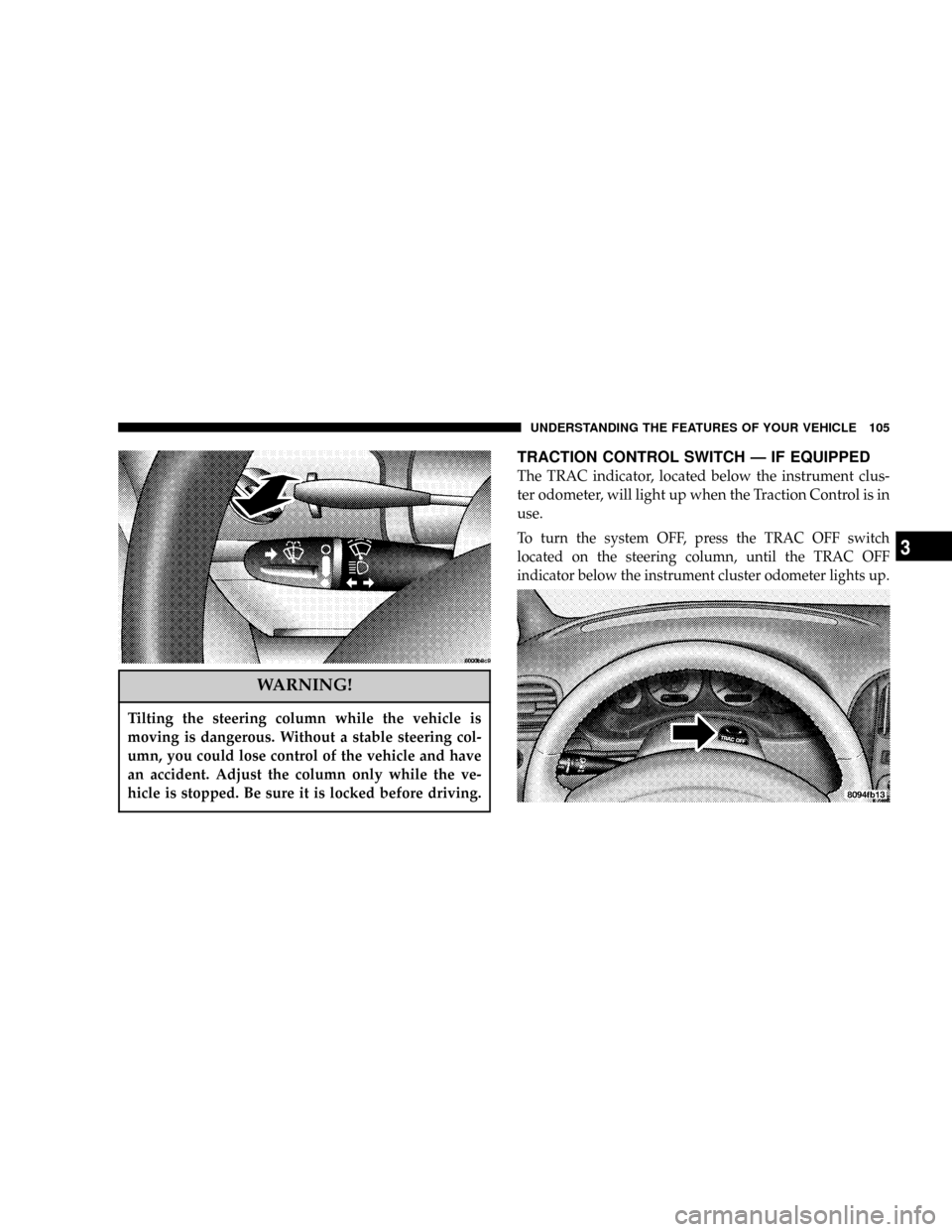
WARNING!
Tilting the steering column while the vehicle is
moving is dangerous. Without a stable steering col-
umn, you could lose control of the vehicle and have
an accident. Adjust the column only while the ve-
hicle is stopped. Be sure it is locked before driving.
TRACTION CONTROL SWITCH Ð IF EQUIPPED
The TRAC indicator, located below the instrument clus-
ter odometer, will light up when the Traction Control is in
use.
To turn the system OFF, press the TRAC OFF switch
located on the steering column, until the TRAC OFF
indicator below the instrument cluster odometer lights up.
UNDERSTANDING THE FEATURES OF YOUR VEHICLE 105
3
Page 107 of 397

²The pedalscannotbe adjusted when the vehicle is in R
(Reverse) or when the Speed Control System is ON.
The following messages will be displayed on vehicles
equipped with the Electronic Vehicle Information Sys-
tem (EVIC) if the pedals are attempted to be adjusted
when the system is locked out (ªAdjustable Pedal
Disabled Ð Cruise Control Engagedº or ªAdjustable
Pedal Disabled Ð Vehicle In Reverseº).
CAUTION!
Do not place any article under the adjustable pedals
or impede its ability to move as it may cause damage
to the pedal controls. Pedal travel may become
limited if movement is stopped by an obstruction in
the adjustable pedal's path.
ELECTRONIC SPEED CONTROL Ð IF EQUIPPED
When engaged, this device takes over the accelerator
operation at speeds greater than 30 mph (50 km/h). The
speed control switches are located on the steering wheel.
UNDERSTANDING THE FEATURES OF YOUR VEHICLE 107
3
Page 159 of 397

INFORMATION CENTER Ð IF EQUIPPED
Turn Signal Indicators
The arrow will flash with the exterior turn signal
when the turn signal lever is operated.
If the vehicle electronics sense that the vehicle has
traveled about one mile with the turn signals on, a chimewill sound to alert you to turn the signals off. If either
indicator flashes at a rapid rate, check for a defective
outside light bulb.
High Beam Light
This light shows that the headlights are on high
beam. Pull the turn signal lever towards the
steering wheel to switch the headlights from high or low
beam.
ELECTRONIC DIGITAL CLOCK
The clock and radio each use the display panel built into
the radio. A digital readout shows the time in hours and
minutes whenever the ignition switch is in the ON or
ACC position and the time button is pressed.
When the ignition switch is in the OFF position, or when
the radio frequency is being displayed, time keeping is
accurately maintained.
UNDERSTANDING YOUR INSTRUMENT PANEL 159
4
Page 195 of 397

NOTE:Follow the manufactures instructions for the
correct colors when connecting the RCA cables.
Operating Instructions Ð Video
Games/Camcorders
A video game unit or camcorder can be connected to the
rear audio/video system. Connect the cables to the RCA
jacks located on the front of the CD/DVD changer.
NOTE:To operate a video game unit a DC to AC
adapter may be required, plug the adapter into any
power outlet.
Follow the manufactures instructions for the correct
colors when connecting the RCA cables.
NOTE:MP3 player's, video game systems, camcorders
connected to the RCA jacks and CD's or DVD's inserted
into the CD/DVD changer can be heard through the
headphones.
REMOTE SOUND SYSTEM CONTROLS Ð IF
EQUIPPED
The remote sound system controls are located on the rear
surface of the steering wheel at the 3 and 9 O'clock
positions.
The right hand rocker switch has a push button in the
center and controls the volume and mode of the sound
UNDERSTANDING YOUR INSTRUMENT PANEL 195
4
Page 223 of 397

STARTING AND OPERATING
CONTENTS
mStarting Procedures.....................226
N2.4L Engine.........................226
N3.3L And 3.8L Engine..................228
mEngine Block Heater Ð If Equipped.........230
mAutomatic Transmission..................231
NBrake/Transmission Interlock System.......232
NAutomatic Transmission Ignition Interlock
System.............................232
NFour Speed Automatic Transmission........232mAll Wheel Drive Ð If Equipped............235
mParking Brake.........................235
mBrake System..........................237
NAnti-Lock Brake System Ð If Equipped.....237
mPower Steering........................240
mTraction Control Ð If Equipped............241
mTire Safety Information...................242
NTire Markings........................242
NTire Identification Number (TIN)..........246
5
Page 239 of 397

²and a slight drop or fall away of the brake pedal at the
end of the stop.
These are all normal characteristics of ABS.
WARNING!
The Anti-Lock Brake System contains sophisticated
electronic equipment that may be susceptible to
interference caused by improperly installed or high
output radio transmitting equipment. This interfer-
ence can cause possible loss of anti-lock braking
capability. Installation of such equipment should be
performed by qualified professionals.
WARNING!
²Anti-lock system (ABS) cannot prevent the natu-
ral laws of physics from acting on the vehicle, nor
can it increase braking or steering efficiency be-
yond that afforded by the condition of the vehicle
brakes and tires or the traction afforded.
²The ABS cannot prevent accidents, including
those resulting from excessive speed in turns,
following another vehicle too closely, or hydro-
planing. Only a safe, attentive, and skillful driver
can prevent accidents.
²The capabilities of an ABS equipped vehicle must
never be exploited in a reckless or dangerous
manner which could jeopardize the user's safety
or the safety of others.
STARTING AND OPERATING 239
5
Page 292 of 397

km/h). Exceeding these towing limits may cause a trans-
mission geartrain failure. If the transmission is not op-
erative, or if the vehicle is to be towed more than 100
miles (160 km), the vehicle must be towed with the front
wheels off the ground.
All Wheel Drive
Your vehicle may be towed under the following condi-
tions: The gear selector must be in NEUTRAL, the
distance to be traveled must not exceed 100 miles (160
km), the towing speed must not exceed 44 mph (72
km/h), and both front and rear wheels must be on the
ground. If your vehicle must be towed farther or at a
higher rate of speed, it must be transported on a flat bed
truck.
All Transmissions
CAUTION!
²Do not attempt to tow this vehicle from the front
with sling type towing equipment. Damage to the
front fascia will result.
²Always use wheel lift equipment when towing
from the front. The only other approved method
of towing is with a flat bed truck.
²Do not tow the vehicle from the rear. Damage to
the rear sheet metal, liftgate and fascia will occur.
²Do not push or tow this vehicle with another
vehicle as damage to the bumper fascia and trans-
mission may result.
²If the vehicle being towed requires steering, the
ignition switch must be in the OFF position, not
in the LOCK or ACCESSORY positions.
292 WHAT TO DO IN EMERGENCIES
Page 315 of 397

Steering Linkage
The tie rod end ball joints are permanently lubricated and
do not require periodic maintenance.
Drive Shaft Universal Joints
Your vehicle has constant velocity universal joints. Peri-
odic lubrication of these joints is not required. However,
the joint boots should be inspected for external leakage or
damage when other maintenance is performed. If leakage
or damage is evident, the universal joint boot and grease
should be replaced immediately.
Continued operation could result in failure of the univer-
sal joint due to water and dirt contamination of the
grease. This would require complete replacement of the
joint assembly.
Body Lubrication
Locks and all body pivot points, including such items as
seat tracks, doors, liftgate, sliding doors and hood hinges,
should be lubricated periodically to assure quiet, easy
operation and to protect against rust and wear. Prior to
the application of any lubricant, the parts concerned
should be wiped clean to remove dust and grit; after
lubricating excess oil and grease should be removed.
Particular attention should also be given to hood latching
components to insure proper function. When performing
other underhood services, the hood latch, release mecha-
nism and safety catch should be cleaned and lubricated.
The external lock cylinders should be lubricated twice a
year, preferably in the fall and spring. Apply a small
amount of a high quality lubricant such as MopartLock
Cylinder Lubricant directly into the lock cylinder.
MAINTAINING YOUR VEHICLE 315
7
Page 386 of 397

Air Cleaner Filter...................... 308
Block Heater......................... 230
Break-In Recommendations................ 70
Checking Oil Level..................... 303
Compartment......................298,299
Coolant............................. 344
Cooling............................. 318
Exhaust Gas Caution..................36,269
Fails to Start.......................227,229
Fuel Requirements..................... 266
Oil ..............................303,344
Oil Change Interval.................... 305
Oil Selection.......................... 305
Oil Synthetic......................... 307
Overheating.......................... 281
Temperature Gauge..................... 154
Exhaust Gas Caution..............36,71,269,317
Exhaust System......................... 317
Exterior Folding Mirrors................... 78Filters
Air Cleaner.......................... 308
Air Conditioning....................219,313
Automatic Transaxle.................... 328
Engine Fuel.......................... 309
Engine Oil........................307,344
Engine Oil Disposal.................... 307
Flashers
Hazard Warning....................... 280
Turn Signal..................158,159,340,342
Fluid Capacities......................... 343
Fluid Leaks............................. 72
Fluid Level Checks
Automatic Transaxle.................... 327
Brake............................... 345
Power Steering.....................314,345
Fog Light Service........................ 341
Fog Lights..........................102,341
Freeing A Stuck Vehicle................... 291
386 INDEX